Terminal block
The back of the central control
Not allowed Not allowed
Allowed
Insulation covering
Allowed Not allowed
Power supply wire
Signal wire
Note: Before connecting an external
timer or emergency stop input,
be sure to connect the wiring at
the worksite first.
④
③④
③
②
①
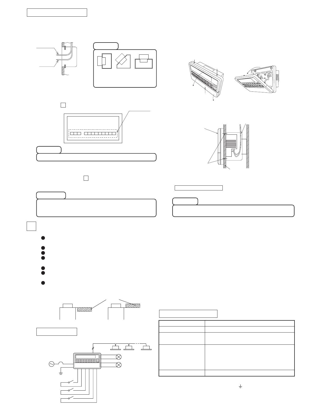
Operation output
Error output
Emergency stop input
AC100V-240V
50/60Hz
Demand input
External timer input
Super Link signal wire
Grounding work
Local
switch
L1, L2
Central control
④Pan-head screws
Electrical box
Internal wall or front side of the control board front
Note 1: When this central control is used, use a shielded wire for the Super Link signal wire.
Ground both ends of the shielded wire.
(Connect the ground for the central control to the section in "System Wiring".
Note 2: If the indoor and outdoor units connected to the network are all compatible units with
New Super Link, a total wire length of 1500m per line is possible (maximum distance:
1000m). However, be sure to use a 0.75mm
2
wire diameter if the total wire length
exceeds 1000m. For further information, please contact your sales representative or
dealer.
Refer to the figure below for the terminal orientation.
4Electrical Wiring
Wiring Outline
Wiring Specifications
Power supply wire
Local switch
Super Link signal wire
(Note 1, Note 2)
Operation output, error
output, demand input,
emergency stop input,
external timer input wire
Grounding wire
1.25
mm2
10A
0.75mm
2
- 1.25mm
2
shielded wire (MVVS 2-core)
Max. 1000m per line (Max. distance: 1000m, Total wire length: 1000m)
0.75mm2 - 1.25mm2 CCV, CPEV (2-core)
Max. 200m
0.75mm2 - 6mm2
Installation Procedure
Caution
Caution
Check the supply voltage, and make the correct connection.
Caution
The case and power supply kit are an integrated unit. Please do
not separate them.
Please do not install facing
upward or at a slant.
(2) Open the top case by following the procedure below.
① Grasp the indentations on the right and left sides, and
pull forward to open the cover downward.
② Use a Phillips-head screwdriver to remove the screw. (Be
careful not to lose the screw.)
③ Open the top section in the direction ④ while gently
pressing the top section.
(1) In case of embedding in a wall, first, embed the power supply
wire, signal wire, and Electrical box.
Keep the power supply wire and signal wire separated to
prevent malfunctions.
(5)
Use a precision screwdriver to make the control selector settings.
(For details, see section Control Switch Selection.)
(4) Use the supplied ④ pan-head screws to secure the central
control to the electrical box or control board.
(6) Peel off the protective sheet on the screen of central control.
Important
Please peel off the protective sheet on the air conditioner screen
when transferring the central control to the customer.
Peel off before mounting the top case.
(3) Connect the power supply wire to the terminal.
(See section Electrical Wiring.)
4
5
Before connecting the wires, remove the cover of the terminal block.
After the work is completed, fix the cover of the terminal block as before.
The cover is used to prevent electric shock due to accidental contact.
(7) Insert the top case back into its original location in the bottom
case as before, and tighten the case mounting screws
( Installation procedure (2) ②).
This completes the installation procedure.
For safety reasons, please use the round crimping terminals with insulated sleeves for connecting all wires to the central control.
Please do the grounding work. Please do not connect earth line with gas pipes, water pipes, lightning rods and grounding line of
telephone.
Please do not turn on the power supply (local switch) until all of the work is completed.
Please wait at least two minutes after the indoor and outdoor units are turned on before turning on the power supply.
Except for the central control in the figure, all of the components are obtained at the site (wires, switches, relays, power supply,
lamps, etc.).
Please be sure to build the breaker which is easily accessible with building equipment's wiring.
Please be sure to use the supplied round crimping terminals when connecting wires to the power supply terminal block and
Super Link terminal block.
Please use demand input device, emergency stop input device and external timer input device comply with a relevant IEC Safety Standard.
Downloaded from www.Manualslib.com manuals search engine


