
DATASHEET
β
α
SOUND SYSTEM SPECIALIST
Istruzioni per l’uso • Instructions for use • Manuel d’utilisation • Gebrauchsanleitung • Gebruiksaanwijzing • Instrucciones de uso
DLC9000
Regolatore automatico di volume
Digital level controller
Régulateur automatique de niveau
Automatischer Equalizer
Automatische niveauregelaar
Regulador automático de nivel
Español
Les agradecemos que hayan elegido un producto PASO y deseamos recordarles que nuestra empresa trabaja con sistema de
calidad certifi cado. Todos nuestros productos son pues controlados en cada fase de la producción para garantizarles una plena
satisfacción en su adquisición. Para cualquier tipo de eventualidad la garantía cubrirá, durante el periodo de validez, eventuales
defectos de fabricación. Les aconsejamos que lean detenidamente y se ajusten a las siguientes instrucciones de uso, para utilizar
correctamente este producto y aprovechar al máximo sus prestaciones.
Nederlands
Wij danken u voor uw keuze van een PASO product en herinneren u eraan dat de productie van ons bedrijf volgens een certifi ceerd
kwaliteitssysteem plaatsvindt. Onze producten worden daarom in iedere productiefase controleerd zodat u zeker tevreden zult zijn
met uw aankoop. Eventuele fabrieksfoutjes zijn in de periode dat de garantie geldig is, gedekt. Voor een goed gebruik van dit product
en voor een volledige benutting van de prestaties hiervan, raden wij u aan onderstaande gebruiksvoorschriften met aandacht door
te lezen.
Deutsch
Wir danken Ihnen für die Wahl eines PASO-Produkts und möchten Sie daran erinnern, dass wir mit einem zertifi zerten anerkannten
Qualitätssicherungssystem arbeiten. D.h., alle unsere Produkte werden in jeder Fertigungsphase kontrolliert, um Ihre vollständige
Zufriedenheit zu gewährleisten. Während des Gültigkeitszeitraums deckt die Garantie auf jeden Fall eventuell vorliegende
Produktionsmängel ab. Wir empfehlen Ihnen, die hier vorliegende Bedienungsanweisung aufmerksam zu lesen, um das Leistungsangebot
des Produkts voll nutzen zu können und um Probleme beim Gebrauch zu vermeiden.
Français
Vous remerciant d’avoir accordé votre préférence à un produit PASO, nous tenons à vous rappeler que nous appliquons à notre production
un Système Qualité certifi é. Aussi, pour donner entière satisfaction à notre clientèle, tous nos produits sont contrôlés à chaque étape
de la production. Ils sont en outre garantis contre tout défaut de fabrication pendant toute la période de validité de la garantie. Nous
vous recommandons de lire attentivement les instructions d’installation et d’utilisation qui suivent; elles vous permettront d’obtenir le
maximum des prestations offertes par le produit et en outre d’éviter tout problème.
English
While thanking you for having chosen a PASO product, we would like to remind you that our company works according to a certifi ed
Quality System. This means that all our products are checked during every phase of manufacturing in order to ensure that you will
be fully satisfi ed with your purchase. In any case, the guarantee will cover any manufacturing fl aws during the guarantee period. We
recommend that you read the following instructions for use and follow them carefully in order to exploit in full the performance of
this product and use it correctly.
Italiano
Nel ringraziarVi per aver scelto un prodotto PASO, vogliamo ricordarVi che la nostra azienda opera con sistema di qualità certifi cato.
Tutti i nostri prodotti vengono pertanto controllati in ogni fase della produzione per garantirVi la piena soddisfazione del Vostro
acquisto. Per ogni evenienza la garanzia coprirà, nel periodo di validità, eventuali difetti di fabbricazione. Vi raccomandiamo di
leggere attentamente le seguenti istruzioni d’uso per sfruttare appieno le prestazioni offerte da questo prodotto e per evitare
eventuali problemi.

DATASHEET
α
2
WARRANTY
This product is warranted to be free from defects in raw materials and
assembly. The warranty period is governed by the applicable provisions of
law. Paso will repair the product covered by this warranty free of charge
if it is faulty, provided the defect has occurred during normal use. The
warranty does not cover products that are improperly used or installed,
mechanically damaged or damaged by liquids or the weather. If the product
is found to be faulty, it must be sent to Paso free of charges for shipment
and return. This warranty does not include any others, either explicit or
implicit, and does not cover consequential damage to property or personal
injury. For further information concerning the warranty contact your local
PASO distributor.
Important!
Before using the apparatus, make yourself aware of all characteristics by
reading carefully the instructions included in the printed manual or on the CD,
paying particular attention to the safety notes.
Should the user wish to avail himself of servicing under the warranty, he
must provide evidence of the purchase (invoice or receipt). The user shall
also indicate the date of purchase, model and serial number indicated on the
equipment. For this reason, you should complete the box below as a reminder
of the data required.
Tutti gli apparecchi PASO sono costruiti nel rispetto delle più severe normative
internazionali di sicurezza ed in ottemperanza ai requisiti della Comunità
Europea. Per un corretto ed effi cace uso dell’apparecchio è importante prendere
conoscenza di tutte le caratteristiche leggendo attentamente le presenti
istruzioni ed in particolare le note di sicurezza.
All PASO equipment is manufactured in accordance with the most stringent
international safety standards and in compliance with European Community
requisites. In order to use the equipment correctly and effectively, it is
important to be aware of all its characteristics by reading these instructions
and in particular the safety notes carefully.
GARANZIA
Questo prodotto è garantito esente da difetti nelle sue materie prime e
nel suo montaggio; il periodo di garanzia è regolamentato dalle norme
vigenti. La Paso riparerà gratuitamente il prodotto difettoso qui garantito se
il difetto risulterà essersi verifi cato durante l’uso normale; la garanzia non
si estende quindi a prodotti usati ed installati in modo errato, danneggiati
meccanicamente, danneggiati da liquidi o da agenti atmosferici. Il prodotto,
risultato difettoso, dovrà essere inviato alla Paso franco di spese di
spedizione e ritorno. Questa garanzia non ne comprende altre, esplicite
od implicite, e non comprende danni o incidenti conseguenti a persone o
cose. Contattare i distributori PASO della zona per maggiori informazioni
sulla garanzia.
Importante!
Prima di usare l’apparecchio, prendere conoscenza di tutte le caratteristiche
leggendo attentamente le istruzioni contenute nel manuale cartaceo o su
supporto cd, ponendo particolare attenzione alle note di sicurezza.
L’utente ha la responsabilità di produrre una prova d’acquisto (fattura o
ricevuta) se vuole servirsi dell’assistenza coperta da garanzia. Dovrà inoltre
fornire data di acquisto, modello e numero di serie riportati sull’apparecchio;
a questo scopo, compilare come promemoria dei dati richiesti lo spazio qui
sotto.
MODELLO / MODEL: .............................................................................................................................................................................................
NUMERO DI SERIE / SERIAL NUMBER: ..................................................................................................................................................................
DATA D’ACQUISTO / PURCHASE DATE: ..................................................................................................................................................................
Questo prodotto è conforme alle Direttive della Comunità
Europea sotto le quali lo stesso ricade. This product is in keeping with the relevant European
Community Directives.
INDICE DEI CONTENUTI
1. Descrizione generale ............................................................ 3
1.1 Introduzione ..................................................................... 3
1.2 Pannello frontale ............................................................... 3
1.3 Pannello posteriore ..........................................................3
2. Avvertenze generali ............................................................. 3
2.1 Installazione ..................................................................... 3
2.2 Note di sicurezza ............................................................... 4
2.3 Alimentazione e messa a terra ........................................... 4
2.4 Montaggio a rack .............................................................. 4
3. Connessioni .......................................................................... 5
3.1 Esempio d’installazione ...................................................... 5
3.2 Ingresso/uscita linea ......................................................... 5
3.3 Ingresso ‘SENS MIC.’ .........................................................5
3.4 Morsettiera multifunzione ..................................................6
3.5 Suggerimenti per una corretta installazione .........................7
4. Messa in funzione .................................................................7
4.1 Operazioni preliminari ............................................................... 7
4.2 Taratura dell’apparecchio .......................................................... 7
4.3 Descrizione del menu ............................................................... 8
Schema........................................................................................ 26
Caratteristiche tecniche ............................................................. 27
Lista delle parti di ricambio ....................................................... 28
PASO S.p.A declina ogni responsabilità per danni a cose e/o persone derivanti
dall’uso non corretto dell’apparecchio o da procedure non rispondenti a quanto
riportato sul presente libretto. Nel continuo intento di migliorare i propri
prodotti, la PASO S.p.A. si riserva il diritto di apportare modifi che ai disegni e
alle caratteristiche tecniche in qualsiasi momento e senza alcun preavviso.
PASO S.p.A will not accept any liability for damage to property and/or persons
arising out of incorrect use of the equipment or of procedures that do not comply
with the instructions provided in this booklet. PASO S.p.A. strive to improve their
products continuously, and therefore reserve the right to make changes to the
drawings and technical specifi cations at any time and without notice.
TABLE OF CONTENTS
1. General description .............................................................. 3
1.1 Introduction......................................................................3
1.2 Front panel .......................................................................3
1.3 Rear panel ........................................................................ 3
2. General warnings ................................................................. 3
2.1 Installation ....................................................................... 3
2.2 Safety notes ..................................................................... 4
2.3 Power supply and earthing................................................. 4
2.4 Rack mounting .................................................................. 4
3. Connections .......................................................................... 5
3.1 Example of an installation ..................................................5
3.2 Line input/output .............................................................. 5
3.3 ‘SENS MIC.’ input .............................................................. 5
3.4 Multi-purpose terminal strip ............................................... 6
3.5 Suggestions for correct installation ..................................... 7
4. Power-up .............................................................................. 7
4.1 Preliminary operations .............................................................. 7
4.2 Calibration of the equipment ..................................................... 7
4.3 Menu description...................................................................... 8
Chart ........................................................................................... 26
Technical specifi cations ............................................................. 27
List of spare parts ....................................................................... 28

DATASHEET
DLC9000
3
1. DESCRIZIONE GENERALE
1.1 Introduzione
Il DLC9000 adegua in modo automatico il livello d’ascolto di un
impianto di diffusione sonora, controllando il segnale di pilotaggio degli
amplifi catori, sulla base di una monitorizzazione continua del rumore di
fondo presente nella zona di ascolto. Il rumore, rilevato dal microfono di
SENSE posto nell’area soggetta a controllo, viene campionato ed elaborato
dall’apparecchio per fornire l’adeguata correzione in dipendenza anche dei
parametri impostati al momento dell’installazione; sul display retroilluminato
sono riportati, a livello indicativo, sia il livello di pressione acustica del rumore
che il tasso di correzione introdotto dall’apparecchio sul segnale di linea.
Come ausilio all’installatore nella messa a punto del sistema, l’apparecchio e’
in grado di memorizzare i valori minimo e massimo rilevati nell’ambiente.
Una seconda modalità di funzionamento è rappresentata dalla possibilità di
operare come attenuatore ‘giorno/notte’, i cui valori di attenuazione sono
impostabili da menu e la selezione tra i due livelli è attivabile attraverso la
chiusura di un contatto della morsettiera multifunzione.
Dotato di un software di navigazione di facile uso per le impostazioni e
la calibrazione del sistema, l’apparecchio è completato da un altoparlante
monitor per il riascolto di ciò che viene captato dal microfono di SENSE e
dal controllo remotizzabile di BY-PASS che interviene in modo automatico
nel caso di mancanza di alimentazione.
1.2 Pannello frontale
1) Display LCD retroilluminato.
2) Tasto richiamo menu.
3) Tasto scorrimento menu ().
4) Tasto scorrimento menu ().
5) Tasto by-pass.
6) Altoparlante monitor.
7) Interruttore di rete.
1.3 Pannello posteriore
8) Spina di rete con fusibile incorporato.
9) Morsettiera multifunzione estraibile.
10) Uscita di linea bilanciata.
11) Ingresso di linea bilanciato.
12) Ingresso bilanciato per microfoni MC101-P, M961-B.
1. GENERAL DESCRIPTION
1.1 Introduction
The DLC9000 automatically adapts the listening level of a sound-
broadcasting system by controlling the signal that drives the amplifi ers,
on the basis of continuous monitoring of the background noise present in
the listening area. The noise, which is detected by the SENSE microphone
positioned in the area to be controlled, is sampled and processed by the
equipment in order to provide the appropriate correction, depending
also on the parameters that were set at the time of installing it. Both the
level of acoustic pressure of the noise and the amount of correction that
is introduced into the line signal are shown, indicatively, on the backlit
display. As a help for the installer in setting up the system, the equipment
is capable of storing the minimum and maximum values sensed in the
room. A second operating mode consists of the possibility of functioning
as a ‘day/night’ attenuator, the attenuation values of which can be set from
a menu. Switching between the two levels can be activated by closing a
contact on the multi-purpose terminal strip.
The equipment has its own user-friendly navigation software for making
the settings and calibrating the system, and it comes complete with a
monitoring loudspeaker in order to play back what is being detected by the
SENSE microphone and by the BY-PASS remote control which is activated
automatically in the event of a power failure.
1.2 Front panel
1) LCD with backlighting.
2) Menu key.
3) Menu UP key ().
4) Menu DOWN key ().
5) By-pass key.
6) Monitoring loudspeaker.
7) Mains switch.
1.3 Rear panel
8) Mains plug with built-in fuse.
9) Pull-out multi-purpose terminal strip.
10) Balanced line output.
11) Balanced line input.
12) Balanced input for MC101-P and M961-B microphones.
2. AVVERTENZE GENERALI
2.1 Installazione
Tutti gli apparecchi PASO sono costruiti nel rispetto delle più severe
normative internazionali di sicurezza ed in ottemperanza ai requisiti
della Comunità Europea. Per un corretto ed effi cace uso del regolatore
è importante prendere conoscenza di tutte le caratteristiche leggendo
attentamente le presenti istruzioni ed in particolare le note di sicurezza.
Durante il funzionamento dell’apparecchio è necessario assicurare
un’adeguata ventilazione. Evitare di racchiudere il DLC9000 in un
mobile privo di aerazione o di tenerlo in prossimità di sorgenti di calore.
Assicurarsi che tutti gli ingressi e le uscite siano correttamente collegati
prima dell’accensione.
2. GENERAL WARNINGS
2.1 Installation
All PASO equipment is made in compliance with the most stringent
international safety standards and to comply with European Community
requisites. To use the controller correctly and effi ciently it is important to be
aware of all its specifi cations by reading carefully these instructions and, in
particular, the safety notes. While the equipment is working, it is necessary
to ensure that it is suffi ciently ventilated. Avoid closing the DLC9000 in an
unventilated cabinet or keeping it in the vicinity of sources of heat.
Before switching on the equipment, make sure that all the inputs and the
outputs are correctly connected.

DATASHEET
α
4
2.2 Note di sicurezza
La rimozione del coperchio dell’apparecchio presenta il rischio di scosse
elettriche. Ogni intervento all’interno dell’apparecchio deve essere eseguito
da personale specializzato. Prima di procedere alla sostituzione dei fusibili,
accertarsi di avere staccato il cavo di rete e l’eventuale alimentazione
secondaria. La sostituzione deve essere effettuata con fusibili dello stesso
tipo e valore. Non rimuovere mai il conduttore di terra dal cavo di rete.
Ad evitare il pericolo di scosse elettriche o guasti, non introdurre oggetti
specialmente se metallici, attraverso le aperture dell’apparecchio. Nel caso
di accidentale caduta di liquidi sull’apparecchio, staccare immediatamente
la spina di rete ed interpellare il centro di assistenza PASO più vicino.
IMPORTANTE!
La PASO declina ogni responsabilità per danni a cose e/o persone derivanti
dall’uso non corretto dell’apparecchio o da procedure non rispondenti a
quanto riportato sul presente libretto.
2.2 Safety notes
There is a risk of electric shock if the cover of the equipment is removed. Any
activities inside the equipment must be carried out by specialised personnel.
Before proceeding to replace the fuses make sure that the power-supply cable
has been disconnected as well as the secondary power supply, if any. If it is
necessary to replace the fuses, this must be done with the same type and
having the same rating. Never remove the earth wire from the mains cable.
In order to avoid the danger of electric shocks or failures, to not introduce
any objects and in particular not metal objects into the openings on the
equipment. If any liquid is accidentally spilt on the equipment, disconnect the
power plug immediately and contact the nearest PASO service centre.
IMPORTANT!
PASO will not accept any liability for damage to property or personal injury
arising out of incorrect use of the equipment or of procedures that do not
comply with the information provided in this booklet.
2.3 Alimentazione e messa a terra
L’apparecchio é predisposto per il funzionamento con tensione di rete a
230 V ± 10%, 50/60 Hz. Il fusibile di rete è accessibile dal pannello
posteriore dell’apparecchio (8). In alternativa, è previsto il funzionamento
con una tensione continua esterna di 24V applicabile ai relativi morsetti (9c).
In accordo con le normative di sicurezza, l’interruttore di accensione
(7) agisce solo sulla tensione di rete. L’apparecchio é corredato di cavo di
alimentazione con fi lo di messa a terra ed il relativo terminale sulla spina
di rete non deve essere rimosso in alcun caso. Assicurarsi che la presa di
corrente sia dotata di collegamento di terra a norme di legge.
2.3 Power supply and earthing
The equipment is designed to operate on a mains voltage of 230 V ± 10%,
50/60 Hz. The mains fuse is accessible from the rear panel of the equipment
(8). As an alternative, operation with an external direct-voltage power
supply at 24 V is possible by connecting it to the appropriate terminals (9c).
In accordance with safety standards, the ON/OFF switch (7) controls only
the mains voltage. The equipment is supplied with a power-supply cable
that has an earthing wire and the corresponding terminal on the power plug
must never be removed under any circumstances. Make sure that the power
outlet used has an earthed connection in accordance with the law.
2.4 Montaggio a rack
L’apparecchio può essere montato in un rack standard a 19” utilizzando
l’apposito kit adattatore 27/2469 (opzionale). Di seguito è riportata la
procedura da seguire per il montaggio a rack.
1) Accertarsi che l’apparecchio non sia collegato alla/e alimentazione/i.
2) Rimuovere dal coperchio le due viti laterali che lo fissano al
DLC9000.
3) Fissare le due squadrette di sostegno (E) (fi g. 2.4.1) utilizzando le
quattro viti autofi lettanti (F) fornite a corredo del kit.
4) Fissare le due piastrine di copertura (G) alle squadrette (E) utilizzando
le due viti (H), le rondelle (I) e i dadi (L) in dotazione.
5) Inserire l’apparecchio nel rack e fi ssarlo ad esso per mezzo delle quattro
viti e delle relative rondelle.
6) Eseguire i collegamenti necessari seguendo le indicazioni del paragrafo
3.1.
2.4 Rack mounting
The equipment can be mounted in a standard 19” rack using the appropriate
adaptor kit, code n° 27/2469 (optional). The procedure for rack mounting
is as follows.
1) Make sure that the equipment isn’t connected to the power supply/s.
2) Remove the two lateral screws securing the front cover to the
DLC9000.
3) Fix the two supporting brackets (E) in place (Fig. 2.4.1) using the four
self-tapping screws (F) that are included in the kit.
4) Secure the two small cover plates (G) to the brackets (E) using the two
screws (H), the washers (I) and the nuts (L) included in the kit.
5) Insert the equipment onto the rack and secure it in place by means of
the four screws and their washers.
6) Make the necessary connections following the instructions provided
under point 3.1.
Fig. 2.4.1

DATASHEET
DLC9000
5
3. CONNESSIONI
3.1 Esempio di installazione
Affi chè il regolatore automatico possa adeguare il livello sonoro d’uscita
al livello di rumore di fondo, deve essere inserito nella catena di
preamplifi cazione del segnale. Il DLC9000 è tipicamente posto prima
delle unità di potenza. Il posizionamento dell’apparecchio all’interno della
catena di diffusione è illustrato nelle fi gure 3.1.1 e 3.1.2.
3. CONNECTIONS
3.1 Example of an installation
In order for the automatic controller to be able to adapt the output sound
level to the level of the background noise, it must be included in the signal
pre-amplifi cation chain. Typically, the DLC9000 is positioned before the
power units. The place where the equipment should be positioned within
the broadcasting chain is illustrated in Figures 3.1.1 and 3.1.2.
Fig. 3.1.1 Fig. 3.1.2
3.2 Ingresso/Uscita di linea
Sul pannello posteriore del DLC9000 sono presenti due connettori XLR per
il collegamento del segnale d’ingresso proveniente dal miscelatore (LINE
IN) e per quello d’uscita diretto agli amplifi catori (LINE OUT).
Nella fi gura 3.2.1 sono illustrate le caratteristiche di ciascuna presa.
3.2 Line input/output
There are two XLR connectors on the rear panel of the DLC9000 for
connecting the input signal coming from the mixer (LINE IN) and for the
output signal to be sent to the amplifi ers (LINE OUT).
The specifi cations of each socket are illustrated in Figure 3.2.1.
Collegamento bilanciato - Balanced connection
1 = Schermo / Shield
2 = Segnale (lato caldo) / Signal (warm side)
3 = Segnale (lato freddo) / Signal (cold side)
3.3 Ingresso ‘SENS MIC.’
Al connettore XLR ‘SENS MIC.’ deve essere collegato il microfono di
riferimento (consigliamo i modelli PASO MC101-P e M961-B).
3.3 ‘SENS MIC.’ input
The reference microphone has to be plugged into the ‘SENS MIC.’ XLR
connector (for the reference microphone we recommend PASO models
PASO MC101-P and M961-B).
Fig. 3.2.1

DATASHEET
α
6
3.4 Morsettiera multifunzione
La morsettiera multifunzione (9) situata sul pannello posteriore
dell’apparecchio fornisce una serie di connessioni. Di seguito vengono
illustrate le funzioni specifi che di ciascun contatto.
3.4 Multi-Purpose terminal strip
The multi-purpose terminal strip (9) on the rear panel of the equipment
provides a whole range of connections. The specifi c functions of each
contact are illustrated below.
Fig. 3.1.2
a
b
c
c
d
e
f
OUT
PREC.
+V
+
–
BY-PASS
ATT. N/D
24V
10W
–––
Uscita OPEN COLLECTOR per applicazioni future
OPEN COLLECTOR output for future applications
Ingresso precedenza (+12V)
Precedence input (+12V) (comando positivo)
(positive control)
Alimentazione di servizio (max 50mA)
Service power supply (max 50mA)
Alimentazione secondaria esterna
External secondary power supply
Ingresso By-Pass (comando negativo)
By-Pass input (negative control)
Ingresso N/D (comando negativo)
N/D input (negative control)
a) Ingresso selezione Giorno/Notte
Utilizzando questo contatto, l’utente può selezionare tra due livelli di
attivazione impostabili da menu (vedi par. 4.3).
b) Ingresso per comando remoto By-Pass
Tramite questo contatto, il DLC9000 viene automaticamente escluso
dalla catena di pre-amplifi cazione (l’ingresso viene riportato direttamente
sull’uscita). La funzione di BY-PASS, gestita da un apposito relè, è garantita
automaticamente in caso di mancanza della/e alimentazione/i.
c) Contatti per alimentazione esterna
Questi morsetti sono disponibili per il collegamento di un’alimentazione
esterna in corrente continua (+24V).
d) Uscita per alimentazione di servizio
Questo morsetto è disponibile per il collegamento di un’alimentazione di
servizio (+12V, max 50 mA).
a) Day/Night switching input
The user can take advantage of this contact to choose between two
activation levels, that can be set from a menu (see point 4.3).
b) Input for By-Pass remote control
By means of this contact the DLC9000 is excluded automatically from the
pre-amplifi cation chain (the input is related directly to the output). The
BY-PASS function, controlled by a specifi c relay, is ensured automatically
in case of a power failure.
c) Contacts for an external power supply
These terminals are available for connecting an external direct-current
power supply (+24V).
d) Output for service power supply
This terminal is available for connecting a service power supply (+12V,
max 50 mA).
e) Ingresso per comando remoto di precedenza
Al fi ne di evitare che il messaggio in diffusione sia considerato un’incremento
di rumore ambiente è necessario interrompere la rilevazione di rumore
(funzione ‘precedenza’); allo scopo è disponibile, sulla morsettiera, il
comando ‘PREC’ utilizzabile con le postazioni di chiamata della serie
B600.
Nel caso in cui non fosse disponibile il comando di precedenza di
una postazione, è possibile utilizzare la modalità VOX, che attiva
automaticamente la precedenza ogni qualvolta il segnale transitante supera
una soglia prefi ssata. E’ possibile scegliere tra 10 livelli di soglia. La selezione
tra le due modalità avviene da menu (vedi par. 4.3).
e) Input for remote control of precedence
In order to avoid the possibility of the message being broadcast being
considered an increase in the background noise, it is necessary to break
off the detection of noise (‘precedence’ function). The ‘PREC’ control on
the terminal strip is provided for this purpose, and can be used with call
stations of the B600 range.
If the precedence control of a station is not available, it is possible to use
the VOX mode, which activates precedence automatically whenever the
signal passing through exceeds a given threshold. It is possible to choose
between 10 different threshold levels. The choice between these two modes
is made from a menu (see point 4.3).
f) Uscita opzionale
Previsione per future applicazioni. f) Optional output
Provided for future applications.

DATASHEET
DLC9000
7
3.5 Suggerimenti per una corretta installazione
Diamo ora alcuni suggerimenti relativi al posizionamento del microfono di
‘SENSE’, volti a sfruttare al meglio le potenzialità del DLC9000.
Il microfono deve:
- essere posizionato in un luogo tale per cui sia in grado di rilevare le
cause che producono variazioni nel rumore ambiente, ad esempio il
maggior o minore affollamento di un supermercato o di una stazione
ferroviaria, oppure in modo che rilevi l’attività di una macchina operatrice
all’interno di uno stabilimento, etc.
- non essere posizionato nelle immediate vicinanze dei diffusori acustici
(al fi ne di un buon posizionamento sarà necessario considerare gli
angoli di dispersione degli altoparlanti e dei microfoni) per evitare che il
microfono rilevi, oltre al rumore, anche il segnale in transito proveniente
dalla sorgente.
- essere posizionato al riparo dagli agenti atmosferici e dai contatti fi sici
accidentali.
- essere messo al riparo da sorgenti che producono forti campi magnetici,
come motori, azionamenti, teleruttori, lampade al neon, fi li dell’alta
tensione, etc.
Inoltre, è opportuno:
- evitare quanto più possibile che il cavo di collegamento tra il microfono
e l’apparecchio sia posato in stretta vicinanza con altri conduttori.
- preferire un collegamento bilanciato tra l’apparecchio ed il microfono.
3.5 Suggestions for correct installation
Following are some suggestions for positioning the ‘SENSE’ microphone,
in order to exploit the full potential of the DLC9000.
The microphone:
- must be positioned in a place where it is able to detect the causes that
produce variations in the background noise, for example the level of
crowding of a supermarket or of a railway station, or in such a way that
it detects a piece of machinery starting up inside a workshop, and so
on.
- must not be positioned in the immediate vicinity of sound diffusers (in
determining the correct position, it will be necessary to consider the
angle of cover of the loudspeakers and of the microphones), in order
to prevent the microphone from detecting not only the noise but also
the signal passing through coming from the source.
- must be positioned in a place where it is sheltered from the weather
and from accidental physical contacts.
- must be placed where it is shielded from sources that produce strong
magnetic fi elds, such as motors, control devices, remote control
switches, neon lamps, high-voltage cables, and so on.
It is also advisable:
- to avoid, as much as possible, laying the cable connecting the
microphone to the equipment in close proximity to other leads.
- to prefer a balanced connection between the equipment and the
microphone.
4. MESSA IN FUNZIONE
4.1 Operazioni preliminari
• Selezione della sensibilità del microfono di SENSE
L’impostazione di fabbrica del DLC9000 prevede l’utilizzo del microfono
dinamico M961-B. Nel caso si optasse per il microfono elettrete (MC101-P)
è necessario operare all’interno dell’apparecchio, inserendo il jumper in
dotazione nel connettore CN108.
IMPORTANTE!
La rimozione del coperchio dell’apparecchio presenta il rischio di scosse
elettriche. Ogni intervento all’interno dell’apparecchio deve essere eseguito
da personale specializzato.
Prima di iniziare la fase di messa in funzione, assicurarsi d’aver attivato
il microfono di rilevamento. Dopo aver effettuato i collegamenti illustrati
nella sezione ‘Connessioni’, è possibile passare alla messa in funzione
dell’apparecchio.
4. POWER-UP
4.1 Preliminary operations
• Selection of SENSE microphone sensitivity level
The factory setting of the DLC9000 envisages use of the M961-B dynamic
microphone. If, instead, an electret microphone (MC101-P) is opted for,
it will be necessary to alter a setting inside the equipment, inserting the
jumper included in the supply into connector CN108.
IMPORTANT!
There is a risk of electric shock if the cover of the equipment is removed.
Any activities inside the equipment must be carried out by specialised
personnel.
Make sure that the detection microphone has been activated before
starting the power-up procedure. After making the connections illustrated
in the ‘Connections’ section, it is possible to proceed with powering up
the equipment.
4.2 Taratura dell’apparecchio
Vengono di seguito elencate le principali procedure di taratura da operare
sul DLC9000 al fi ne di ottimizzarne l’utilizzo all’interno dell’impianto di
diffusione sonora.
- Portare al minimo tutte le regolazioni di volume degli amplifi catori
impiegati.
- É necessario predisporre il DLC9000 ad operare in modalità ‘SERVICE’:
tenendo premuto il tasto [], accendere il DLC9000 tramite l’apposito
interruttore (7), ed attendere fi no la comparsa della scritta ‘Service Mode
Operation’.
- Rilasciare il tasto []: il DLC9000 è ora in modalità ‘SERVICE’.
- Posizionare i regolatori di volume degli amplifi catori ad almeno 3/4 della
corsa.
- Premere il tasto ‘MENU’ per portarsi nel menu [Attenuation Ref.]
- Effettuare alcuni annunci di prova, regolando l’attenuazione mediante i
tasti [] e [] in modo che nell’ambiente di diffusione vi sia una buona
intelligibilità del messaggio.
- Se l’attenuazione visualizzata in questo menu è inferiore a 10/12 dB,
si consiglia di alzare al massimo della corsa i potenziometri del volume
amplifi catori e ripetere la taratura. Tale accorgimento consente, nella fase
operativa del sistema, di usufruire di un maggior margine d’escursione
del segnale.
- Premere contemporaneamente [] e [] per salvare il valore di
riferimento impostato. A conferma dell’avvenuta memorizzazione,
sul display apparirà la scritta ‘NEW REFERENCE STORING’.
- Nel caso sia previsto l’uso della precedenza (VOX o CONTATTO) è
possibile verifi care il corretto cablaggio effettuando alcune chiamate di
prova dalla console. Nella schermata principale, a conferma dell’avvenuta
operazione, verrà visualizzato il simbolo [*].
4.2 Calibration of the equipment
The main calibration procedures to be carried out on the DLC9000 in order
to optimise use of the equipment within a sound-broadcasting system are
listed below.
- Set all the volume controls of the amplifi ers being used to their lowest
values.
- It is necessary to set the DLC9000 to operate in the ‘SERVICE’
mode. To do this, press the [], key and hold it down, then switch on
the DLC9000 by means of the switch provided (7) and wait until the
wording ‘Service Mode Operation’ appears.
- Release the [] key: the DLC9000 will now be in the ‘SERVICE’
mode.
- Set the volume controls of the amplifi ers on at least three quarters of
their travel.
- Press the ‘MENU’ key to enter the menu [Attenuation Ref.]
- Make a few test announcements, adjusting the attenuation by means
of the [] and [] in such a way that the intelligibility of the message
is good.
- If the attenuation displayed in this menu is lower than 10/12 dB, it is
advisable to change the settings of the amplifi er volume potentiometers
to the maximum of their travel and to repeat the calibration procedure.
This will make it possible to have a greater margin of excursion of the
signal in the operational phase with the system.
- Press the [] and [] keys at the same time in order to save the
reference value that has been set. The wording ‘NEW REFERENCE
STORING’ will appear on the display to confi rm that the value
has been stored.
- If use of the precedence function is envisaged (VOX or CONTACT) it is
possible to check whether the cabling is correct by making a few test
calls from the console. The symbol [*] will appear on the main screen
to confi rm that the operation has been carried out.

DATASHEET
α
8
Altri parametri legati alla messa in funzione:
Tutte le potenzialità sono accessibili, in modalità ‘SERVICE’, attraverso la
navigazione del menu.
• Sample Average
Il numero delle medie infl uenza il tempo di risposta; più è alto maggiore
è il tempo di risposta. Si consiglia di evitare valori bassi (ad esempio 1;
2; 4) al fi ne di garantire un minimo d’integrazione dei segnali rilevati dal
microfono di sense.
• Excursion Min e Max
E’ una limitazione dell’escursione a prescindere dal rumore rilevato. Il suo
utilizzo è da valutare da caso a caso. Normalmente una fl uttuazione di
± 10÷15 dB è suffi ciente.
• Rise Ratio
E’ il rapporto incrementale, ossia l’andamento della correzione al segnale
praticata, il rapporto [1 : 0,50] è tipicamente quello più adatto.
• Mic Calibration
Utilizzando i microfoni PASO M961-B e MC101-P questo valore deve
essere posizionato a 0 (compare anche la scritta default).
Other parameters connected with power-up are the following:
All the functions are accessible in the ‘SERVICE’ mode by navigating
through the menu.
• Sample Average
The number of averages infl uences the response time. The higher the
number of average the longer the response time will be. It is advisable to
avoid low values (e.g. 1, 2 or 4), in order to ensure a minimum level of
integration of the signals picked up by the SENSE microphone.
• Min and Max Excursion
This is a limit to the excursion, regardless of the amount of noise detected.
Its use should be evaluated from one case to another. A fl uctuation of ±
10÷15 dB is normally suffi cient.
• Rise Ratio
This is the incremental ratio, that is to say progress of the correction applied
to the signal. Typically, the ratio [1 : 0,50] is the most suitable.
• Mic Calibration
Using the PASO M961-B and MC101-P microphones, this value must be
positioned on 0 (the indication “default” will also appear).
4.3 Descrizione del menu
• Visualizzione principale
La schermata mostra il livello di rumore rilevato, espresso in “dB spl”, e
la correzione imposta sulla catena d’amplifi cazione. Quando il dispositivo
è in modalità ‘SERVICE’ appare la scritta [SERV] sulla prima riga del
display.
• Schermata ‘Attenuation Ref.’
Da questa posizione è possibile attribuire un punto di partenza all’analisi del
segnale. Infatti con i tasti ñ e ò è possibile stabilire un livello d’attenuazione
in base ad un desiderato rapporto S/N.
Una volta praticata la scelta il dispositivo “seguirà” con il livello d’attenuazione
del segnale audio transitante il rumore di fondo captato dal microfono in
modo da garantire sempre un suffi ciente margine d’intelligibilità.
• Schermata ‘Survey’
La funzione di rilevamento continuo del livello di rumore consente, di
memorizzare il livello minimo e massimo raggiunto dal monitoraggio.
L’arco di tempo in cui viene svolta la funzione è quello compreso tra due
cancellazioni ‘ClearMinMax’ ( e entrambi premuti).
• Schermata ‘Internal Speaker’
L’apparecchio è dotato di un altoparlante interno che consente l’ascolto
della zona monitorata. All’interno del menu è possibile sia regolare il
livello d’ascolto (tasti e ) che escludere del tutto questa funzione (ñ e
ò entrambi premuti). La regolazione del livello d’uscita parte da 0 fi no al
valore massimo di 40.
4.3 Menu description
• Main display
The screen page shows the noise level detected, expressed in “dB spl”,
together with the correction applied to the amplifi cation chain. When the
device is in the ‘SERVICE’ mode the indication [SERV] will appear on the
fi rst line of the display.
• ‘Attenuation Ref.’ screen
In this position, it is possible to attribute a starting point for analysis of
the signal. Indeed, with theñ and ò keys it is possible to defi ne a level of
attenuation based on a desired S/N ratio. Once the choice has been made,
the device will “follow” with the level of attenuation of the audio signal
passing through the background noise detected by the microphone so as
to ensure that there is always a margin of intelligibility.
• ‘Survey’ screen
The function of continuous detection of the noise level enables the minimum
and maximum levels reached by the monitoring function to be stored.
The span of time in which the function is carried on is the one comprised
between two clearing operations ‘ClearMinMax’ ( and both pressed at
the same time).
• ‘Internal Speaker’ screen
The equipment has an internal loudspeaker that enables the area being
monitored to be listened to. Within the menu it is possible both to adjust
the listening level ( and keys) and to exclude this function completely
(ñ and ò both pressed at the same time). Adjustment of the output level
starts from 0 and goes up to a maximum value of 40.

DATASHEET
DLC9000
9
• Schermate ‘Precedence’ e ‘Vox Sensitivity’
Al fi ne di evitare che il dispositivo capti e consideri come rumore il segnale
transitante (messaggi di servizio), è stata inserita una funzione che limita
la minimo questo indesiderato effetto. E’ possibile attraverso un segnale di
comando esterno bloccare il campionamento del rumore e quindi evitare
correzioni sulla catena d’amplifi cazione. Dove non è possibile avere a
disposizione un segnale di precedenza in tensione legato alle chiamate, è
possibile tramite i tasti e optare per la modalità automatica (VOX).
• ‘Precedence’ and ‘Vox Sensitivity’ screens
In order to avoid the device detecting the signal that is passing through
(service message) and considering it as noise, a function that limits this
undesired effect to a minimum has been added. It is possible, by means
of an external control signal, to stop the sampling of the noise, and
therefore to avoid corrections in the amplifi cation chain. When it is not
possible to have a voltage precedence signal connected with the calls at
disposal, it is possible to opt for the automatic mode (VOX) by means of
the and keys.
In questo modo il dispositivo, rilevando un segnale audio transitante al suo
interno, blocca il campionamento. E’ disponibile un ulteriore funzione che
consente di regolare, all’interno di 10 livelli, la sensibilità d’attivazione del
vox ( e entrambi premuti). Quando la precedenza è attiva, nel menu
principale viene visualizzato un asterisco e l’aggiornamento della misura
del rumore (dB spl) non viene effettuato.
In this way the device, detecting an audio signal passing through it, will
block the sampling. An additional function is available that enables the
sensitivity of the attenuation of the vox to be adjusted within a range of
10 levels ( and both pressed at the same time). When precedence
is active, an asterisk is displayed in the main menu, and up-dating of the
noise measurement (dB spl) is not carried out.
• Schermate ‘Samples Average’ ed ‘Excursion limits’
L’aggiornamento dell’attenuazione del livello d’uscita è legata alla rilevazione
di rumore. Il rilevamento di rumore viene effettuato con una frequenza di
circa ½ secondo, il dato viene poi mediato al fi ne di ridurre le occasionali e
sporadiche presenze di forti variazioni di rumore; ad esempio la segnalazione
acustica di un treno in partenza piuttosto che qualsiasi altro accidentale
rumore.
• ‘Samples Average’ and ‘Excursion limits’ screens
Up-dating of the attenuation of the output level is connected with detection
of the noise. Detection of the noise is carried out at a frequency of about
½ a second. The datum is then averaged for the purpose of reducing the
occasional and sporadic presence of strong noise variations. For example,
the acoustic signal of a train that is leaving, or any other accidental
noise.
L’elaborazione matematica consente di “mediare” i campioni rilevati al fi ne
di assicurare un adeguamento del segnale audio il più vicino possibile al
vero rumore di fondo. Il numero di medie disponibili è di 1, 2, 4, 8, 16, 32
campioni (tasti e ). I valori consigliati sono quelli superiori a 8.
Premendo entrambi i tasti (tasti e ) si passa alla modalità ‘Excursion
limits’. Vi sono due limiti che si possono impostare: limite massimo e limite
minimo. Entrambi sono riferiti al segnale “reference”. Con queste regolazioni
si evita che il dispositivo esca da un determinato range d’attenuazione
scelto impostando i limiti max e min. Per passare da ‘Min’ a ‘Max’ premere
contemporaneamente i tasti e .
Mathematical processing enables “averaging” of the samples detected
in order to ensure adjustment of the audio signal to make it as close as
possible to the true background noise. The number of averages at disposal
is of 1, 2, 4, 8, 16, 32 samples ( and keys). The recommended values
are those above 8. On pressing both keys ( and keys), the equipment
switches to the ‘Excursion limits’ mode. There are two limits that can be
set: the upper limit and the lower limit. Both are related to the “reference”
signal. With these adjustments, a situation in which the device exceeds a
given range of attenuation chosen by setting the maximum and minimum
limits is avoided. To switch from ‘Min’ to ‘Max’ press both keys and
at the same time.
• Schermata ‘Fixed attenuator’
La funzionalità di adeguamento automatica del livello d’uscita in funzione
del rumore può essere disinserita a favore di un livello d’attenuazione fi sso.
E’ possibile da questo menu impostare due livelli fi ssi d’attenuazione, notte
e giorno. Basterà uscire dal menu lasciando visualizzato uno dei due livelli
(notte o giorno) per avere abilitato la funzione d’attenuazione fi ssa. Una volta
avvenuta la scelta da parte dell’utente dell’attenuazione fi ssa il dispositivo
imposterà automaticamente il livello ‘day’. Per passare al livello ‘night’ è
disponibile un ingresso da morsettiera esterna. In questo modo l’apparecchio
è in grado di selezionare l’attenuazione notte giorno a distanza.
• ‘Fixed attenuator’ screen
The function of automatic adjustment of the output level depending on
the noise can be de-activated and replaced by a fi xed level of attenuation.
From this menu it is possible to set two fi xed levels of attenuation, night
and day. It is suffi cient to exit from the menu leaving one of the two levels
(either night or day) highlighted, and the fi xed attenuation function will
be enabled. Once the user has opted for fi xed attenuation, the device will
automatically set the ‘day’ level. There is an input from an external terminal
strip for switching to the ‘night’ level. In this way, selection of the night or
day attenuation can be made from a remote location.
• Schermata ‘Rise Ratio’ e ‘Mic. Calibration’
É la schermata che accede alla regolazione del rapporto incrementale. Viene
legato la variabile d’ingresso (rumore rilevato) con la variabile d’uscita (livello
d’attenuazione). E’ possibile effettuare tramite i tasti e le seguenti scelte:
[ 1 : 0.25 ]; [ 1 : 0.5 ]; [ 1 : 1 ]; [ 1 : 2 ].
Il valore consigliato è [1 : 0,5].
Premendo entrambi i tasti e si passa alla modalità ‘Mic. Calibration’.
In questo menu è possibile attuare una correzione di ± 4 dB sul dato di
spl letto.
• ‘Rise Ratio’ and ‘Mic. Calibration’ screen
This is the screen for accessing adjustment of the incremental ratio. The
input variable (noise detected) is linked with the output variable (level of
attenuation). It is possible to use the and keys to choose between the
following options: [ 1 : 0.25 ]; [ 1 : 0.5 ]; [ 1 : 1 ]; [ 1 : 2 ].
The recommended value is [1 : 0.5].
On pressing the and keys both at the same time, the equipment
switches to the ‘Mic. Calibration’ mode. In this menu it is possible to make
a correction of ± 4 dB to the spl datum being read

DATASHEET
α
10
GARANTIE
Für dieses Produkt wird eine Garantie für Rohmaterialfehler und Montagefehler
gewährt; die Garantiezeit unterliegt den gültigen gesetzlichen Bestimmungen.
Paso repariert das garantierte Produkt kostenlos, wenn sich herausstellt, dass der
Defekt während des normalen Gebrauchs aufgetreten ist; die Garantie erstreckt
sich demnach nicht auf Produkte, die falsch gebraucht und installiert oder
mechanisch, durch Flüssigkeiten oder Umwelteinfl üsse beschädigt wurden. Das
defekte Produkt muss franco Versandkosten für den Hin- und Rücktransport zu
und von Paso gesendet werden. Diese Garantie schließt keine weiteren, expliziten
oder impliziten Leistungen und Folgeschäden an Personen, Gegenständen oder
Unfälle ein. Bitte wenden Sie sich an PASO-Fachhandel in Ihrer Gegend, wenn
Sie weitere Informationen zu dieser Garantie wünschen.
Tous les appareils PASO sont réalisés dans le respect des normes internationales
de sécurité les plus sévères et conformément à tous les standards de la
Communauté Européenne. Pour garantir le bon fonctionnement de l’appareil,
il est important de prendre connaissance de toutes ses caractéristiques, en
lisant à cet effet les présentes instructions en accordant une attention toute
particulière aux notes de sécurité.
Alle PASO-Geräte werden nach strengsten internationalen Sicherheitsvorschriften
und unter Beachtung der Anforderungen der EU gefertig. Zum Zweck eines
ordnungsgemäßen und wirksamen Einsatzes des Geräts ist es wichtig, die
vorliegende Gebrauchsanweisung und insbesondere die Sicherheitshinweise
zu lesen, um sämtliche Geräteeigenschaften zu kennen.
GARANTIE
Ce produit est garanti comme étant exempt de défauts de matières premières
et de fabrication. La durée de la garantie est conforme aux normes en vigueur.
Paso réparera gratuitement tout produit défectueux en garantie dès lors que
l’anomalie se vérifi era dans le cadre d’une utilisation normale du produit. La
garantie ne couvre donc pas les produits utilisés et installés de façon erronée,
endommagés mécaniquement ou encore souillés par des liquides ou des agents
atmosphériques. Le produit défectueux devra être envoyé à Paso franco de
frais d’expédition et de réexpédition. La présente garantie n’en inclut aucune
autre, explicite ou implicite, et ne couvre pas les lésions ou dommages causés
aux personnes ou aux choses. Pour plus d’informations sur la garantie, veuillez
contacter le distributeur PASO de votre zone.
MODÈLE / MODELL: .............................................................................................................................................................................................
NUMÉRO DE SÉRIE / SERIENNUMMER:..................................................................................................................................................................
DATE D’ACHAT / DATUM DES ERWERBS: ...............................................................................................................................................................
Ce produit est conforme aux Directives de la Communauté
Européenne auxquelles il est soumis. Dieses Produkt entspricht den diesbezüglichen EU-Richtlinien.
PASO S.p.A décline toute responsabilité en cas de dommages matériels et/ou
physiques provoqués par l’utilisation impropre de l’appareil ou encore par des
opérations ou des interventions ne respectant pas les instructions fi gurant
dans la présente notice. En raison de l’amélioration constante de ses produits,
PASO S.p.A. se réserve le droit d’apporter des modifi cations aux dessins et
caractéristiques techniques à tout instant et sans préavis aucun.
PASO S.p.A lehnt jede Haftung für Schäden an Personen und / oder
Gegenständen ab, die durch unzweckmäßige Verwendung oder Vorgehen
entstehen, die nicht den Anweisungen dieses Handbuches entsprechen. In der
Überzeugung, die eigenen Produkte beständig verbessern zu wollen, behält sich
PASO S.p.A. das Recht vor, jederzeit und ohne Vorankündigung Änderungen
an technischen Zeichnungen und - Merkmalen vorzunehmem.
Important!
Avant d’utiliser l’appareil prendre connaissance de toutes les caractéristiques,
en lisant attentivement les instructions dans le manuel papier ou sur le CD,
avec une attention particulière sur les notes de sécurité.
L’utilisateur devra présenter une preuve d’achat (facture ou récépissé) pour
pouvoir bénéfi cier de l’assistance en garantie. Il devra par ailleurs fournir la
date d’achat, le modèle et le numéro de série reportés sur l’appareil. Veuillez
à cette fi n remplir le mémento des données demandées dans le cadre ci-
dessous.
Wichtig!
Bitte lesen Sie, vor dem Gebrauch des Gerätes, alle Anweisungen im gedruckten
Handbuch oder auf der CD aufmerksam durch, mit einer besonderen
Aufmerksamkeit auf die Sicherheitshinweise, um alle Eigenschaften zu
erlernen.
Der Kunde muss einen Verkaufsbeleg (Rechnung oder Quittung) vorlegen,
wenn er Serviceleistungen, die unter die Garantie fallen, in Anspruch nehmen
möchte. Er muss zu diesem Zweck außerdem das Kaufdatum angeben sowie
das Modell und die Seriennummer, die auf dem Gerät vermerkt sind. Diese
Daten müssen in den unten stehenden Textkasten eingetragen werden.
SOMMAIRE
1. Description générale .......................................................... 11
1.1 Introduction.................................................................... 11
1.2 Panneau avant ................................................................ 11
1.3 Panneau arrière .............................................................. 11
2. Instructions générales ....................................................... 11
2.1 Installation ..................................................................... 11
2.2 Notices de sécurité .......................................................... 12
2.3 Alimentation et mise à la terre ......................................... 12
2.4 Montage sur rack ............................................................ 12
3. Connexions ......................................................................... 13
3.1 Exemple d’installation ...................................................... 13
3.2 Entrée/sortie de ligne ...................................................... 13
3.3 Entrée ‘SENS MIC.’ .......................................................... 13
3.4 Bornier multifonction ....................................................... 14
3.5 Conseils pour une bonne installation ................................. 15
4. Mise en marche .................................................................. 15
4.1 Opérations préliminaires ......................................................... 15
4.2 Réglage de l’appareil .............................................................. 15
4.3 Descrizione del menu ............................................................. 16
Schéma........................................................................................ 26
Caractéristiques techniques ...................................................... 27
Liste des pièces de rechange ..................................................... 28
INHALTSANGABE
1. Allgemeine Beschreibung .................................................. 11
1.1 Einleitung ....................................................................... 11
1.2 Frontpaneel .................................................................... 11
1.3 Rückpaneel ..................................................................... 11
2. Allgemeine Hinweise .......................................................... 11
2.1 Installation ..................................................................... 11
2.2 Sicherheitshinweise ......................................................... 12
2.3 Speisung und Erdung ...................................................... 12
2.4 Rackmontage .................................................................. 12
3. Anschlüsse .......................................................................... 13
3.1 Installationsbeispiele ....................................................... 13
3.2 Leitungsein- /-ausgang .................................................... 13
3.3 Eingang ‘SENS MIC.’ ........................................................ 13
3.4 Multifunktionales Klemmenbrett ....................................... 14
3.5 Empfehlungen für eine korrekte Installation ...................... 15
4. Inbetriebnahme ................................................................. 15
4.1 Maßnahmen vor der Inbetriebnahme ....................................... 15
4.2 Eichung des Geräts ................................................................ 15
4.3 Menübeschreibung ................................................................. 16
Schema........................................................................................ 26
Technische Eigenschaften .......................................................... 27
Ersatzteilliste .............................................................................. 28

DATASHEET
DLC9000
11
1. DESCRIPTION GENERALE
1.1 Introduction
Le DLC9000 adapte de façon automatique le niveau d’écoute d’une
installation de diffusion sonore, en contrôlant le signal de pilotage des
amplifi cateurs sur la base d’un monitorage continu du bruit de fond présent
dans la zone d’écoute. Le bruit, qui est relevé par le microphone de SENSE
situé dans la zone soumise au contrôle, est échantillonné puis élaboré par
l’appareil afi n de fournir la correction appropriée en fonction également des
paramètres confi gurés au moment de l’installation; l’affi cheur rétroéclairé
reporte, à titre indicatif, aussi bien le niveau de pression acoustique du bruit
que le taux de correction introduit par l’appareil sur le signal de ligne.
Pour aider l’installateur dans la mise au point du système, l’appareil
enregistre également les valeurs minimum et maximum relevées dans
l’ambiance. L’appareil présente un deuxième mode de fonctionnement
qui lui permet d’opérer en tant qu’atténuateur ‘jour/nuit’; les valeurs
d’atténuation sont confi gurables par menu et la sélection entre les deux
niveaux est activable par la fermeture d’un contact du bornier multifonction.
L’appareil dispose d’un logiciel de navigation très simple à utiliser pour
effectuer les opérations de confi guration et de réglage du système. L’appareil
est en outre équipé d’un haut-parleur moniteur pour réécouter ce qui a été
capté par le microphone de SENSE et d’un contrôle à distance de BY-PASS
qui intervient en mode automatique en cas de coupure de l’alimentation.
1.2 Panneau avant
1) Affi cheur LCD rétroéclairé.
2) Touche rappel menu.
3) Touche défi lement menu ().
4) Touche défi lement menu ().
5) Touche by-pass.
6) Haut-parleur moniteur.
7) Interrupteur secteur.
1.3 Panneau arrière
8) Fiche du secteur avec fusible incorporé.
9) Bornier multifonction amovible.
10) Sortie de ligne équilibrée.
11) Entrée de ligne équilibrée.
12) Entrée équilibrée pour microphones MC101-P, M961-B.
1. ALLGEMEINE BESCHREIBUNG
1.1 Einleitung
Der Equalizer DLC9000 passt den Schallpegel einer Beschallungsanlage
automatisch an, indem es das Steuersignal durch eine kontinuierliche
Überwachung der Hintergeräusche im Hörraum kontrolliert. Die
Hintergrundgeräusche, die von dem in der zu kontrollierenden Schallzone
SENSE-Mikrofon wahrgenommen werden, werden dem Gerät als Muster
für die Verarbeitung zugrunde gelegt, sodass es, auch entsprechend den
bei der Installation eingestellten Parametern, eine angemessene Korrektion
bieten kann. Auf dem Display mit Beleuchtung werden sowohl die Stufen
des Schalldrucks der Hintergrundgeräusche als auch die prozentuale
Korrektur des Leitungssignals als Richtwert angegeben. Das Gerät ist in
der Lage - als Hilfestellung für den Installateur bei der Einstellung - die
im Umfeld gemessenen minimalen und maximalen Werte zu speichern.
Die zweite Betriebsmodalität besteht darin das Gerät als Stummschaltung
für Tag/Nacht einzusetzen, wobei die Abschwächungswerte über da
Menü eingestellt werden können und die Auswahl zwischen der Tag- bzw.
Nachtfunktion über das Schließen des Kontakts des multifunktionalen
Klemmenbretts erfolgt. Das Gerät ist mit einer einfach zu bedienenden
Navigationssoftware für die Einstellung und Kalibrierung des Systems
ausgestattet und besitzt einen Lautsprechermonitor für das Abhören dessen,
was vom SENSE-Mikrofon und von der Fernsteuerungs-BY-PASS-Kontrolle
registriert wird, die sich automatisch bei Einspeisungsausfall einschaltet.
1.2 Frontpaneel
1) LC-Display mit Beleuchtung.
2) Taste Menüaufruf.
3) Taste Menüdurchlauf ().
4) Taste Menüdurchlauf ().
5) Taste by-pass.
6) Lautsprechermonitor.
7) Netzschalter.
1.3 Rückpaneel
8) Netzstecker mit eingebauter Sicherung.
9) Ausziehbares multifunktionales Klemmenbrett.
10) Ausgang der symmetrischen Leitung.
11) Eingang der symmetrischen Leitung.
12) Symmetrischer Eingang für die Eingänge MC101-P, M961-B.
2. INSTRUCTIONS GENERALES
2.1 Installation
Tous les appareils PASO sont fabriqués dans le respect des normes
internationales de sécurité les plus sévères et conformément aux
prescriptions établies par la Communauté Européenne. Pour une utilisation
correcte et effi cace du régulateur, il est important de prendre connaissance
de toutes ses caractéristiques en lisant attentivement les présentes
instructions et, en particulier, les notices de sécurité.
Contrôler que l’appareil soit bien ventilé pendant son fonctionnement.
Ne pas placer le DLC9000 dans un meuble sans aération ou à proximité
de sources de chaleur. S’assurer que toutes les entrées et sorties soient
correctement branchées avant d’allumer l’appareil.
2. ALLGEMEINE HINWEISE
2.1 Installation
Alle PASO Geräte werden unter Einhaltung der strengsten internationalen
Sicherheitsbestimmungen und unter Berücksichtigung der Vorschriften
der Europäischen Gemeinschaft herstellt. Für einen ordnungsgemäßen
und effi zienten Gebrauch des Equalizers ist es wichtig, die vorliegende
Gebrauchsanweisung und insbesondere die Sicherheitshinweise aufmerksam
zu lesen und alle technischen Eigenschaften zu kennen. Während des Betriebs
des Geräts muss eine adäquate Ventilation gewährleistet werden. Vermeiden
Sie es, das Gerät DLC9000 in einem unbelüfteten Schrank oder in der Nähe
von Wärmequellen aufzubewahren. Stellen Sie vor Einschalten des Geräts
sicher, dass alle Ein- und Ausgänge ordnungsgemäß angeschlossen sind.

DATASHEET
α
12
2.2 Notices de sécurité
Le retrait du couvercle de l’appareil présente un risque d’électrocution pour
l’opérateur. Toute intervention à l’intérieur de l’appareil doit être effectuée
par un personnel expert. Avant de procéder au remplacement des fusibles,
s’assurer d’avoir débranché le cordon du secteur ainsi que l’alimentation
secondaire éventuelle. Les fusibles doivent être remplacés par des fusibles
de même type et de même valeur. Ne jamais enlever le conducteur de terre
du cordon du secteur. Pour éviter tout risque d’électrocution ou de panne, ne
jamais introduire d’objets, et en particulier les objets métalliques, à travers
les ouvertures de l’appareil. En cas de chute accidentelle de liquides sur
l’appareil, débrancher immédiatement la fi che de secteur et contacter le
centre d’assistance PASO le plus proche.
IMPORTANT!
PASO décline toute responsabilité pour les dommages aux choses et/ou
aux personnes dus à un usage incorrect de l’appareil ou à des procédures
non conformes à ce qui est indiqué dans le présent livret.
2.2 Sicherheitshinweise
Bei Entfernen des Gerätedeckels besteht Stromschlaggefahr. Jeder Eingriff in
das Geräteinnere muss von Fachpersonal vorgenommen werden. Stellen Sie
vor Auswechseln der Sicherungen sicher, dass der Netzstecker und die ggf.
vorhandene Zweiteinspeisung entfernt wurden. Die Sicherungen müssen
durch Sicherungen gleichen Typs und Werts ersetzt werden. Entfernen
Sie niemals den Erdschutzleiter vom Netzkabel. Zur Vermeidung von
Stromschlägen oder Defekten dürfen keine Gegenstände und vor allem keine
Metallgegenstände durch die Öffnungen des Geräts in dessen Innenraum
eingeführt werden. Bei versehentlichem Auslaufen von Flüssigkeiten auf
dem Gerät muss sofort der Netzstecker abgezogen und das nächste PASO-
Kundendienstzentrum verständigt werden.
WICHTIG!
PASO lehnt jede Haftung für Schäden an Personen und/oder Gegenständen
ab, die durch einen nicht ordnungsmäßigen Gebrauch des Geräts oder
auf Vorgehensweisen verursacht werden, die in diesem Handbuch nicht
beschrieben sind.
2.3 Alimentation et mise à la terre
L’appareil est prévu pour fonctionner avec une tension de secteur de
230 V ± 10%, 50/60 Hz. Le fusible de secteur est accessible par le panneau
arrière de l’appareil (8). En alternative, l’appareil peut fonctionner avec une
tension continue externe de 24V à appliquer aux bornes correspondantes
(9c). Conformément aux normes de sécurité, l’interrupteur de mise en
marche (7) agit uniquement sur la tension de secteur. L’appareil est
muni d’un cordon d’alimentation avec fi l de mise à la terre et la borne
correspondante sur la fi che de secteur ne doit en aucun cas être enlevée.
S’assurer que la prise de courant soit équipée d’une connexion de terre
conforme aux normes de loi en vigueur.
2.3 Einspeisung und Erdung
Das Gerät ist für den Betrieb mit einer Netzspannung von 230 V ± 10%,
50/60 Hz ausgelegt. Die Netzsicherung ist über das Rückpaneel des Geräts
(8) erreichbar. Alternativ ist der Betrieb mit externer Gleichspannung 24V
vorgesehen, die auf die entsprechenden Klemmen (9c) aufgebracht wird.
In Übereinstimmung mit den Sicherheitsnormen wirkt der Ein-/Ausschalter
(7) nur auf die Netzstromeinspeisung.
Das Gerät ist mit einem Netzkabel mit Erdschutzleiter ausgerüstet
und das entsprechende Endstück auf dem Netzstecker darf auf keinen
Fall entfernt werden. Stellen Sie sicher, dass die Netzsteckdose einen
vorschriftsmäßigen Erdanschluss besitzt.
2.4 Montage sur rack
L’appareil peut être installé sur un rack standard de 19” en utilisant le
kit adaptateur 27/2469 (option). Ci-après, la procédure à suivre pour
l’installation de l’appareil sur un rack.
1) S’assurer que l’appareil ne soit pas connecté à l’(aux) alimentation(s).
2) Enlever du couvercle les deux vis latérales qui le fi xent au DLC9000.
3) Fixer les deux équerres de support (E) (fi g. 2.4.1) en utilisant les quatre
vis-tarauds (F) fournies avec le kit.
4) Fixer les deux plaquettes de couverture (G) aux équerres (E) en
utilisant les deux vis (H), les rondelles (I) et les écrous (L) fournis.
5) Introduire l’appareil dans le rack et le fi xer à celui-ci à l’aide des quatre
vis et rondelles prévues à cet effet.
6) Effectuer les connexions nécessaires en suivant les indications du
paragraphe 3.1.
2.4 Rackmontage
Das Gerät kann mit Hilfe des entsprechenden Adapterkits 27/2469
(Optional) in einem 19” Standardrack montiert werden. Nachstehend ist
die Vorgehensweise für die Rackmontage beschrieben.
1) Stellen Sie sicher, dass das Gerät nicht an die Einspeisung/en
angeschlossen ist.
2) Entfernen Sie die beiden seitlichen Halteschrauben vom Deckel, die ihn
am DLC9000 befestigen.
3) Befestigen Sie die beiden Haltewinkel (E) (Abb. 2.4.1) und verwenden Sie
dafür die vier selbstwindenden Schrauben (F), die dem Kit beiliegen.
4) Befestigen Sie die beiden Abdeckplättchen (G) an den Haltewinkeln (E)
und verwenden Sie hierfür die beiden im Lieferumfang enthaltenen zwei
Schrauben (H), die Unterlegscheiben (I) und die Schraubmuttern (L).
5) Setzen Sie das Gerät in das Rack ein und befestigen es mit Hilfe der
vier Schrauben und der dazugehörigen Unterlegscheiben.
6) Stellen Sie die erforderlichen Verbindungen entsprechend den in
Abschnitt 3.1 enthaltenen Anweisungen her.
Fig./Abb. 2.4.1

DATASHEET
DLC9000
13
3. CONNEXIONS
3.1 Exemple d’installation
Afi n que le régulateur automatique puisse adapter le niveau sonore de
sortie au niveau du bruit de fond, il doit être installé dans la chaîne de
préamplifi cation du signal. Le DLC9000 est habituellement placé avant
les unités de puissance. Pour le positionnement de l’appareil à l’intérieur
de la chaîne de diffusion, voir les fi gures 3.1.1 et 3.1.2.
3. ANSCHLÜSSE
3.1 Installationsbeispiele
Der automatische Equalizer muss in die Signalvorverstärkerkette eingesetzt
werden, damit er den Schallpegel an die Stärke der Hintergrundgeräusche
anpassen kann. Das Gerät DLC9000 wird üblicherweise vor die
Leistungseinheiten geschaltet. Die Positionierung des Geräts in der
Installationskette der Beschallungsgeräte ist in den Abbildungen 3.1.1
und 3.1.2 erläutert.
Fig./Abb. 3.1.1 Fig./Abb. 3.1.2
3.2 Entrée/sortie de ligne
Deux connecteurs XLR sont présents sur le panneau arrière du DLC9000
pour la connexion du signal d’entrée provenant du mélangeur (LINE IN)
et pour le signal de sortie vers les amplifi cateurs (LINE OUT).
La fi gure 3.2.1 illustre les caractéristiques de chacune de ces prises.
3.2 Leitungsein- /-ausgang
Auf dem Rückpaneel des DLC9000 sind zwei Anschlussstücke XLR für den
Anschluss des aus dem Mixer (LINE IN) austretenden Eingangssignals und des
Ausgangssignals vorhanden, das an die Verstärker (LINE OUT) geleitet wird.
In der Abb. 3.2.1 werden die Eigenschaften der einzelnen Buchsen
erläutert.
Connexion équilibrée - Symmetrischer Anschluss
1 = Blindage / Abschirmung
2 = Signal (côté chaud) / Signal (warme Seite)
3 = Signal (côté froid) / Signal (kalte Seite)
3.3 Entrée ‘SENS MIC.’
Le microphone de référence (nous conseillons les modèles PASO
MC101-P et M961-B) doit être relié au connecteur XLR ‘SENS MIC.’
3.3 Eingang ‘SENS MIC.’
Das Referenzmikrofon (empfohlen werden die PASO Modelle MC101-P und
M961-B) muss an das Anschlussstück XLR ‘SENS MIC.’ angeschlossen
werden.
Fig./Abb. 3.2.1

DATASHEET
α
14
3.4 Bornier multifonction
Le bornier multifonction (9) situé sur le panneau arrière de l’appareil offre
une série de connexions. Voir ci-après les fonctions spécifi ques de chacun
de ces contacts.
3.4 Multifunktionales Klemmenbrett
Das multifunktionale Klemmenbrett (9) am Rückpaneel des Geräts bietet
eine Reihe von Anschlüssen. Nachstehend werden die spezifischen
Funktionen der einzelnen Kontakte erläutert.
Fig./Abb. 3.1.2
a
b
c
c
d
e
f
OUT
PREC.
+V
+
–
BY-PASS
ATT. N/D
24V
10W
–––
Sortie ‘Open Collector’ pour applications futures
Ausgang ‘Open Collector’ für zukünftige Anwendungen
Entrée priorité (+12V)
Eingang Vorrang (+12V) (commande positive)
(Befehl positiv)
Alimentation de service (max 50mA)
Hilfseinspeisung (max 50mA)
Alimentation secondaire externe
Externe Zweiteinspeisung
Entrée By-Pass (Commande négative)
Eingang By-Pass (Befehl negativ)
Entrée Jour/Nuit (Commande négative)
Eingang Tag/Nacht (Befehl negativ)
a) Entrée sélection Jour/Nuit
En utilisant ce contact, l’utilisateur peut choisir parmi deux niveaux
d’activation sélectionnables par menu (Cf. par. 4.3).
b) Entrée pour commande à distance de By-pass
Par ce contact, le DLC9000 est automatiquement exclu de la chaîne de
préamplifi cation (l’entrée est reportée directement sur la sortie). La fonction
de BY-PASS, gérée par un relais spécial, est automatiquement assurée en
cas de coupure de la (des) alimentation(s).
c) Contacts pour alimentation externe
Ces bornes sont disponibles pour la connexion d’une alimentation externe
en courant continu (+24V).
d) Sortie pour alimentation de service
Cette borne est disponible pour la connexion d’une alimentation de service
(+12V, max 50 mA).
a) Eingang für die Auswahl Tag/Nacht
Wenn der Anwender diesen Kontakt verwendet, kann er im Menü zwischen
zwei Schaltstufen auswählen (s. Abschnitt. 4.3).
b) Eingang für den Befehl der By-Pass-Fernsteuerung
Durch Schalten dieses Kontakts wird der DLC9000 automatisch aus
der Vorverstärkerkette ausgeschlossen (der Eingang wird direkt auf den
Ausgang geschaltet). Die Funktion BY-PASS, die durch ein entsprechendes
Relais gesteuert wird, ist automatisch bei Fehlen der Einspeisung/en
gewährleistet.
c) Kontakte für die externe Einspeisung
Diese Klemmen stehen für den Anschluss einer externen Gleichstromeinspeisung
zur Verfügung (+24V).
d) Ausgang für die Hilfseinspeisung
Diese Klemme steht für den Anschluss einer Hilfseinspeisung zur Verfügung
(+12V, max. 50 mA).
e) Entrée pour commande à distance de priorité
Afi n d’éviter que le message en diffusion soit considéré comme un
incrément de bruit de fond, il est nécessaire d’interrompre la détection
de bruit (fonction ‘priorité’). A cette fi n, il est prévu sur le bornier la
commande ‘PREC’ utilisable avec les postes d’appel de la série B600.
Si la commande de priorité d’un poste n’est pas disponible, il est possible
d’utiliser le mode VOX, qui active automatiquement la priorité chaque fois
que le signal en transit dépasse un seuil prédéfi ni. Il est possible de choisir
parmi 10 niveaux de seuil. La sélection entre ces deux modes a lieu par
menu (Cf. par. 4.3).
e) Eingang für die Vorrangfernsteuerung
Die Messung der Hintergrundgeräusche (Funktion ‘Vorrang’) muss
unterbrochen werden, um zu vermeiden, dass die zu verbreitende Meldung
als Zunahme des Schallpegels interpretiert wird; zu diesem Zweck steht am
Klemmenbrett der Befehl ‘PREC’ zur Verfügung, der bei den Sprechstellen
der Serie B600 verwendet werden kann.
Falls bei einer Sprechstelle der Befehl für die Vorrangschaltung nicht
verfügbar sein sollte, kann die Modalität VOX eingesetzt werden, in der der
Vorrang jedes Mal automatisch aktiviert wird, wenn das Durchgangssignal
einen eingestellten Schwellenwert überschreitet. Es besteht die Auswahl
zwischen 10 Schwellenwerten. Die Auswahl zwischen den beiden
Betriebsmodalitäten erfolgt über das Menü (s. Abschnitt 4.3).
f) Sortie option
En prévision d’applications futures. f) Optionaler Ausgang
Zukünftige Anwendungen.

DATASHEET
DLC9000
15
3.5 Conseils pour une bonne installation
Nous fournissons ci-après quelques conseils concernant le positionnement
du microphone de ‘SENSE’ afi n d’exploiter au mieux le potentiel de l’appareil
DLC9000.
Le microphone:
- doit être placé en un lieu où il est en mesure de détecter les causes
qui produisent les variations du bruit ambiant, comme par exemple le
nombre plus ou moins important de clients dans un supermarché ou
de voyageurs dans une gare ferroviaire, ou bien encore de façon à ce
qu’il détecte l’activité d’une machine opérationnelle à l’intérieur d’une
usine, etc.;
- ne doit pas être situé à proximité immédiate des diffuseurs sonores
(en vue d’un bon positionnement, il faudra considérer les angles de
dispersion des hauts-parleurs et des microphones) afi n d’éviter que le
microphone ne détecte, outre le bruit, également le signal en transit
provenant de la source;
- doit être positionné à l’abri des agents atmosphériques et des contacts
physiques accidentels;
- doit être mis à l’abri des sources qui produisent des champs magnétiques
intenses, tels que les moteurs, actionnements, télérupteurs, lampes au
néon, fi ls à haute tension, etc.
En outre, il est conseillé:
- d’éviter le plus possible que le câble de branchement entre le microphone
et l’appareil soit posé à proximité d’autres conducteurs;
- d’opter pour une connexion équilibrée entre l’appareil et le
microphone.
3.5 Empfehlungen für eine korrekte Installation
Nachstehend fi nden Sie eine Reihe von Empfehlungen für die Positionierung
des ‘SENSE’-Mikrofons, damit Sie das Potenzial des DLC9000 in bestmöglicher
Weise nutzen können.
Bei der Aufstellung des Mikrofons muss Folgendes beachtet werden:
- Es muss an einer Stelle aufgestellt werden, an der es die Ursachen für
Veränderungen des Schallpegels wahrnehmen kann, wie z. B. eine mehr
oder minder große Menge an Besuchern in einem Supermarkt oder in
einem Bahnhof, bzw. so, dass es den Betrieb einer Werksmaschine in
einer Fertigungshalle aufnehmen kann usw.
- Es muss in unmittelbarer Nähe von Lautsprechern aufgestellt
werden (zum Zweck einer korrekten Positionierung müssen die
Ausstrahlungswinkel von Lautsprechern und Mikrofonen berücksichtigt
werden), um zu vermeiden, dass das Mikrofon außer den Geräuschen
auch das von der Tonquelle stammende durchgehende Signal
aufnimmt.
- Es muss vor Witterung und versehentlichen Stößen geschützt
positioniert werden.
- Es muss vor Geräten geschützt sein, die starke Magnetfelder erzeugen,
wie Motoren, Triebwerken, Fernschaltern, Fluoreszenzleuchten,
Hochspannungsdrähten usw.
Außerdem...
- muss die Verlegung des Kabels zwischen dem Mikrofon und dem Gerät
in nächster Nähe zu anderen Leitern vermieden werden;
- sollte eine symmetrische Verbindung zwischen dem Gerät und dem
Mikrofon bevorzugt werden.
4. MISE EN MARCHE
4.1 Opérations préliminaires
• Sélection de la sensibilité du microphone de SENSE
La confi guration d’usine du DLC9000 prévoit l’utilisation du microphone
dynamique M961-B. S’il est par contre opté pour le microphone électret
(MC101-P), il est nécessaire d’intervenir à l’intérieur de l’appareil et
d’insérer le cavalier fourni dans le connecteur CN108.
IMPORTANT!
Le retrait du couvercle de l’appareil présente un risque d’électrocution pour
l’opérateur. Toute intervention à l’intérieur de l’appareil doit être accomplie
par un personnel spécialisé.
Avant de commencer la phase de mise en marche, s’assurer d’avoir activé
le microphone de détection. Après avoir effectué les connexions illustrées
au paragraphe ‘Connexions’, il est possible de passer à la mise en marche
de l’appareil.
4. INBETRIEBNAHME
4.1 Maßnahmen vor der Inbetriebnahme
• Einstellung der Empfi ndlichkeit des SENSE-Mikrofons
Die werkseitige Einstellung des Geräts DLC9000 sieht die Verwendung des
dynamischen Mikrofons M961-B vor. Falls Sie sich für das Elektretmikrofon
(MC101-P) entscheiden sollten, muss der beiliegende Jumper in das
Verbindungsstück CN108 im Innern des Geräts eingesetzt werden.
WICHTIG!
Bei Entfernen des Gerätedeckels besteht Stromschlaggefahr. Jeder Eingriff
in das Geräteinnere muss von Fachpersonal vorgenommen werden.
Bevor Sie mit der Phase der Inbetriebnahme beginnen, müssen Sie
sicherstellen, dass das SENSE-Mikrofon aktiviert ist.
Nach Herstellung der im Abschnitt ‘Anschlüsse’ erläuterten Verbindungen
kann das Gerät in Betrieb genommen werden.
4.2 Réglage de l’appareil
Les procédures de réglage suivantes doivent être accomplies sur le
DLC9000 afi n d’optimiser son utilisation au sein de l’installation de
diffusion sonore.
- Mettre tous les réglages de volume des amplifi cateurs utilisés au
minimum.
- Il est nécessaire de prédisposer le DLC9000 pour qu’il opère en mode
‘SERVICE’: tout en tenant la touche [] enfoncée, allumer le DLC9000
en actionnant l’interrupteur (7) prévu à cet effet, et attendre ensuite
que le message ‘Service Mode Operation’ soit affi ché.
- Relâcher la touche (): le DLC9000 est désormais en mode
‘SERVICE’.
- Placer les régulateurs de volume des amplifi cateurs à au moins 3/4
de leur course.
- Appuyer sur la touche ‘MENU’ pour accéder au menu [Attenuation
Ref.].
- Effectuer quelques annonces d’essai, en réglant l’atténuation à l’aide
des touches [] et [] de façon à ce qu’il y ait une bonne qualité de
réception du message dans l’ambiance de diffusion.
- Si l’atténuation affi chée dans ce menu est inférieure à 10/12 dB, il est
conseillé de mettre les potentiomètres du volume des amplifi cateurs au
maximum de leur course et de répéter la mise au point. Cette mesure
permet, dans la phase opérationnelle du système, de disposer d’une
plus grande marge d’excursion du signal.
- Appuyer simultanément sur les touches [] et [] pour enregistrer
la valeur de référence sélectionnée. Pour confi rmer l’enregistrement,
l’affi cheur reportera le message ‘NEW REFERENCE STORING’.
- S’il est prévu d’utiliser la priorité (VOX ou CONTACT), il est possible de
vérifi er le bon câblage en effectuant quelques appels d’essai depuis
la console. Le symbole [*] sera affi ché sur la page principale pour
confi rmer que l’opération a été bien effectuée.
4.2 Eichung des Geräts
Nachstehend werden die wichtigsten Verfahren für die Eichung des
Geräts DLC9000 aufgeführt, die durchgeführt werden müssen, um die
Verwendung des Geräts innerhalb der Beschallungsanlage zu optimieren.
- Stellen Sie alle Lautstärkeregler der eingesetzten Lautsprecher auf das
Minimum ein.
- Das Gerät DLC9000 muss auf die Betriebsmodalität ‘SERVICE’
eingestellt werden: Stellen Sie das Gerät durch Betätigen der Taste (7)
ein und halten Sie die Taste [] dabei gedrückt; warten Sie die Anzeige
‘Service Mode Operation’ ab.
- Lassen Sie die Taste [] los: der DLC9000 befi ndet sich jetzt in der
Modalität ‘SERVICE’.
- Positionieren Sie jetzt die Lautstärkeschieberegler der Lautsprecher auf
mindestens 3/4.
- Drücken Sie auf die Taste ‘MENU’, um zum Menü zu gelangen [Attenuation
Ref.].
- Machen Sie ein paar Probemeldungen und stellen Sie die Abschwächung
mit Hilfe der Pfeiltasten [] und [] so ein, dass die Meldung in der
Schallzone gut verständlich ist.
- Falls die vom Menü angezeigte Abschwächung geringer als 10/12 dB
ist, empfi ehlt es sich, die Lautstärkeschieberegler der Lautsprecher auf
das Maximum einzustellen und die Eichung zu wiederholen. Dadurch ist
während der operativen Phase des Systems eine weitere Signalspanne
nutzbar.
- Drücken Sie gleichzeitig die Tasten [] und [], um den eingestellten
Referenzwert zu speichern. Als Bestätigung der erfolgten Speicherung wird
auf dem Display die Schrift ‘NEW REFERENCE STORING’ angezeigt.
- Falls die Verwendung der Vorrangschaltung (VOX oder KONTAKT)
vorgesehen ist, kann die ordnungsgemäße Verkabelung durch
Probedurchsagen von der Konsole überprüft werden. Auf dem
Hauptbildschirm wird zur Bestätigung der getätigten Maßnahme das
Symbol [*] angezeigt.

DATASHEET
α
16
Autres paramètres liés à la mise en marche:
Toutes les potentialités sont accessibles, en mode ‘SERVICE’, en naviguant
dans le menu.
• Sample Average
Le nombre des moyennes infl ue sur le temps de réponse: plus il est élevé
et plus le temps de réponse est élevé. Il est conseillé d’éviter les valeurs
basses (par exemple: 1, 2, 4) afi n de garantir un minimum d’intégration
des signaux relevés par le microphone de Sense.
• Excursion Min et Max
Il s’agit d’une limitation de l’excursion, indépendamment du niveau de
bruit détecté. Son utilisation est à évaluer cas par cas. En général, une
fl uctuation de ± 10÷15 dB est suffi sante.
• Rise Ratio
Il s’agit du rapport incrémentiel, c’est-à-dire l’évolution de la correction
appliquée au signal; en général, le rapport [1 : 0,50] est celui qui est le
mieux indiqué.
• Mic Calibration
En utilisant les microphones PASO M961-B et MC101-P, cette valeur doit
être placée sur 0 (il apparaît également l’indication Default).
Weitere Parameter für die Inbetriebnahme:
Mit Hilfe der Navigation im Menü sind alle Funktionen in der Modalität
‘SERVICE’ nutzbar.
• Sample Average
Die Zahl der Durchschnittswerte hat Einfl uss auf die Ansprechzeit; je höher
der Wert ist, desto länger ist die Ansprechzeit. Es wird empfohlen, niedrige
Werte zu vermeiden (z. B. 1; 2; 4), damit ein Minimum der Integration der
vom SENSE-Mikrofon aufgenommenen Werte gewährleistet ist.
• Excursion Min und Max
Dies ist die Begrenzung des Ausschlagbereichs auf der Basis des
aufgenommenen Wertes. Die Verwendung muss von Fall zu Fall entschieden
werden. Normalerweise ist eine Fluktuation von ± 10÷15 dB ausreichend.
• Rise Ratio
Dies ist das Steigungsverhältnis, bzw. der Verlauf der Korrektur des Signals,
das Verhältnis [1 : 0,50] ist normalerweise am besten geeignet.
• Mic Calibration
Using the PASO M961-B and MC101-P microphones, this value must be
Bei Verwendung der PASO-Mikrofone M961-B und MC101-P muss dieser
Wert auf 0 gesetzt werden (auch die Standardschrift wird angezeigt).
4.3 Description du menu
• Page principale
La page affi chée montre le niveau de bruit détecté, exprimé en ‘dB spl’ et
la correction appliquée sur la chaîne d’amplifi cation. Lorsque le dispositif
est en mode ‘SERVICE’, l’indication [SERV] apparaît sur la première ligne
de l’affi cheur.
• Page ‘Attenuation Ref.’
Cette position permet d’attribuer un point de départ à l’analyse du signal.
Les touches et permettent en effet d’établir un niveau d’atténuation sur
la base d’un rapport S/N désiré. Après avoir effectué le choix, le dispositif
‘suivra’ avec le niveau d’atténuation du signal audio en transit le bruit de
fond capté par le microphone de façon à assurer constamment une marge
de qualité de réception acceptable.
• Page ‘Survey’
La fonction de détection continue du niveau de bruit permet d’enregistrer
les niveaux minimum et maximum atteints par le monitorage. Cette fonction
se déroule pendant le temps compris entre deux suppressions ‘ClearMinMax’
(ñ et ò toutes deux enfoncées).
• Page ‘Internal Speaker’
L’appareil est muni d’un haut-parleur interne qui permet d’écouter la zone
soumise au monitorage. Les options de menu permettent de régler aussi
bien le niveau d’écoute (touches et ) que d’exclure complètement cette
fonction ( et toutes deux enfoncées). Le réglage du niveau de sortie
va de 0 jusqu’à la valeur maximum 40.
4.3 Beschreibung des Menüs
• Hautbildschirmansicht
Diese Ansicht zeigt die Stufe des gemessenen Schallpegels in ‘dB SPL’ sowie
die für die Verstärkerkette eingestellte Korrektur an. Wenn sich das Gerät in
der Modalität ‘SERVICE’ befi ndet, wird die Schrift [SERV] auf der ersten
Zeile des Displays angezeigt.
• Bildschirmansicht ‘Attenuation Ref.’
Aus dieser Position heraus kann ein Ausgangspunkt für die Signalanalyse
zugewiesen werden. Sie können mit Hilfe der Tasten und die
Abschwächungsstufe auf der Grundlage des gewünschten Störabstands
festlegen. Nach der Auswahl ‘verfolgt’ das Gerät mit der Abschwächungsstufe
des Tondurchgangssignals die vom Mikrofon aufgenommenen
Hintergrundgeräusche, so dass stets eine angemessene Verständlichkeit
gewährleistet ist.
• Bildschirmansicht ‘Survey’
Die Funktion der kontinuierlichen Aufnahme des Schallpegels ermöglicht
die Speicherung des bei der Überwachung aufgezeichneten maximalen
und minimalen Werts. Die Zeitspanne, in der diese Funktion ausgeführt
wird, umfasst die Zeit zwischen zwei Löschvorgängen ‘ClearMinMax’ (
und - beide Tasten gedrückt).
• Bildschirmansicht ‘Internal Speaker’
Das Gerät ist mit einem internen Lautsprecher ausgestattet, der das Abhören
in der Kontrollzone ermöglicht. Im Menü besteht sowohl die Möglichkeit,
den Schallpegel einzustellen (Tasten und ) als auch diese Funktion
gänzlich auszuschließen ( und - beide gedrückt). Die Einstellung der
Ausgangsstufe beginnt bei 0 und erreicht den maximalen Wert 40.

DATASHEET
DLC9000
17
• Page ‘Precedence’ et ‘Vox Sensitivity’
Afi n d’éviter que le dispositif ne capte et ne considère comme bruit de
fond le signal en transit (messages de service), on a introduit une fonction
qui limite au minimum cet effet non désiré. Il est possible, à l’aide d’un
signal de contrôle externe, de bloquer l’échantillonnage du bruit de fond
et par conséquent d’éviter des corrections sur la chaîne d’amplifi cation.
Lorsqu’il n’est pas possible d’avoir un signal de priorité en tension lié aux
appels, il est possible à l’aide des touches ñ et ò d’opter pour le mode
automatique (VOX).
• Bildschirmansicht ‘Precedence’ und ‘Vox Sensitivity’
Um zu vermeiden, dass das Gerät das Durchgangssignal (Dienstdurchsagen)
aufnimmt und als Hintergrundgeräusch bewertet, wurde eine Funktion
eingesetzt, die diese Wirkung auf ein Minimum reduziert. Es besteht die
Möglichkeit, die Schallpegelaufzeichnung über einen externen Befehl zu
blockieren und damit die Korrektur an der Verstärkerkette auszuschließen.
Dort, wo kein Vorrangsignal zur Verfügung steht, das an die Rufmeldungen
gekoppelt ist, kann mit Hilfe der Tasten ñ und ò der automatische
Betriebsmodus (VOX) ausgewählt werden.
Le dispositif bloque ainsi l’échantillonnage lorsqu’il détecte un signal audio
transitant. Il existe en outre une autre fonction qui permet de régler, avec
un éventail de 10 niveaux, la sensibilité d’activation du Vox ( et toutes
deux enfoncées). Lorsque la priorité est activée, un astérisque est affi ché
dans le menu principal et l’actualisation de la mesure du bruit de fond (dB
spl) n’a pas lieu.
Auf diese Weise blockiert das Gerät nach Aufnahme des durchgehenden
Tonsignals die Musteraufnahme. Außerdem steht eine weitere Funktion zur
Verfügung, die innerhalb von 10 Stufen die Empfi ndlichkeitseinstellung für die
VOX-Aktivierung möglich macht ( und - beide Tasten gedrückt). Wenn die
Vorrangschaltung aktiv ist, wird im Hauptmenü ein Sternchen angezeigt und die
Aktualisierung der Schallpegelmessung (dB SPL) wird nicht durchgeführt.
• Page ‘Samples Average’ et
‘Excursion limits Min/Max’
L’actualisation de l’atténuation du niveau de sortie est liée à la détection de
bruit. La détection de bruit a lieu avec une fréquence d’environ ½ seconde,
après quoi la valeur relevée est compensée afi n de réduire la présence
de fortes variations de bruit occasionnelles et sporadiques, comme par
exemple la signalisation acoustique d’un train au départ ou tout autre
bruit accidentel.
• Bildschirmansicht ‘Samples Average’
und ‘Excursion limits Min/Max.’
Die Aktualisierung der Abschwächung der Ausgangsstufe ist mit der
Schallpegelaufnahme verbunden. Die Schallpegelaufnahme erfolgt mit einer
Häufi gkeit von circa ½ Sekunde; der Wert wird anschließend gemittelt, um
das eventuelle und sporadische Auftreten von starken Lautstärkeänderungen
zu reduzieren, wie z. B. die Signale abfahrender Züge oder anderer zufällig
auftretender Geräusche.
L’élaboration mathématique permet de calculer une moyenne des
échantillons relevés afi n d’assurer une adaptation du signal audio le plus
près possible du véritable bruit de fond. Le nombre de moyennes utilisables
peut se baser sur 1, 2, 4, 8, 16, 32 échantillons (touches et ). Il est
toutefois conseillé d’utiliser des valeurs supérieures à 8.
Appuyer sur les deux touches und pour passer au mode ‘Excursion
limits’. Il est possible de confi gurer deux limites: la limite maximum et la
limite minimum. Toutes deux se réfèrent au signal ‘reference’. Ces réglages
permettent d’éviter que le dispositif ne franchisse la plage d’atténuation
déterminée par les valeurs limite max et min. Pour passer de ‘Min’ à ‘Max’,
appuyer simultanément sur les touches et .
Die mathematische Auswertung ermöglicht die Berechnung des Mittelwerts
der Musteraufnahmen, um eine größtmögliche Anpassung des Tonsignals
an die Hintergrundgeräusche zu gewährleisten. Die zur Verfügung stehende
Anzahl der Mittelwerte beträgt 1, 2, 4, 8, 16, 32 Muster (Tasten und ).
Die empfohlenen Werte sind die Werte, die über 8 liegen. Wenn Sie beide
Tasten (Tasten und ) gedrückt halten, kommen Sie in die Modalität
‘Excursion limits’. Es besteht die Möglichkeit, zwei Grenzwerte einzustellen:
den maximalen und den minimalen Grenzwert. Beide Werte werden auf das
‘Referenzsignal’ bezogen. Mit Hilfe dieser Einstellungen wird vermieden, dass
das Gerät einen bestimmten, mit Hilfe des minimalen und maximalen Wertes
eingestellten Abschwächungsbereich verlässt. Wenn Sie von ‘Min’ zu ‘Max’
wechseln möchten, müssen Sie gleichzeitig die Tasten und drücken.
• Page ‘Fixed Attenuator’
La fonction d’adaptation automatique du niveau de sortie en fonction du bruit
de fond peut être désactivée en faveur d’un niveau d’atténuation fi xe. Ce
menu permet de fi xer deux niveaux fi xes d’atténuation: nuit et jour. Il suffi t
de quitter le menu en ayant laissé affi ché l’un des deux niveaux (nuit ou jour)
pour activer la fonction d’atténuation fi xe. Lorsque l’utilisateur aura effectué
son choix pour l’atténuation fi xe, le dispositif sélectionnera automatiquement
le niveau ‘day’. Pour passer au niveau ‘night’, il y a une entrée par bornier
externe. De cette façon l’appareil est en mesure de sélectionner l’atténuation
nuit/jour à distance.
• Bildschirmansicht ‘Fixed attenuator’
Die automatische Anpassung der Ausgangsstufe in Funktion des
Lärmpegels kann ausgeschaltet und stattdessen eine fest eingestellte
Abschwächungsstufe geschaltet werden. Über dieses Menü können zwei
Abschwächungsstufen für Tag bzw. Nacht eingestellt werden. Sie müssen
lediglich das Menü verlassen und eine der beiden Schaltungen (Nacht oder
Tag) angezeigt lassen, um die festeingestellte Abschwächung zu schalten.
Nach erfolgter Auswahl der fest eingestellten Abschwächung, schaltet das
Gerät automatisch auf ‘day’. Für die Schaltung auf ‘night’ steht ein Eingang
über ein externes Klemmenbrett zur Verfügung. Auf diese Weise kann das
Gerät die Abschwächung Tag/Nacht über Fernsteuerung auswählen.
• Page ‘Rise Ratio’ et ‘Mic. Calibration’
Cette page permet d’accéder au réglage du rapport incrémentiel. La
variable d’entrée (bruit relevé) est associée à la variable de sortie (niveau
d’atténuation). Il est possible d’effectuer à l’aide des touches et les choix
suivants: [ 1 : 0.25 ]; [ 1 : 0.5 ]; [ 1 : 1 ]; [ 1 : 2 ]. La valeur conseillée est
[ 1 : 0,5 ]. Appuyer sur les deux touches ñ et ò en même temps pour passer
au mode ‘Mic. Calibration’. Ce menu permet de réaliser une correction de ±
4 dB sur la valeur de spl lue.
• Bildschirmansicht ‘Rise Ratio’ und ‘Mic. Calibration’
Über diese Bildschirmansicht haben Sie Zugriff auf die Einstellung
des Steigungsverhältnisses. Hierbei wird die Variable des Eingangs
(aufgenommener Lärmpegel) auf die Variable des Ausgangs bezogen
(Abschwächungsstufe). Mit Hilfe der Tasten und kann Folgendes
ausgewählt werden: [ 1 : 0.25 ]; [ 1 : 0.5 ]; [ 1 : 1 ]; [ 1 : 2 ]. Der empfohlene
Wert ist [ 1 : 0,5 ]. Wenn Sie die beiden Tasten ñ und ò gedrückt halten,
kommen Sie in die Modalität ‘Mic. Calibration’. In diesem Menü können Sie
die abgelesenen SPL-Daten um di ±4 dB korrigieren.

DATASHEET
α
18
Al het apparatuur van PASO is vervaardigd met inachtneming van de
internationale wettelijke veiligheidsvoorschriften en overeenkomstig de
vereisten van de Europese Gemeenschap. Voor een correct en doelmatig
gebruik van het apparaat is het van belang kennis te nemen van alle
kenmerken ervan en de bijgaande aanwijzingen aandachtig te lezen, waarbij
bijzondere aandacht aan de veiligheidsregels dient te worden besteed.
Todos los aparatos PASO están fabricados conforme a las más severas
normas internacionales de seguridad y según los requisitos de la Comunidad
Europea. Para una utilización correcta y efi caz del aparato es importante
tener conocimiento de todas las características, leyendo detenidamente
estas instrucciones y en particular las notas de seguridad.
MODEL / MODELO:...............................................................................................................................................................................................
SERIENUMMER / NÚMERO DE SERIE: ....................................................................................................................................................................
AANKOOPDATUM / FECHA DE COMPRA: ................................................................................................................................................................
Dit product is conform de Richtlijnen van de Europese
Gemeenschap waaronder het valt. Este producto cumple con sus correspondientes Directivas de la
Comunidad Europea.
PASO S.p.A kan niet aansprakelijk worden gesteld voor schade aan voorwerpen
en/of persoonlijk letsel die het gevolg zijn van een onjuist gebruik van het
apparaat of van procedures die niet overeenkomen met de voorschriften
uit deze handleiding. Aangezien PASO S.p.A. voortdurend verbeteringen
aanbrengt aan haar producten, behoudt zij zich het recht voor op ieder
moment zonder voorbericht de tekeningen en technische eigenschappen
aan wijzigen te onderwerpen.
La PASO S.p.A rehusa cualquier responsabilidad ante daños a cosas y/o personas
causados por una utilización no correcta del aparato o por operaciones no
conformes a cuanto indicado en este folleto. Siempre con la fi rme intención
de mejorar sus productos, Paso S.p.A. se reserva el derecho de modifi car los
dibujos y las características técnicas, sin preaviso alguno.
GARANTÍA
Este producto está garantizado libre de defectos en sus materias primas y
en su montaje; el periodo de garantía se rige por las normas vigentes. La
Paso reparará gratuitamente el producto defectuoso aquí garantizado si el
defecto resultará haberse presentado durante el uso normal; la garantía
no ampara pues los productos utilizados e instalados de manera errónea,
dañados mecánicamente, dañados por líquidos o por agentes atmosféricos.
El producto, que haya resultado defectuoso, deberá ser enviado a la Paso con
portes pagados de envío y de vuelta. Esta garantía no incluye otras, explícitas
o implícitas, y no incluye daños o accidentes consiguientes a personas o cosas.
Contactar con los distribuidores PASO de la zona para más información acerca
de la garantía.
GARANTIE
Dit product is gegarandeerd vrij van materiaal- en constructiefouten; de
garantieduur wordt geregeld door de geldende wettelijke voorschriften. Paso
voert de reparatie van de hier gegarandeerde defecte producten kosteloos
uit, indien blijkt dat het defect tijdens normaal gebruik is opgetreden. De
garantie heeft dus geen betrekking op verkeerd gebruikte of geïnstalleerde
producten, producten die mechanisch beschadigd zijn of beschadigingen
hebben opgelopen door vloeistoffen of de invloed van weersomstandigheden.
Producten waarbij een defect is geconstateerd dienen franco verzend- en
retourkosten aan Paso opgestuurd te worden. Deze garantie omvat geen enkele
andere expliciete of impliciete garantie en dekt geen schade aan personen of
zaken. Voor verdere informatie over de garantie dient contact opgenomen te
worden met de dichtstbijzijnde PASO distributeur.
Belangrijk!
Lees aandachtig de aanwijzingen van het apparaat in de gedrukte handleiding
of op de cd-rom, voor het gebruik, kennis nemen van de eigenschappen en
aandacht schenken aan de veiligheidsvoorschriften.
De gebruik(st)er is verantwoordelijk voor het overleggen van een aankoopbewijs
(factuur of ontvangstbewijs), indien hij/zij gebruik wenst te maken van door
de garantie gedekte assistentie. Bovendien moet hij/zij opgave doen van de
aankoopdatum, het model en serienummer, die op het apparaat zijn aangebracht.
Vul daarom de gevraagde gegevens hieronder in, als geheugensteun.
¡Importante!
Antes de utilizar el aparato estar consciente de las características mediante la
lectura del manual impreso o manual en el CD prestando especial atención a las
notas de seguridad.
El usuario tiene la responsabilidad de presentar una prueba de compra (factura
o recibo) si desea utilizar la asistencia amparada por la garantía. Deberá así
mismo demostrar la fecha de compra e indicar el modelo y el número de serie
indicados en el aparato; con tal fi n, rellenar como memorando de los datos
necesarios el cuadro siguiente.
INHOUD
1. Algemene beschrijving ....................................................... 19
1.1 Inleiding ......................................................................... 19
1.2 Frontpaneel .................................................................... 19
1.3 Achterpaneel .................................................................. 19
2. Algemene richtlijnen .......................................................... 19
2.1 Installatie ....................................................................... 19
2.2 Veiligheidsvoorschriften ................................................... 20
2.3 Voeding en aarding ......................................................... 20
2.4 Montage in rack .............................................................. 20
3. Aansluitingen ...................................................................... 21
3.1 Installatievoorbeeld ......................................................... 21
3.2 Lijningang/uitgang .......................................................... 21
3.3 ‘SENS MIC.’ ingang .......................................................... 21
3.4 Multifunctionele klemmenstrook ....................................... 22
3.5 Tips voor een correcte installatie ...................................... 23
4. Inbedrijfstelling ................................................................. 23
4.1 Voorbereidende handelingen ................................................... 23
4.2 Afstelling van het apparaat ..................................................... 23
4.3 Beschrijving van het menu ...................................................... 24
Overzicht ..................................................................................... 26
Technische kenmerken .............................................................. 27
Lijst vervangingsonderdelen ..................................................... 28
SUMARIO
1. Descripción general ............................................................ 19
1.1 Introducción ................................................................... 19
1.2 Panel frontal ................................................................... 19
1.3 Panel trasero .................................................................. 19
2. Advertencia generales ....................................................... 19
2.1 Instalación ...................................................................... 19
2.2 Notas de seguridad ......................................................... 20
2.3 Alimentación y conexión a tierra ....................................... 20
2.4 Montaje en rack .............................................................. 20
3. Conexiones ......................................................................... 21
3.1 Ejemplo de instalación ..................................................... 21
3.2 Entrada/salida de línea .................................................... 21
3.3 Entrada ‘SENS MIC.’ ........................................................ 21
3.4 Bornera multifunción ....................................................... 22
3.5 Sugerencias para una instalación correcta ......................... 23
4. Puesta en servicio .............................................................. 23
4.1 Operaciones preliminares ........................................................ 23
4.2 Calibración del aparato ........................................................... 23
4.3 Descripción del menú ............................................................. 24
Esquema...................................................................................... 26
Características técnicas ............................................................. 27
Lista de piezas de repuesto........................................................ 28

DATASHEET
DLC9000
19
1. ALGEMENE BESCHRIJVING
1.1 Inleiding
De DLC9000 past op automatische wijze het luisterniveau van een
geluidssysteem aan, door regeling van het stuursignaal van de versterkers,
op basis van een voortdurende controle van het achtergrondlawaai in de
luisterzone. De SENSE microfoon die is opgesteld in de gecontroleerde zone,
neemt proefmetingen van het achtergrondlawaai, die door het apparaat
worden verwerkt om de juiste correctie te kunnen leveren. Deze correctie is
ook afhankelijk van de parameters die worden ingesteld op het moment van
de installatie; op het van achteren verlichte display worden, op indicatieve
wijze, zowel het niveau van geluidsdruk van het achtergrondlawaai als de
door het apparaat op het lijnsignaal uitgevoerde correctie aangegeven.
Als hulp voor de installateur bij de afstelling van het systeem, is het apparaat
in staat de minimum- en maximumwaarden, die het in de luisterzone
gemeten heeft, op te slaan. Een tweede gebruikswijze wordt gevormd door
de mogelijkheid het apparaat te laten werken als ‘dag/nacht’ verzwakker; de
verzwakkingwaarden kunnen worden ingesteld via een menu en de keuze
tussen twee niveaus kan geactiveerd worden middels het sluiten van een
contact van de multifunctionele klemmenstrook. Het apparaat is voorzien van
gemakkelijk te gebruiken navigatiesoftware voor de instelling en kalibrering
van het systeem, en beschikt over een monitorluidspreker om de geluiden
die door de SENSE microfoon worden opgevangen terug te kunnen luisteren,
en over een BYPASS afstandbediening die automatisch in werking treedt
indien de stroom uitvalt.
1.2 Frontpaneel
1) Van achteren verlicht LCD display.
2) Oproeptoets menu.
3) Bladertoets menu ().
4) Bladertoets menu ().
5) By-passtoets.
6) Monitorluidspreker.
7) Netschakelaar.
1.3 Achterpaneel
8) Netstekker met ingebouwde zekering.
9) Uittrekbare multifunctionele klemmenstrook.
10) Gebalanceerde lijnuitgang.
11) Gebalanceerde lijningang.
12) Gebalanceerde ingang voor MC101-P, M961-B microfoons.
1. DESCRIPCIÓN GENERAL
1.1 Introducción
El DLC9000 adecua automáticamente el nivel de escucha de una
instalación de difusión sonora, controlando la señal de pilotaje de
los amplifi cadores, basándose en una monitorización continua del
ruido de fondo presente en la zona de escucha. El ruido, registrado
por el micrófono de SENSE situado en el área sometida a control, es
muestreado y procesado por el aparato a fi n de proporcionar la corrección
adecuada según también unos parámetros programados en el momento
de efectuar la instalación; en el display retroiluminado son visualizados,
como indicación, tanto el nivel de presión acústica del ruido como la
tasa de corrección introducida por el aparato sobre la señal de línea.
Como auxilio para el instalador para la puesta a punto del sistema, el
aparato puede memorizar los valores mínimo y máximo registrados en
el ambiente. Una segunda modalidad de funcionamiento consiste en
la posibilidad de actuar como atenuador ‘día/noche’, cuyos valores de
atenuación son programables desde el menú y la selección entre los
dos niveles se puede activar a través del cierre de un contacto de la
bornera multifunción. Dotado de un software de navegación fácil de
usar para las confi guraciones y la calibración del sistema, el aparato
viene completo de un altavoz monitor para escuchar lo que ha captado
el micrófono de SENSE y por el control remotizable de BY-PASS que
actúa automáticamente en caso de falta de alimentación.
1.2 Panel frontal
1) Display LCD retroiluminado.
2) Tecla activación menú.
3) Tecla recorrido menú ().
4) Tecla recorrido menú ().
5) Tecla by-pass.
6) Altavoz monitor.
7) Interruptor de red.
1.3 Panel trasero
8) Clavija de red con fusible incorporado.
9) Bornera multifunción extraíble.
10) Salida de línea balanceada.
11) Entrada de línea balanceada.
12) Entrada balanceada para micrófonos MC101-P, M961-B.
2. ALGEMENE RICHTLIJNEN
2.1 Installatie
Alle door PASO geproduceerde apparaten zijn gebouwd overeenkomstig
de allerstrengste internationale vereisten op het gebied van de veiligheid
en voldoen aan de Europese richtlijnen. Voor een correct en doeltreffend
gebruik van de niveauregelaar is het belangrijk alle kenmerken ervan
door en door te kennen. Lees hiertoe deze instructies, en met name de
veiligheidsvoorschriften, aandachtig door. Het apparaat moet gedurende
de werking verzekerd zijn van adequate ventilatie. De DLC9000 mag niet
worden opgesteld in een gesloten kast of in de buurt van warmtebronnen.
Verzeker u er, alvorens het apparaat in te schakelen, van dat alle ingangen
en uitgangen correct zijn aangesloten.
2. ADVERTENCIAS GENERALES
2.1 Instalación
Todos los aparatos PASO están fabricados conforme a las más severas
normas internacionales de seguridad y según los requisitos de la Comunidad
Europea. Para una utilización correcta y efi caz del regulador es importante
tener conocimiento de todas las características, leyendo detenidamente
estas instrucciones y en particular las notas de seguridad. Durante el
funcionamiento del aparato es necesario asegurar una adecuada ventilación.
Evitar encerrar el DLC9000 en un mueble sin ventilación ni ponerlo cerca
de fuentes de calor.
Comprobar que todas las entradas y salidas estén correctamente conectadas
al aparato antes de encenderlo.

DATASHEET
α
20
2.2 Veiligheidsvoorschriften
Indien het deksel van het apparaat wordt verwijderd, ontstaat gevaar voor
elektrische schokken. Werkzaamheden in het binnenste van het apparaat
moeten altijd worden uitgevoerd door gespecialiseerde technici. Alvorens de
zekeringen te vervangen, dient u zich ervan te verzekeren dat de netkabel
en de eventuele secundaire voeding zijn afgekoppeld. De zekeringen
moeten worden vervangen door zekeringen van hetzelfde type en dezelfde
stroomwaarde. Verwijder nooit de aarddraad van de netkabel. Om gevaar
voor elektrische schokken of storingen te voorkomen, geen voorwerpen,
en met name geen metalen voorwerpen, in de openingen van het apparaat
steken. Indien er per ongeluk vloeistoffen op het apparaat terechtkomen,
dient u onmiddellijk de stekker uit het stopcontact te trekken en contact
op te nemen met het dichtstbijzijnde PASO servicecentrum.
BELANGRIJK!
PASO aanvaardt geen enkele aansprakelijkheid voor schade aan voorwerpen
en/of persoonlijk letsel die het gevolg zijn van een onjuist gebruik van het
apparaat of van procedures die niet overeenstemmen met de instructies
uit deze handleiding.
2.2 Notas de seguridad
Quitando la tapa del aparato cabe el riesgo de sacudidas eléctricas.
Cualquier operación dentro del aparato debe ser realizada por personal
especializado. Antes de proceder a cambiar los fusibles, comprobar que el
cable de red y la eventual alimentación secundaria estén desenchufados.
La sustitución debe ser efectuada por fusibles del mismo tipo y valor. No
quitar nunca el conductor de tierra del cable de red.
Para evitar el riesgo de sacudidas eléctricas o de averías, no introducir
objetos, en particular los metálicos, por las aberturas del aparato. En
caso de penetración accidental de líquidos en el aparato, desconectar
inmediatamente la clavija de la toma de red y contactar con el Centro de
Servicio Técnico PASO más próximo.
¡IMPORTANTE!
La PASO rehusa toda responsabilidad por daños a cosas y/o personas
debidos al uso no correcto del aparato o a operaciones no conformes a
cuanto presentado en este folleto.
2.3 Voeding en aarding
Het apparaat werkt op een netspanning van 230 V ± 10%, 50/60 Hz. De
netzekering is toegankelijk via het achterpaneel van het apparaat (8).
Het apparaat kan ook werken op een externe gelijkstroomvoeding van
24V, die moet worden aangesloten op de betreffende klemmen (9c).
In overeenstemming met de veiligheidsvoorschriften, werkt de aan/uit-
schakelaar (7) alleen op de netspanning. Het apparaat wordt geleverd met
voedingskabel met aarddraad en de betreffende klem op de netstekker mag
in geen enkel geval verwijderd worden. Ga na of het stopcontact volgens
de wettelijke voorschriften geaard is.
2.3 Alimentación y conexión a tierra
Este aparato está predispuesto para funcionar con tensión de red de
230 V ± 10% 50/60 Hz. Se accede al fusible de red por el panel trasero del
aparato (8). En alternativa, está previsto el funcionamiento con una tensión
continua exterior de 24V, aplicable en los bornes (9c) correspondientes.
Conforme a las normas de seguridad, el interruptor de encendido (7)
actúa sólo sobre la tensión de red. El aparato viene equipado de cable de
alimentación con hilo de conexión a tierra y no se debe nunca quitar el
terminal correspondiente de la clavija. Comprobar que la toma de corriente
disponga de conexión a tierra conforme a las normas de ley.
2.4 Montage in rack
Het apparaat kan in een standaard 19” rack worden gemonteerd met behulp
van de speciale set voor aanpassing 27/2469 (optioneel). Hieronder volgt
een beschrijving van de procedure voor montage in een rack.
1) Verzeker u ervan dat het apparaat niet is verbonden met de
voeding(en).
2) Verwijder de twee schroeven aan de zijkant waarmee het deksel is
bevestigd aan de DLC9000.
3) Bevestig de twee steunhaken (E) (afb. 2.4.1) met behulp van de vier
zelfborgende schroeven (F) die bij de set worden geleverd.
4) Bevestig de twee afdekplaatjes (G) op de haken (E) met behulp van
de twee schroeven (H), de ringen (I) en de moeren (L).
5) Plaats het apparaat in het rack en bevestig het aan het rack door middel
van de vier schroeven en de bijbehorende ringen.
6) Voer de noodzakelijke aansluitingen uit aan de hand van de aanwijzingen
uit paragraaf 3.1.
2.4 Montaje en rack
El aparato se puede montar en un rack estándar de 19” utilizando el kit
adaptador 27/2469 correspondiente (en opción). A continuación se indican
las operaciones para efectuar el montaje en rack.
1) Comprobar que el aparato no esté conectado a la/las alimentación/
es.
2) Quitar de la tapa los dos tornillos laterales que la fi jan al DLC9000.
3) Fijar las dos escuadras de sostén (E) (fi g. 2.4.1) utilizando los cuatro
tornillos de rosca golosa (F) incluidos en el kit.
4) Fijar las dos placas de cobertura (G) a las escuadras (E) utilizando
los dos tornillos (H), las arandelas (I) y las tuercas (L) incluidas en el
suministro.
5) Introducir el aparato en el rack y fi jarlo con los cuatro tornillos y las
correspondientes arandelas.
6) Efectuar las conexiones necesarias siguiendo las indicaciones del párrafo
3.1.
Afb./Fig. 2.4.1
La pagina si sta caricando...
La pagina si sta caricando...
La pagina si sta caricando...
La pagina si sta caricando...
La pagina si sta caricando...
La pagina si sta caricando...
La pagina si sta caricando...
La pagina si sta caricando...
-
 1
1
-
 2
2
-
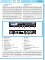 3
3
-
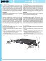 4
4
-
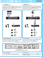 5
5
-
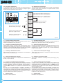 6
6
-
 7
7
-
 8
8
-
 9
9
-
 10
10
-
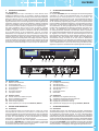 11
11
-
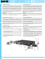 12
12
-
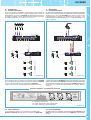 13
13
-
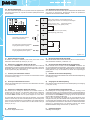 14
14
-
 15
15
-
 16
16
-
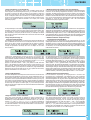 17
17
-
 18
18
-
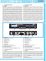 19
19
-
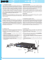 20
20
-
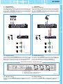 21
21
-
 22
22
-
 23
23
-
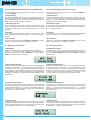 24
24
-
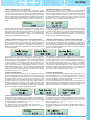 25
25
-
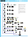 26
26
-
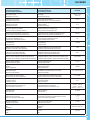 27
27
-
 28
28


in altre lingue
- English: Paso DLC9000 Owner's manual
- français: Paso DLC9000 Le manuel du propriétaire
- español: Paso DLC9000 El manual del propietario
- Deutsch: Paso DLC9000 Bedienungsanleitung
- Nederlands: Paso DLC9000 de handleiding
- português: Paso DLC9000 Manual do proprietário

