
EX2300-C and EX2300 Switches Hardware Guide
Modified: 2017-02-22
Copyright © 2017, Juniper Networks, Inc.

Juniper Networks, Inc.
1133 Innovation Way
Sunnyvale, California 94089
USA
408-745-2000
www.juniper.net
Copyright © 2017, Juniper Networks, Inc. All rights reserved.
Juniper Networks, Junos, Steel-Belted Radius, NetScreen, and ScreenOS are registered trademarks of Juniper Networks, Inc. in the United
States and other countries. The Juniper Networks Logo, the Junos logo, and JunosE are trademarks of Juniper Networks, Inc. All other
trademarks, service marks, registered trademarks, or registered service marks are the property of their respective owners.
Juniper Networks assumes no responsibility for any inaccuracies in this document. Juniper Networks reserves the right to change, modify,
transfer, or otherwise revise this publication without notice.
EX2300-C and EX2300 Switches Hardware Guide
Copyright © 2017, Juniper Networks, Inc.
All rights reserved.
The information in this document is current as of the date on the title page.
YEAR 2000 NOTICE
Juniper Networks hardware and software products are Year 2000 compliant. Junos OS has no known time-related limitations through the
year 2038. However, the NTP application is known to have some difficulty in the year 2036.
END USER LICENSE AGREEMENT
The Juniper Networks product that is the subject of this technical documentation consists of (or is intended for use with) Juniper Networks
software. Use of such software is subject to the terms and conditions of the End User License Agreement (“EULA”) posted at
http://www.juniper.net/support/eula.html. By downloading, installing or using such software, you agree to the terms and conditions of
that EULA.
Copyright © 2017, Juniper Networks, Inc.ii

Table of Contents
About the Documentation . . . . . . . . . . . . . . . . . . . . . . . . . . . . . . . . . . . . . . . . . . . xvii
Documentation and Release Notes . . . . . . . . . . . . . . . . . . . . . . . . . . . . . . . . xvii
Supported Platforms . . . . . . . . . . . . . . . . . . . . . . . . . . . . . . . . . . . . . . . . . . . . xvii
Documentation Conventions . . . . . . . . . . . . . . . . . . . . . . . . . . . . . . . . . . . . . xvii
Documentation Feedback . . . . . . . . . . . . . . . . . . . . . . . . . . . . . . . . . . . . . . . . xix
Requesting Technical Support . . . . . . . . . . . . . . . . . . . . . . . . . . . . . . . . . . . . . xx
Self-Help Online Tools and Resources . . . . . . . . . . . . . . . . . . . . . . . . . . . xx
Opening a Case with JTAC . . . . . . . . . . . . . . . . . . . . . . . . . . . . . . . . . . . . . xx
Part 1 Overview
Chapter 1 System Overview . . . . . . . . . . . . . . . . . . . . . . . . . . . . . . . . . . . . . . . . . . . . . . . . . . . 3
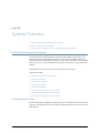
EX2300 Switches Hardware Overview . . . . . . . . . . . . . . . . . . . . . . . . . . . . . . . . . . . 3
EX2300 Switches First View . . . . . . . . . . . . . . . . . . . . . . . . . . . . . . . . . . . . . . . . 3
Uplink Ports . . . . . . . . . . . . . . . . . . . . . . . . . . . . . . . . . . . . . . . . . . . . . . . . . . . . . 4
Console Ports . . . . . . . . . . . . . . . . . . . . . . . . . . . . . . . . . . . . . . . . . . . . . . . . . . . 4
Cable Guard . . . . . . . . . . . . . . . . . . . . . . . . . . . . . . . . . . . . . . . . . . . . . . . . . . . . 4
Security Slot . . . . . . . . . . . . . . . . . . . . . . . . . . . . . . . . . . . . . . . . . . . . . . . . . . . . 5
Power over Ethernet (PoE) Ports . . . . . . . . . . . . . . . . . . . . . . . . . . . . . . . . . . . . 5
Front Panel of an EX2300 Switch . . . . . . . . . . . . . . . . . . . . . . . . . . . . . . . . . . . 5
Rear Panel of an EX2300 Switch . . . . . . . . . . . . . . . . . . . . . . . . . . . . . . . . . . . . 8
EX2300 Switch Models . . . . . . . . . . . . . . . . . . . . . . . . . . . . . . . . . . . . . . . . . . . . . . . 11
EX2300 Switch Hardware and CLI Terminology Mapping . . . . . . . . . . . . . . . . . . . 12
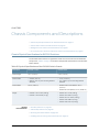
Chapter 2 Chassis Components and Descriptions . . . . . . . . . . . . . . . . . . . . . . . . . . . . . . . 15
Chassis Physical Specifications for EX2300 Switches . . . . . . . . . . . . . . . . . . . . . . 15
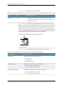
Chassis Status LEDs in EX2300 Switches . . . . . . . . . . . . . . . . . . . . . . . . . . . . . . . . 16
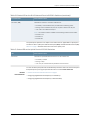
Management Port LEDs in EX2300 Switches . . . . . . . . . . . . . . . . . . . . . . . . . . . . . 18
RJ-45 Network Port LEDs and Uplink Port LEDs in EX2300 Switches . . . . . . . . . . 19
Chapter 3 Cooling System and Airflow . . . . . . . . . . . . . . . . . . . . . . . . . . . . . . . . . . . . . . . . 23
Cooling System and Airflow in an EX2300 Switch . . . . . . . . . . . . . . . . . . . . . . . . . 23
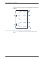
Airflow Direction in EX2300 Switches with 24 Ports with PoE Capability . . . 23
Airflow Direction in EX2300 Switches with 48 Ports with PoE Capability . . . 24
Airflow Direction in EX2300 Switches without PoE Capability . . . . . . . . . . . . 25
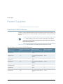
Chapter 4 Power Supplies . . . . . . . . . . . . . . . . . . . . . . . . . . . . . . . . . . . . . . . . . . . . . . . . . . . 27
Power Supply in EX2300 Switches . . . . . . . . . . . . . . . . . . . . . . . . . . . . . . . . . . . . . 27
iiiCopyright © 2017, Juniper Networks, Inc.

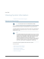
Chapter 5 Viewing System Information . . . . . . . . . . . . . . . . . . . . . . . . . . . . . . . . . . . . . . . 29
Dashboard for EX Series Switches . . . . . . . . . . . . . . . . . . . . . . . . . . . . . . . . . . . . . 29
Graphical Chassis Viewer . . . . . . . . . . . . . . . . . . . . . . . . . . . . . . . . . . . . . . . . . 30
System Information Panel . . . . . . . . . . . . . . . . . . . . . . . . . . . . . . . . . . . . . . . . . 31
Health Status Panel . . . . . . . . . . . . . . . . . . . . . . . . . . . . . . . . . . . . . . . . . . . . . 33
Capacity Utilization Panel . . . . . . . . . . . . . . . . . . . . . . . . . . . . . . . . . . . . . . . . . 35
Alarms Panel . . . . . . . . . . . . . . . . . . . . . . . . . . . . . . . . . . . . . . . . . . . . . . . . . . . 35
File System Usage . . . . . . . . . . . . . . . . . . . . . . . . . . . . . . . . . . . . . . . . . . . . . . . 36
Chassis Viewer . . . . . . . . . . . . . . . . . . . . . . . . . . . . . . . . . . . . . . . . . . . . . . . . . 36
Part 2 Site Planning, Preparation, and Specifications
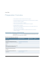
Chapter 6 Preparation Overview . . . . . . . . . . . . . . . . . . . . . . . . . . . . . . . . . . . . . . . . . . . . . . 51
Site Preparation Checklist for EX2300 Switches . . . . . . . . . . . . . . . . . . . . . . . . . . . 51
Environmental Requirements and Specifications for EX Series Switches . . . . . . . 53
General Site Guidelines . . . . . . . . . . . . . . . . . . . . . . . . . . . . . . . . . . . . . . . . . . . . . . 57
Site Electrical Wiring Guidelines . . . . . . . . . . . . . . . . . . . . . . . . . . . . . . . . . . . . . . . 57
Chassis Physical Specifications for EX2300 Switches . . . . . . . . . . . . . . . . . . . . . . 58
Rack Requirements . . . . . . . . . . . . . . . . . . . . . . . . . . . . . . . . . . . . . . . . . . . . . . . . . 59
Requirements for Mounting an EX2300 Switch On or Under a Desk or Other
Level Surface or On a Wall . . . . . . . . . . . . . . . . . . . . . . . . . . . . . . . . . . . . . . . . 60
Cabinet Requirements . . . . . . . . . . . . . . . . . . . . . . . . . . . . . . . . . . . . . . . . . . . . . . . 60
Clearance Requirements for Airflow and Hardware Maintenance for EX2300
Switches . . . . . . . . . . . . . . . . . . . . . . . . . . . . . . . . . . . . . . . . . . . . . . . . . . . . . . . 61
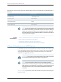
Chapter 7 Power Specifications and Requirements . . . . . . . . . . . . . . . . . . . . . . . . . . . . . 67
Power Specifications for EX2300 Switches . . . . . . . . . . . . . . . . . . . . . . . . . . . . . . 67
AC Power Cord Specifications for EX2300 Switches . . . . . . . . . . . . . . . . . . . . . . . 68
Calculating the EX Series Switch Fiber-Optic Cable Power Budget . . . . . . . . . . . 70
Calculating the EX Series Switch Fiber-Optic Cable Power Margin . . . . . . . . . . . . 70
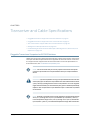
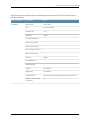
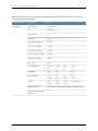
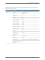
Chapter 8 Transceiver and Cable Specifications . . . . . . . . . . . . . . . . . . . . . . . . . . . . . . . . 73
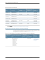
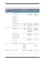
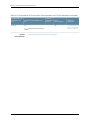
Pluggable Transceivers Supported on EX2300 Switches . . . . . . . . . . . . . . . . . . . . 73
Pluggable Transceivers Supported on EX Series Switches . . . . . . . . . . . . . . . . . . . 97
SFP+ Direct Attach Copper Cables for EX Series Switches . . . . . . . . . . . . . . . . . . 99
Cable Specifications . . . . . . . . . . . . . . . . . . . . . . . . . . . . . . . . . . . . . . . . . . . . . 99
Standards Supported by These Cables . . . . . . . . . . . . . . . . . . . . . . . . . . . . . 105
Management Cable Specifications . . . . . . . . . . . . . . . . . . . . . . . . . . . . . . . . . . . . 105
Understanding EX Series Switches Fiber-Optic Cable Signal Loss, Attenuation,
and Dispersion . . . . . . . . . . . . . . . . . . . . . . . . . . . . . . . . . . . . . . . . . . . . . . . . . 106
Signal Loss in Multimode and Single-Mode Fiber-Optic Cable . . . . . . . . . . 106
Attenuation and Dispersion in Fiber-Optic Cable . . . . . . . . . . . . . . . . . . . . . . 107
Chapter 9 Pinout Specifications . . . . . . . . . . . . . . . . . . . . . . . . . . . . . . . . . . . . . . . . . . . . . 109
Console Port Connector Pinout Information . . . . . . . . . . . . . . . . . . . . . . . . . . . . . 109
USB Port Specifications for an EX Series Switch . . . . . . . . . . . . . . . . . . . . . . . . . . 110
Mini-USB Port Pinout Specifications . . . . . . . . . . . . . . . . . . . . . . . . . . . . . . . . . . . . 111
RJ-45 Management Port Connector Pinout Information . . . . . . . . . . . . . . . . . . . . 112
RJ-45 Port, QSFP+ Port, SFP+ Port, and SFP Port Connector Pinout
Information . . . . . . . . . . . . . . . . . . . . . . . . . . . . . . . . . . . . . . . . . . . . . . . . . . . . 112
Copyright © 2017, Juniper Networks, Inc.iv
EX2300-C and EX2300 Switches Hardware Guide

SFP+ Uplink Port Connector Pinout Information for an EX2300 Switch . . . . . . . . 117
RJ-45 to DB-9 Serial Port Adapter Pinout Information . . . . . . . . . . . . . . . . . . . . . 118
Chapter 10 Planning the Virtual Chassis . . . . . . . . . . . . . . . . . . . . . . . . . . . . . . . . . . . . . . . 119
Planning EX2300 Virtual Chassis . . . . . . . . . . . . . . . . . . . . . . . . . . . . . . . . . . . . . . 119
Understanding EX2300 Virtual Chassis Hardware Configuration . . . . . . . . . . . . 120
Part 3 Initial Installation and Configuration
Chapter 11 Unpacking the Switch . . . . . . . . . . . . . . . . . . . . . . . . . . . . . . . . . . . . . . . . . . . . . 123
Unpacking an EX2300 Switch . . . . . . . . . . . . . . . . . . . . . . . . . . . . . . . . . . . . . . . . 123
Parts Inventory (Packing List) for an EX2300 Switch . . . . . . . . . . . . . . . . . . . . . . 124
Registering Products—Mandatory for Validating SLAs . . . . . . . . . . . . . . . . . . . . . 125
Chapter 12 Installing the Switch . . . . . . . . . . . . . . . . . . . . . . . . . . . . . . . . . . . . . . . . . . . . . . 127
Installing and Connecting an EX2300 Switch . . . . . . . . . . . . . . . . . . . . . . . . . . . . 127
Mounting an EX2300 Switch . . . . . . . . . . . . . . . . . . . . . . . . . . . . . . . . . . . . . . . . . 128
Mounting an EX2300 Switch on a Desk or Other Level Surface . . . . . . . . . . . . . . 129
Mounting an EX2300-C Switch Under a Desk or Other Level Surface by Using
Screws . . . . . . . . . . . . . . . . . . . . . . . . . . . . . . . . . . . . . . . . . . . . . . . . . . . . . . . . 131
Mounting an EX2300 Switch on Two Posts of a Rack or Cabinet . . . . . . . . . . . . 135
Mounting an EX2300 Switch on Four Posts of a Rack or Cabinet . . . . . . . . . . . . 137
Mounting an EX2300 Switch on a Wall . . . . . . . . . . . . . . . . . . . . . . . . . . . . . . . . . 141
Mounting an EX2300-C Switch on a Wall . . . . . . . . . . . . . . . . . . . . . . . . . . . . 141
Mounting an EX2300 Switch Except the EX2300-C Switch on a Wall . . . . . 144
Mounting an EX2300-C Switch on or Under a Surface Made of Ferrous
Material . . . . . . . . . . . . . . . . . . . . . . . . . . . . . . . . . . . . . . . . . . . . . . . . . . . . . . 149
Mounting an EX2300 Switch in a Recessed Position in a Rack or Cabinet . . . . . 153
Chapter 13 Connecting the Switch to Power . . . . . . . . . . . . . . . . . . . . . . . . . . . . . . . . . . . 155
Connecting Earth Ground to an EX Series Switch . . . . . . . . . . . . . . . . . . . . . . . . . 155
Parts and Tools Required for Connecting an EX Series Switch to Earth
Ground . . . . . . . . . . . . . . . . . . . . . . . . . . . . . . . . . . . . . . . . . . . . . . . . . . . 155
Special Instructions to Follow Before Connecting Earth Ground to a
Switch . . . . . . . . . . . . . . . . . . . . . . . . . . . . . . . . . . . . . . . . . . . . . . . . . . . . 158
Connecting Earth Ground to an EX Series Switch . . . . . . . . . . . . . . . . . . . . . 160
Connecting AC Power to an EX2300 Switch . . . . . . . . . . . . . . . . . . . . . . . . . . . . . 161
Connecting DC Power to an EX2300 Switch . . . . . . . . . . . . . . . . . . . . . . . . . . . . . 163
Chapter 14 Connecting the Switch to the Network . . . . . . . . . . . . . . . . . . . . . . . . . . . . . . 167
Connecting a Device to a Network for Out-of-Band Management . . . . . . . . . . . 167
Connecting a Device to a Management Console by Using an RJ-45
Connector . . . . . . . . . . . . . . . . . . . . . . . . . . . . . . . . . . . . . . . . . . . . . . . . . . . . 168
Connecting an EX2300 Switch to a Management Console by Using Mini-USB
Type-B Console Port . . . . . . . . . . . . . . . . . . . . . . . . . . . . . . . . . . . . . . . . . . . . 169
Connecting a Fiber-Optic Cable . . . . . . . . . . . . . . . . . . . . . . . . . . . . . . . . . . . . . . . 170
vCopyright © 2017, Juniper Networks, Inc.
Table of Contents

Chapter 15 Performing Initial Configuration . . . . . . . . . . . . . . . . . . . . . . . . . . . . . . . . . . . . 173
EX2300 Switch Default Configuration . . . . . . . . . . . . . . . . . . . . . . . . . . . . . . . . . . 173
Connecting and Configuring an EX Series Switch (CLI Procedure) . . . . . . . . . . . . 179
Connecting and Configuring an EX Series Switch (J-Web Procedure) . . . . . . . . . 182
Reverting to the Default Factory Configuration for the EX Series Switch . . . . . . . 186
Reverting to the Factory-Default Configuration by Using the LCD Panel . . . 187
Reverting to the Factory-Default Configuration by Using the request system
zeroize Command . . . . . . . . . . . . . . . . . . . . . . . . . . . . . . . . . . . . . . . . . . 188
Reverting to the Factory-Default Configuration by Using the load
factory-default Command . . . . . . . . . . . . . . . . . . . . . . . . . . . . . . . . . . . . 189
Reverting to the Factory-Default Configuration by Using the Factory
Reset/Mode button on EX2300 and EX3400 Switches . . . . . . . . . . . . 190
Part 4 Installing, Maintaining, and Replacing Components
Chapter 16 Replacing Transceiver . . . . . . . . . . . . . . . . . . . . . . . . . . . . . . . . . . . . . . . . . . . . . 193
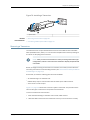
Installing a Transceiver . . . . . . . . . . . . . . . . . . . . . . . . . . . . . . . . . . . . . . . . . . . . . . 193
Removing a Transceiver . . . . . . . . . . . . . . . . . . . . . . . . . . . . . . . . . . . . . . . . . . . . . 195
Chapter 17 Maintaining and Replacing Fiber-Optic Cable . . . . . . . . . . . . . . . . . . . . . . . . 199
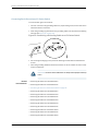
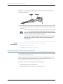
Connecting a Fiber-Optic Cable . . . . . . . . . . . . . . . . . . . . . . . . . . . . . . . . . . . . . . 199
Disconnecting a Fiber-Optic Cable from a Device . . . . . . . . . . . . . . . . . . . . . . . . 200
Maintaining Fiber-Optic Cables . . . . . . . . . . . . . . . . . . . . . . . . . . . . . . . . . . . . . . . 201
Chapter 18 Contacting Customer Support and Returning the Chassis or
Components . . . . . . . . . . . . . . . . . . . . . . . . . . . . . . . . . . . . . . . . . . . . . . . . . . . . 203
Returning an EX2300 Switch or Component for Repair or Replacement . . . . . . 203
Locating the Serial Number on an EX2300 Switch or Component . . . . . . . . . . . 203
Listing the Switch and Components Details with the CLI . . . . . . . . . . . . . . . 204
Locating the Chassis Serial Number ID Label on an EX2300 Switch . . . . . . 205
Contacting Customer Support to Obtain Return Material Authorization . . . . . . 205
Packing an EX2300 Switch or Component for Shipping . . . . . . . . . . . . . . . . . . . 206
Packing a Switch for Shipping . . . . . . . . . . . . . . . . . . . . . . . . . . . . . . . . . . . . 207
Packing Switch Components for Shipping . . . . . . . . . . . . . . . . . . . . . . . . . . . 207
Part 5 Troubleshooting
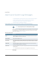
Chapter 19 Alarms and System Log Messages . . . . . . . . . . . . . . . . . . . . . . . . . . . . . . . . . . 211
Understanding Alarm Types and Severity Levels on EX Series Switches . . . . . . . 211
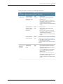
Chassis Component Alarm Conditions on EX2300 Switches . . . . . . . . . . . . . . . . 212
Checking Active Alarms with the J-Web Interface . . . . . . . . . . . . . . . . . . . . . . . . . 214
Monitoring System Log Messages . . . . . . . . . . . . . . . . . . . . . . . . . . . . . . . . . . . . . 215
Part 6 Safety and Compliance Information
Chapter 20 General Safety Guidelines and Warnings . . . . . . . . . . . . . . . . . . . . . . . . . . . . 223
General Safety Guidelines and Warnings . . . . . . . . . . . . . . . . . . . . . . . . . . . . . . . 223
Definitions of Safety Warning Levels . . . . . . . . . . . . . . . . . . . . . . . . . . . . . . . . . . . 224
Qualified Personnel Warning . . . . . . . . . . . . . . . . . . . . . . . . . . . . . . . . . . . . . . . . . 226
Warning Statement for Norway and Sweden . . . . . . . . . . . . . . . . . . . . . . . . . . . . 227
Copyright © 2017, Juniper Networks, Inc.vi
EX2300-C and EX2300 Switches Hardware Guide

Chapter 21 Fire Safety Requirements . . . . . . . . . . . . . . . . . . . . . . . . . . . . . . . . . . . . . . . . . 229
Fire Safety Requirements . . . . . . . . . . . . . . . . . . . . . . . . . . . . . . . . . . . . . . . . . . . . 229
Chapter 22 Installation Safety Guidelines and Warnings . . . . . . . . . . . . . . . . . . . . . . . . . 231
Installation Instructions Warning . . . . . . . . . . . . . . . . . . . . . . . . . . . . . . . . . . . . . . 231
Chassis Lifting Guidelines . . . . . . . . . . . . . . . . . . . . . . . . . . . . . . . . . . . . . . . . . . . 232
Restricted Access Warning . . . . . . . . . . . . . . . . . . . . . . . . . . . . . . . . . . . . . . . . . . . 232
Ramp Warning . . . . . . . . . . . . . . . . . . . . . . . . . . . . . . . . . . . . . . . . . . . . . . . . . . . . 234
Rack-Mounting and Cabinet-Mounting Warnings . . . . . . . . . . . . . . . . . . . . . . . . 234
Wall-Mounting Warnings for EX2300 Switches . . . . . . . . . . . . . . . . . . . . . . . . . . 238
Grounded Equipment Warning . . . . . . . . . . . . . . . . . . . . . . . . . . . . . . . . . . . . . . . 238
Chapter 23 Radiation and Laser Safety Guidelines and Warnings . . . . . . . . . . . . . . . . . 241
Laser and LED Safety Guidelines and Warnings . . . . . . . . . . . . . . . . . . . . . . . . . . 241
General Laser Safety Guidelines . . . . . . . . . . . . . . . . . . . . . . . . . . . . . . . . . . . 241
Class 1 Laser Product Warning . . . . . . . . . . . . . . . . . . . . . . . . . . . . . . . . . . . . 242
Class 1 LED Product Warning . . . . . . . . . . . . . . . . . . . . . . . . . . . . . . . . . . . . . 242
Laser Beam Warning . . . . . . . . . . . . . . . . . . . . . . . . . . . . . . . . . . . . . . . . . . . . 242
Radiation from Open Port Apertures Warning . . . . . . . . . . . . . . . . . . . . . . . . . . . 243
Chapter 24 Maintenance and Operational Safety Warnings . . . . . . . . . . . . . . . . . . . . . . 245
Maintenance and Operational Safety Guidelines and Warnings . . . . . . . . . . . . . 245
Battery Handling Warning . . . . . . . . . . . . . . . . . . . . . . . . . . . . . . . . . . . . . . . 245
Jewelry Removal Warning . . . . . . . . . . . . . . . . . . . . . . . . . . . . . . . . . . . . . . . 246
Lightning Activity Warning . . . . . . . . . . . . . . . . . . . . . . . . . . . . . . . . . . . . . . . 247
Operating Temperature Warning . . . . . . . . . . . . . . . . . . . . . . . . . . . . . . . . . . 248
Product Disposal Warning . . . . . . . . . . . . . . . . . . . . . . . . . . . . . . . . . . . . . . . 249
Chapter 25 Electrical Safety Guidelines and Warnings . . . . . . . . . . . . . . . . . . . . . . . . . . . 251
General Electrical Safety Guidelines and Warnings . . . . . . . . . . . . . . . . . . . . . . . . 251
Action to Take After an Electrical Accident . . . . . . . . . . . . . . . . . . . . . . . . . . . . . . 252
Prevention of Electrostatic Discharge Damage . . . . . . . . . . . . . . . . . . . . . . . . . . 253
AC Power Electrical Safety Guidelines . . . . . . . . . . . . . . . . . . . . . . . . . . . . . . . . . 254
AC Power Disconnection Warning . . . . . . . . . . . . . . . . . . . . . . . . . . . . . . . . . . . . . 255
DC Power Electrical Safety Guidelines for Switches . . . . . . . . . . . . . . . . . . . . . . 256
DC Power Disconnection Warning . . . . . . . . . . . . . . . . . . . . . . . . . . . . . . . . . . . . . 259
DC Power Grounding Requirements and Warning . . . . . . . . . . . . . . . . . . . . . . . . 260
DC Power Wiring Sequence Warning . . . . . . . . . . . . . . . . . . . . . . . . . . . . . . . . . . . 261
DC Power Wiring Terminations Warning . . . . . . . . . . . . . . . . . . . . . . . . . . . . . . . . 263
Multiple Power Supplies Disconnection Warning . . . . . . . . . . . . . . . . . . . . . . . . . 264
TN Power Warning . . . . . . . . . . . . . . . . . . . . . . . . . . . . . . . . . . . . . . . . . . . . . . . . . 264
Chapter 26 Agency Approvals and Compliance Statements . . . . . . . . . . . . . . . . . . . . . 267
Agency Approvals for EX Series Switches . . . . . . . . . . . . . . . . . . . . . . . . . . . . . . . 267
Compliance Statements for EMC Requirements for EX Series Switches . . . . . . 268
Canada . . . . . . . . . . . . . . . . . . . . . . . . . . . . . . . . . . . . . . . . . . . . . . . . . . . . . . 268
European Community . . . . . . . . . . . . . . . . . . . . . . . . . . . . . . . . . . . . . . . . . . 269
Israel . . . . . . . . . . . . . . . . . . . . . . . . . . . . . . . . . . . . . . . . . . . . . . . . . . . . . . . . 269
Japan . . . . . . . . . . . . . . . . . . . . . . . . . . . . . . . . . . . . . . . . . . . . . . . . . . . . . . . . 269
Korea . . . . . . . . . . . . . . . . . . . . . . . . . . . . . . . . . . . . . . . . . . . . . . . . . . . . . . . . 270
United States . . . . . . . . . . . . . . . . . . . . . . . . . . . . . . . . . . . . . . . . . . . . . . . . . 270
viiCopyright © 2017, Juniper Networks, Inc.
Table of Contents

FCC Part 15 Statement . . . . . . . . . . . . . . . . . . . . . . . . . . . . . . . . . . . . . . . . . . 270
Nonregulatory Environmental Standards . . . . . . . . . . . . . . . . . . . . . . . . . . . . 271
Compliance Statements for Acoustic Noise for EX Series Switches . . . . . . . . . . 272
Copyright © 2017, Juniper Networks, Inc.viii
EX2300-C and EX2300 Switches Hardware Guide

List of Figures
Part 1 Overview
Chapter 1 System Overview . . . . . . . . . . . . . . . . . . . . . . . . . . . . . . . . . . . . . . . . . . . . . . . . . . . 3
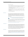
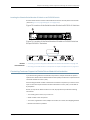
Figure 1: Front Panel of an EX2300-C Switch with 12 Gigabit Ethernet Ports with
PoE Capability . . . . . . . . . . . . . . . . . . . . . . . . . . . . . . . . . . . . . . . . . . . . . . . . . . . 6
Figure 2: Front Panel of an EX2300-C Switch with 12 Gigabit Ethernet Ports
without PoE Capability . . . . . . . . . . . . . . . . . . . . . . . . . . . . . . . . . . . . . . . . . . . . 6
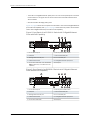
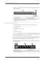
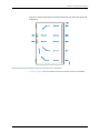
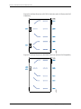
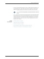
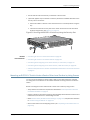
Figure 3: Front Panel of an EX2300 Switch with 24 Gigabit Ethernet Ports with
PoE Capability . . . . . . . . . . . . . . . . . . . . . . . . . . . . . . . . . . . . . . . . . . . . . . . . . . . 7
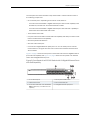
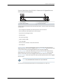
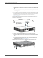
Figure 4: Front Panel of an EX2300 Switch with 48 Gigabit Ethernet Ports with
PoE Capability . . . . . . . . . . . . . . . . . . . . . . . . . . . . . . . . . . . . . . . . . . . . . . . . . . . 8
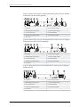
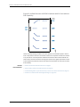
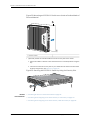
Figure 5: Rear Panel of an EX2300-C Switch with 12 Gigabit Ethernet Ports with
PoE Capability . . . . . . . . . . . . . . . . . . . . . . . . . . . . . . . . . . . . . . . . . . . . . . . . . . . 8
Figure 6: Rear Panel of an EX2300-C Switch with 12 Gigabit Ethernet Ports
without PoE Capability . . . . . . . . . . . . . . . . . . . . . . . . . . . . . . . . . . . . . . . . . . . . 9
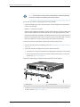
Figure 7: Rear Panel of an AC-Powered EX2300 Switch with 24 Gigabit Ethernet
Ports with PoE Capability . . . . . . . . . . . . . . . . . . . . . . . . . . . . . . . . . . . . . . . . . 10
Figure 8: Rear Panel of an AC-Powered EX2300 Switch with 24 Gigabit Ethernet
Ports without PoE Capability . . . . . . . . . . . . . . . . . . . . . . . . . . . . . . . . . . . . . . 10
Figure 9: Rear Panel of a DC-Powered EX2300 Switch with 24 Gigabit Ethernet
Ports . . . . . . . . . . . . . . . . . . . . . . . . . . . . . . . . . . . . . . . . . . . . . . . . . . . . . . . . . . 10
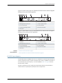
Figure 10: Rear Panelof an AC-Powered EX2300 Switch with 48 Gigabit Ethernet
Ports with PoE Capability . . . . . . . . . . . . . . . . . . . . . . . . . . . . . . . . . . . . . . . . . . 11
Figure 11: Rear Panel of an AC-Powered EX2300 Switch with 48 Gigabit Ethernet
Ports without PoE Capability . . . . . . . . . . . . . . . . . . . . . . . . . . . . . . . . . . . . . . . 11
Chapter 2 Chassis Components and Descriptions . . . . . . . . . . . . . . . . . . . . . . . . . . . . . . . 15
Figure 12: Chassis Status LEDs in EX2300-C Switches . . . . . . . . . . . . . . . . . . . . . . 16
Figure 13: Chassis Status LEDs in EX2300 Switches Except the EX2300-C
Switches . . . . . . . . . . . . . . . . . . . . . . . . . . . . . . . . . . . . . . . . . . . . . . . . . . . . . . . 16
Figure 14: LEDs on the Management Port on EX2300-C Switches . . . . . . . . . . . . . 18
Figure 15: LEDs on the Management Port on EX2300 Switches . . . . . . . . . . . . . . . 18
Figure 16: LEDs on RJ-45 Network Ports . . . . . . . . . . . . . . . . . . . . . . . . . . . . . . . . . 19
Figure 17: LEDs on the Uplink Ports in EX2300-C Switches . . . . . . . . . . . . . . . . . . 19
Figure18: LEDs on the Uplink Ports in an EX2300 Switches Except the EX2300-C
Switches . . . . . . . . . . . . . . . . . . . . . . . . . . . . . . . . . . . . . . . . . . . . . . . . . . . . . . . 19
Figure 19: Port Mode LEDs on EX2300 Switches . . . . . . . . . . . . . . . . . . . . . . . . . . 20
Chapter 3 Cooling System and Airflow . . . . . . . . . . . . . . . . . . . . . . . . . . . . . . . . . . . . . . . . 23
Figure 20: Airflow Direction in EX2300 Switches with 24 Ports with PoE
Capability . . . . . . . . . . . . . . . . . . . . . . . . . . . . . . . . . . . . . . . . . . . . . . . . . . . . . 24
ixCopyright © 2017, Juniper Networks, Inc.

Figure 21: Airflow Direction in EX2300 Switches with 48 Ports with PoE
Capability . . . . . . . . . . . . . . . . . . . . . . . . . . . . . . . . . . . . . . . . . . . . . . . . . . . . . 25
Figure 22: Airflow Direction in EX2300 Switches with 24 Ports without PoE
Capability . . . . . . . . . . . . . . . . . . . . . . . . . . . . . . . . . . . . . . . . . . . . . . . . . . . . . 26
Part 2 Site Planning, Preparation, and Specifications
Chapter 6 Preparation Overview . . . . . . . . . . . . . . . . . . . . . . . . . . . . . . . . . . . . . . . . . . . . . . 51
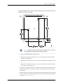
Figure 23: Clearance Requirements for Airflow and Hardware Maintenance for
EX2300-C Switches . . . . . . . . . . . . . . . . . . . . . . . . . . . . . . . . . . . . . . . . . . . . . 62
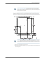
Figure 24: Clearance Requirements for Airflow and Hardware Maintenance for
EX2300 Switches Except EX2200-C Switches . . . . . . . . . . . . . . . . . . . . . . . . 62
Figure 25: Airflow Direction in EX2300 Switches with 24 Ports with PoE
Capability . . . . . . . . . . . . . . . . . . . . . . . . . . . . . . . . . . . . . . . . . . . . . . . . . . . . . 63
Figure 26: Airflow Direction in EX2300 Switches with 48 Ports with PoE
Capability . . . . . . . . . . . . . . . . . . . . . . . . . . . . . . . . . . . . . . . . . . . . . . . . . . . . . 64
Figure 27: Airflow Direction in EX2300 Switches without PoE Capability . . . . . . . 64
Chapter 7 Power Specifications and Requirements . . . . . . . . . . . . . . . . . . . . . . . . . . . . . 67
Figure 28: AC Plug Types . . . . . . . . . . . . . . . . . . . . . . . . . . . . . . . . . . . . . . . . . . . . . 69
Chapter 8 Transceiver and Cable Specifications . . . . . . . . . . . . . . . . . . . . . . . . . . . . . . . . 73
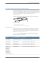
Figure 29: SFP+ Direct Attach Copper Cables for EX Series Switches . . . . . . . . . 99
Part 3 Initial Installation and Configuration
Chapter 12 Installing the Switch . . . . . . . . . . . . . . . . . . . . . . . . . . . . . . . . . . . . . . . . . . . . . . 127
Figure 30: Attaching a Cable Guard to an EX2300-C Switch . . . . . . . . . . . . . . . . 130
Figure 31: Securing the EX2300-C Switch by Using the Security Slot . . . . . . . . . . 131
Figure 32: Attaching a Cable Guard to an EX2300-C Switch . . . . . . . . . . . . . . . . 132
Figure33: Measurements for Installing Mounting Screws for Mounting EX2300-C
Switches Under a Desk or Other Level Surface by Using Screws . . . . . . . . . 133
Figure 34: Mounting the EX2300-C Switch Under a Desk or Other Level Surface
by Using Screws . . . . . . . . . . . . . . . . . . . . . . . . . . . . . . . . . . . . . . . . . . . . . . . . 134
Figure 35: Securing the EX2300-C Switch by Using the Security Slot . . . . . . . . . 134
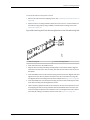
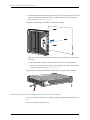
Figure 36: Attaching the Mounting Bracket Along the Front of the Switch . . . . . 136
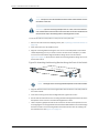
Figure 37: Mounting the Switch on Two Posts of a Rack . . . . . . . . . . . . . . . . . . . . 137
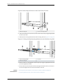
Figure 38: Attaching the Front-Mounting Bracket to the Side Mounting-Rail . . . 139
Figure 39: Attaching the Side Mounting-Rail to the Switch Chassis . . . . . . . . . . . 139
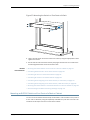
Figure 40: Mounting the Switch to the Front Posts of a Rack . . . . . . . . . . . . . . . 140
Figure 41: Sliding the Rear Mounting-Blades into the Side Mounting-Rail . . . . . . 140
Figure 42: Attaching a Cable Guard to an EX2300-C Switch . . . . . . . . . . . . . . . . 142
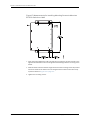
Figure 43: Measurements for Installing Mounting Screws for Mounting an
EX2300-C Switch on a Wall . . . . . . . . . . . . . . . . . . . . . . . . . . . . . . . . . . . . . . 143
Figure 44: Mounting an EX2300-C Switch on a Wall . . . . . . . . . . . . . . . . . . . . . . 144
Figure 45: Securing the EX2300-C Switch by Using the Security Slot . . . . . . . . . 144
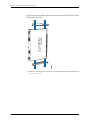
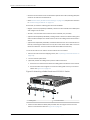
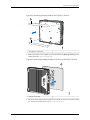
Figure 46: Attaching Wall-Mount Brackets to an EX2300 Switch Except the
EX2300-C Switch . . . . . . . . . . . . . . . . . . . . . . . . . . . . . . . . . . . . . . . . . . . . . . 146
Figure 47: Measurements for Installing Mounting Screws to Mount an EX2300
Switch on a Wall . . . . . . . . . . . . . . . . . . . . . . . . . . . . . . . . . . . . . . . . . . . . . . . 148
Copyright © 2017, Juniper Networks, Inc.x
EX2300-C and EX2300 Switches Hardware Guide

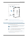
Figure 48: Mounting an EX2300 Switch on a Wall . . . . . . . . . . . . . . . . . . . . . . . . 149
Figure 49: Attaching a Cable Guard to an EX2300-C Switch . . . . . . . . . . . . . . . . 150
Figure 50: Attaching Rubber Pads to an EX2300-C Switch . . . . . . . . . . . . . . . . . . 151
Figure 51: Attaching the Magnet Mount Sheet to an EX2300-C Switch . . . . . . . . 151
Figure52: Mounting an EX2300-C Switch on or Under a Surface Made of Ferrous
Material . . . . . . . . . . . . . . . . . . . . . . . . . . . . . . . . . . . . . . . . . . . . . . . . . . . . . . 152
Figure 53: Securing the EX2300-C Switch by Using the Security Slot . . . . . . . . . 152
Chapter 13 Connecting the Switch to Power . . . . . . . . . . . . . . . . . . . . . . . . . . . . . . . . . . . 155
Figure 54: Connecting the Grounding Lug to a Switch Mounted on Four Posts of
a Rack . . . . . . . . . . . . . . . . . . . . . . . . . . . . . . . . . . . . . . . . . . . . . . . . . . . . . . . 159
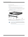
Figure 55: Connecting a Grounding Cable to an EX Series Switch . . . . . . . . . . . . 160
Figure 56: Connecting an AC Power Cord Retainer Clip to the AC Power Cord
Inlet on EX2300-C Switches . . . . . . . . . . . . . . . . . . . . . . . . . . . . . . . . . . . . . . 162
Figure 57: Connecting an AC Power Cord Retainer Clip to the AC Power Cord
Inlet on EX2300 Switches Except EX2300-C Switches . . . . . . . . . . . . . . . . . 162
Figure58: Connecting an AC Power Cord to the AC Power Cord Inlet on EX2300-C
Switches . . . . . . . . . . . . . . . . . . . . . . . . . . . . . . . . . . . . . . . . . . . . . . . . . . . . . 163
Figure 59: Connecting an AC Power Cord to the AC Power Cord Inlet on EX2300
Switches Except EX2300-C Switches . . . . . . . . . . . . . . . . . . . . . . . . . . . . . . 163
Figure 60: Securing the Ring Lugs On the Power Cables to the Terminals on the
DC Power Supply . . . . . . . . . . . . . . . . . . . . . . . . . . . . . . . . . . . . . . . . . . . . . . . 165
Chapter 14 Connecting the Switch to the Network . . . . . . . . . . . . . . . . . . . . . . . . . . . . . . 167
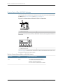
Figure 61: RJ-45 Connector on an Ethernet Cable . . . . . . . . . . . . . . . . . . . . . . . . . 167
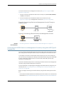
Figure 62: Connecting a Device to a Network for Out-of-Band Management . . . 168
Figure 63: RJ-45 Connector on an Ethernet Cable . . . . . . . . . . . . . . . . . . . . . . . . 168
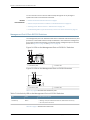
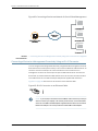
Figure 64: Connecting a Device to a Management Console Through a Console
Server . . . . . . . . . . . . . . . . . . . . . . . . . . . . . . . . . . . . . . . . . . . . . . . . . . . . . . . . 169
Figure 65: Connecting a Device Directly to a Management Console . . . . . . . . . . 169
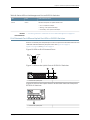
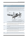
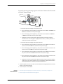
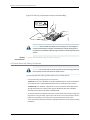
Figure 66: Connecting a Fiber-Optic Cable to an Optical Transceiver Installed
in a Device . . . . . . . . . . . . . . . . . . . . . . . . . . . . . . . . . . . . . . . . . . . . . . . . . . . . . 171
Chapter 15 Performing Initial Configuration . . . . . . . . . . . . . . . . . . . . . . . . . . . . . . . . . . . . 173
Figure 67: LCD Panel in an EX3200, EX4200, EX4500, EX4550, or EX8200
Switch . . . . . . . . . . . . . . . . . . . . . . . . . . . . . . . . . . . . . . . . . . . . . . . . . . . . . . . 184
Figure 68: LCD Panel in an EX4300 Switch . . . . . . . . . . . . . . . . . . . . . . . . . . . . . . 184
Figure 69: EX Series Switch LCD Panel . . . . . . . . . . . . . . . . . . . . . . . . . . . . . . . . . 188
Part 4 Installing, Maintaining, and Replacing Components
Chapter 16 Replacing Transceiver . . . . . . . . . . . . . . . . . . . . . . . . . . . . . . . . . . . . . . . . . . . . . 193
Figure 70: Installing a Transceiver . . . . . . . . . . . . . . . . . . . . . . . . . . . . . . . . . . . . . 195
Figure 71: Removing an SFP, SFP+, XFP, or a QSFP+ Transceiver . . . . . . . . . . . . . 197
Chapter 17 Maintaining and Replacing Fiber-Optic Cable . . . . . . . . . . . . . . . . . . . . . . . . 199
Figure 72: Connecting a Fiber-Optic Cable to an Optical Transceiver Installed in
a Device . . . . . . . . . . . . . . . . . . . . . . . . . . . . . . . . . . . . . . . . . . . . . . . . . . . . . 200
Chapter 18 Contacting Customer Support and Returning the Chassis or
Components . . . . . . . . . . . . . . . . . . . . . . . . . . . . . . . . . . . . . . . . . . . . . . . . . . . . 203
xiCopyright © 2017, Juniper Networks, Inc.
List of Figures

Figure 73: Location of the Serial Number ID Label on EX2300-C Switches . . . . 205
Figure 74: Location of the Serial Number ID Label on EX2300 Switches Except
EX2300-C Switches . . . . . . . . . . . . . . . . . . . . . . . . . . . . . . . . . . . . . . . . . . . . 205
Part 6 Safety and Compliance Information
Chapter 25 Electrical Safety Guidelines and Warnings . . . . . . . . . . . . . . . . . . . . . . . . . . . 251
Figure 75: Placing a Component into an Antistatic Bag . . . . . . . . . . . . . . . . . . . . 254
Copyright © 2017, Juniper Networks, Inc.xii
EX2300-C and EX2300 Switches Hardware Guide

List of Tables
About the Documentation . . . . . . . . . . . . . . . . . . . . . . . . . . . . . . . . . . . . . . . . . xvii
Table 1: Notice Icons . . . . . . . . . . . . . . . . . . . . . . . . . . . . . . . . . . . . . . . . . . . . . . . . xviii
Table 2: Text and Syntax Conventions . . . . . . . . . . . . . . . . . . . . . . . . . . . . . . . . . . xviii
Part 1 Overview
Chapter 1 System Overview . . . . . . . . . . . . . . . . . . . . . . . . . . . . . . . . . . . . . . . . . . . . . . . . . . . 3
Table 3: EX2300 Switch Models . . . . . . . . . . . . . . . . . . . . . . . . . . . . . . . . . . . . . . . . 12
Table 4: CLI Equivalents of Terms Used in Documentation for EX2300
Switches . . . . . . . . . . . . . . . . . . . . . . . . . . . . . . . . . . . . . . . . . . . . . . . . . . . . . . . 12
Chapter 2 Chassis Components and Descriptions . . . . . . . . . . . . . . . . . . . . . . . . . . . . . . . 15
Table 5: Physical Specifications of the EX2300 Switch Chassis . . . . . . . . . . . . . . . 15
Table 6: Chassis Status LEDs in an EX2300 Switch . . . . . . . . . . . . . . . . . . . . . . . . 16
Table 7: Link/Activity LED on the Management Port on EX2300 Switches . . . . . . 18
Table 8: Status LED on the Management Port on EX2300 Switches . . . . . . . . . . . 19
Table 9: Link/Activity LED on the RJ-45 Network Ports and the Uplink Ports in
EX2300 Switches . . . . . . . . . . . . . . . . . . . . . . . . . . . . . . . . . . . . . . . . . . . . . . . 20
Table 10: Status LED on the RJ-45 Network Ports in EX2300 Switches . . . . . . . . 20
Table 11: Status LED on the Uplink Ports in EX2300 Switches . . . . . . . . . . . . . . . . 21
Chapter 4 Power Supplies . . . . . . . . . . . . . . . . . . . . . . . . . . . . . . . . . . . . . . . . . . . . . . . . . . . 27
Table 12: Power Consumed by EX2300 Switches . . . . . . . . . . . . . . . . . . . . . . . . . . 27
Chapter 5 Viewing System Information . . . . . . . . . . . . . . . . . . . . . . . . . . . . . . . . . . . . . . . 29
Table 13: Details of a Virtual Chassis Member Switch . . . . . . . . . . . . . . . . . . . . . . 30
Table 14: Status of a Member Switch in a Virtual Chassis . . . . . . . . . . . . . . . . . . . . 31
Table 15: System Information . . . . . . . . . . . . . . . . . . . . . . . . . . . . . . . . . . . . . . . . . . 31
Table 16: Health Status . . . . . . . . . . . . . . . . . . . . . . . . . . . . . . . . . . . . . . . . . . . . . . 33
Table 17: Capacity Utilization . . . . . . . . . . . . . . . . . . . . . . . . . . . . . . . . . . . . . . . . . . 35
Table 18: Chassis Viewer for EX2200 Switches . . . . . . . . . . . . . . . . . . . . . . . . . . . 36
Table 19: Chassis Viewer for EX2200-C Switches . . . . . . . . . . . . . . . . . . . . . . . . . . 37
Table 20: Chassis Viewer for EX3200, EX3300, and EX4200 Switches . . . . . . . . 37
Table 21: Chassis Viewer for EX4300 Switches . . . . . . . . . . . . . . . . . . . . . . . . . . . 39
Table 22: Chassis Viewer for EX4500 Switches . . . . . . . . . . . . . . . . . . . . . . . . . . . 40
Table 23: Chassis Viewer for EX4550 Switches . . . . . . . . . . . . . . . . . . . . . . . . . . . . 41
Table 24: Chassis Viewer for EX4600 Switches . . . . . . . . . . . . . . . . . . . . . . . . . . . 43
Table 25: Chassis Viewer for EX6210 Switches . . . . . . . . . . . . . . . . . . . . . . . . . . . . 43
Table 26: Chassis Viewer for EX8208 Switches . . . . . . . . . . . . . . . . . . . . . . . . . . . 44
Table 27: Chassis Viewer for EX8216 Switches . . . . . . . . . . . . . . . . . . . . . . . . . . . . 46
Table 28: Chassis Viewer for XRE200 External Routing Engines . . . . . . . . . . . . . . 46
xiiiCopyright © 2017, Juniper Networks, Inc.

Part 2 Site Planning, Preparation, and Specifications
Chapter 6 Preparation Overview . . . . . . . . . . . . . . . . . . . . . . . . . . . . . . . . . . . . . . . . . . . . . . 51
Table 29: Site Preparation Checklist . . . . . . . . . . . . . . . . . . . . . . . . . . . . . . . . . . . . 51
Table 30: EX Series Switch Environmental Tolerances . . . . . . . . . . . . . . . . . . . . . . 53
Table 31: Site Electrical Wiring Guidelines . . . . . . . . . . . . . . . . . . . . . . . . . . . . . . . . 57
Table 32: Physical Specifications of the EX2300 Switch Chassis . . . . . . . . . . . . . 58
Table 33: Rack Requirements and Specifications . . . . . . . . . . . . . . . . . . . . . . . . . 59
Table 34: Cabinet Requirements and Specifications . . . . . . . . . . . . . . . . . . . . . . . 60
Chapter 7 Power Specifications and Requirements . . . . . . . . . . . . . . . . . . . . . . . . . . . . . 67
Table 35: AC Power Supply Electrical Specifications for EX2300 Switches . . . . . 67
Table 36: DC Power Supply Electrical Specifications for EX2300 Switches
(Except EX2300-C Switches) . . . . . . . . . . . . . . . . . . . . . . . . . . . . . . . . . . . . . 68
Table 37: AC Power Cord Specifications . . . . . . . . . . . . . . . . . . . . . . . . . . . . . . . . . 69
Table 38: Estimated Values for Factors Causing Link Loss . . . . . . . . . . . . . . . . . . 71
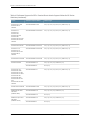
Chapter 8 Transceiver and Cable Specifications . . . . . . . . . . . . . . . . . . . . . . . . . . . . . . . . 73
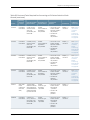
Table 39: Optical Interface Support and Copper Interface Support for SFP
Transceivers in EX2300 Switches . . . . . . . . . . . . . . . . . . . . . . . . . . . . . . . . . . . 75
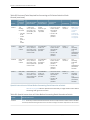
Table 40: Optical Interface Support for SFP+ Transceivers in EX2300
Switches . . . . . . . . . . . . . . . . . . . . . . . . . . . . . . . . . . . . . . . . . . . . . . . . . . . . . . 94
Table 41: Software Support for SFP+ Passive Direct Attach Copper Cables for
EX Series Switches . . . . . . . . . . . . . . . . . . . . . . . . . . . . . . . . . . . . . . . . . . . . . . 99
Table 42: SFP+ Direct Attach Copper Cable Specifications . . . . . . . . . . . . . . . . . 102
Table 43: Specifications of Cables to Connect to Management Devices . . . . . . . 106
Chapter 9 Pinout Specifications . . . . . . . . . . . . . . . . . . . . . . . . . . . . . . . . . . . . . . . . . . . . . 109
Table 44: Console Port Connector Pinout Information . . . . . . . . . . . . . . . . . . . . . 109
Table 45: Mini-USB Type-B Console Port Pinout Information . . . . . . . . . . . . . . . . 111
Table 46: RJ-45 Management Port Connector Pinout Information . . . . . . . . . . . . 112
Table 47: 10/100/1000BASE-T Ethernet Network Port Connector Pinout
Information . . . . . . . . . . . . . . . . . . . . . . . . . . . . . . . . . . . . . . . . . . . . . . . . . . . . 112
Table 48: SFP Network Port Connector Pinout Information . . . . . . . . . . . . . . . . . 113
Table 49: SFP+ Network Port Connector Pinout Information . . . . . . . . . . . . . . . . 114
Table 50: QSFP+ Network Port Connector Pinout Information . . . . . . . . . . . . . . . 115
Table 51: Connector Pinout Information for the 10-Gigabit Ethernet Uplink
Port . . . . . . . . . . . . . . . . . . . . . . . . . . . . . . . . . . . . . . . . . . . . . . . . . . . . . . . . . . 117
Table 52: RJ-45 to DB-9 Serial Port Adapter Pinout Information . . . . . . . . . . . . . 118
Part 3 Initial Installation and Configuration
Chapter 11 Unpacking the Switch . . . . . . . . . . . . . . . . . . . . . . . . . . . . . . . . . . . . . . . . . . . . . 123
Table 53: Parts List for EX2300 Switches . . . . . . . . . . . . . . . . . . . . . . . . . . . . . . . 124
Chapter 12 Installing the Switch . . . . . . . . . . . . . . . . . . . . . . . . . . . . . . . . . . . . . . . . . . . . . . 127
Table 54: EX2300 Switch Mounting Methods . . . . . . . . . . . . . . . . . . . . . . . . . . . . 128
Chapter 13 Connecting the Switch to Power . . . . . . . . . . . . . . . . . . . . . . . . . . . . . . . . . . . 155
Table 55: Parts and Tools Required for Connecting an EX Series Switch to Earth
Ground . . . . . . . . . . . . . . . . . . . . . . . . . . . . . . . . . . . . . . . . . . . . . . . . . . . . . . . 156
Copyright © 2017, Juniper Networks, Inc.xiv
EX2300-C and EX2300 Switches Hardware Guide

Table 56: Special Instructions to Follow Before Connecting Earth Ground to a
Switch . . . . . . . . . . . . . . . . . . . . . . . . . . . . . . . . . . . . . . . . . . . . . . . . . . . . . . . 158
Part 5 Troubleshooting
Chapter 19 Alarms and System Log Messages . . . . . . . . . . . . . . . . . . . . . . . . . . . . . . . . . . 211
Table 57: Alarm Terms . . . . . . . . . . . . . . . . . . . . . . . . . . . . . . . . . . . . . . . . . . . . . . . 211
Table 58: Alarm Conditions on EX2300 Switches . . . . . . . . . . . . . . . . . . . . . . . . . 213
Table 59: Summary of Key Alarm Output Fields . . . . . . . . . . . . . . . . . . . . . . . . . . 215
Table 60: Filtering System Log Messages . . . . . . . . . . . . . . . . . . . . . . . . . . . . . . . 216
Table 61: Viewing System Log Messages . . . . . . . . . . . . . . . . . . . . . . . . . . . . . . . . 218
xvCopyright © 2017, Juniper Networks, Inc.
List of Tables

Copyright © 2017, Juniper Networks, Inc.xvi
EX2300-C and EX2300 Switches Hardware Guide

About the Documentation
•
Documentation and Release Notes on page xvii
•
Supported Platforms on page xvii
•
Documentation Conventions on page xvii
•
Documentation Feedback on page xix
•
Requesting Technical Support on page xx
Documentation and Release Notes
To obtain the most current version of all Juniper Networks
®
technical documentation,
see the product documentation page on the Juniper Networks website at
http://www.juniper.net/techpubs/.
If the information in the latest release notes differs from the information in the
documentation, follow the product Release Notes.
Juniper Networks Books publishes books by Juniper Networks engineers and subject
matter experts. These books go beyond the technical documentation to explore the
nuances of network architecture, deployment, and administration. The current list can
be viewed at http://www.juniper.net/books.
Supported Platforms
For the features described in this document, the following platforms are supported:
•
EX2300
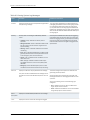
Documentation Conventions
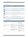
Table 1 on page xviii defines notice icons used in this guide.
xviiCopyright © 2017, Juniper Networks, Inc.

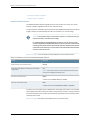
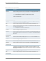
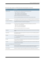
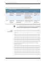
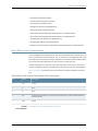
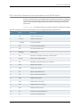
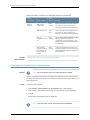
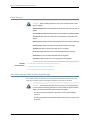
Table 1: Notice Icons
DescriptionMeaningIcon
Indicates important features or instructions.Informational note
Indicates a situation that might result in loss of data or hardware damage.Caution
Alerts you to the risk of personal injury or death.Warning
Alerts you to the risk of personal injury from a laser.Laser warning
Indicates helpful information.Tip
Alerts you to a recommended use or implementation.Best practice
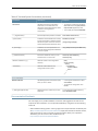
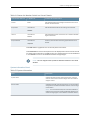
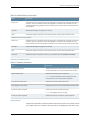
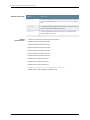
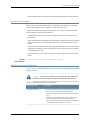
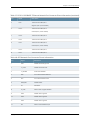
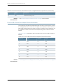
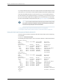
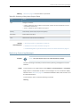
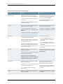
Table 2 on page xviii defines the text and syntax conventions used in this guide.
Table 2: Text and Syntax Conventions
ExamplesDescriptionConvention
To enter configuration mode, type the
configure command:
user@host> configure
Represents text that you type.Bold text like this
user@host> show chassis alarms
No alarms currently active
Represents output that appears on the
terminal screen.
Fixed-width text like this
•
A policy term is a named structure
that defines match conditions and
actions.
•
Junos OS CLI User Guide
•
RFC 1997, BGP Communities Attribute
•
Introduces or emphasizes important
new terms.
•
Identifies guide names.
•
Identifies RFC and Internet draft titles.
Italic text like this
Configure the machine’s domain name:
[edit]
root@# set system domain-name
domain-name
Represents variables (options for which
you substitute a value) in commands or
configuration statements.
Italic text like this
Copyright © 2017, Juniper Networks, Inc.xviii
EX2300-C and EX2300 Switches Hardware Guide

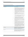
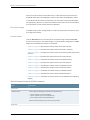
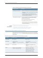
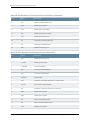
Table 2: Text and Syntax Conventions (continued)
ExamplesDescriptionConvention
•
To configure a stub area, include the
stub statement at the [edit protocols
ospf area area-id] hierarchy level.
•
The console port is labeled CONSOLE.
Represents names of configuration
statements, commands, files, and
directories; configuration hierarchy levels;
or labels on routing platform
components.
Text like this
stub <default-metric metric>;Encloses optional keywords or variables.< > (angle brackets)
broadcast | multicast
(string1 | string2 | string3)
Indicates a choice between the mutually
exclusive keywords or variables on either
side of the symbol. The set of choices is
often enclosed in parentheses for clarity.
| (pipe symbol)
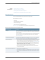
rsvp { # Required for dynamic MPLS onlyIndicates a comment specified on the
same line as the configuration statement
to which it applies.
# (pound sign)
community name members [
community-ids ]
Encloses a variable for which you can
substitute one or more values.
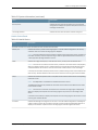
[ ] (square brackets)
[edit]
routing-options {
static {
route default {
nexthop address;
retain;
}
}
}
Identifies a level in the configuration
hierarchy.
Indention and braces ( { } )
Identifies a leaf statement at a
configuration hierarchy level.
; (semicolon)
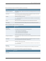
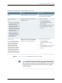
GUI Conventions
•
In the Logical Interfaces box, select
All Interfaces.
•
To cancel the configuration, click
Cancel.
Represents graphical user interface (GUI)
items you click or select.
Bold text like this
In the configuration editor hierarchy,
select Protocols>Ospf.
Separates levels in a hierarchy of menu
selections.
> (bold right angle bracket)
Documentation Feedback
We encourage you to provide feedback, comments, and suggestions so that we can
improve the documentation. You can provide feedback by using either of the following
methods:
•
Online feedback rating system—On any page of the Juniper Networks TechLibrary site
at http://www.juniper.net/techpubs/index.html, simply click the stars to rate the content,
and use the pop-up form to provide us with information about your experience.
Alternately, you can use the online feedback form at
http://www.juniper.net/techpubs/feedback/.
xixCopyright © 2017, Juniper Networks, Inc.
About the Documentation

•
E-mail—Send your commentsto techpubs-comments@juniper.net. Includethe document
or topic name, URL or page number, and software version (if applicable).
Requesting Technical Support
Technical product support is available through the Juniper Networks Technical Assistance
Center (JTAC). If you are a customer with an active J-Care or Partner Support Service
support contract, or are covered under warranty, and need post-sales technical support,
you can access our tools and resources online or open a case with JTAC.
•
JTAC policies—For a complete understanding of our JTAC procedures and policies,
review the JTAC User Guide located at
http://www.juniper.net/us/en/local/pdf/resource-guides/7100059-en.pdf.
•
Product warranties—For product warranty information, visit
http://www.juniper.net/support/warranty/.
•
JTAC hours of operation—The JTAC centers have resources available 24 hours a day,
7 days a week, 365 days a year.
Self-Help Online Tools and Resources
For quick and easy problem resolution, Juniper Networks has designed an online
self-service portal called the Customer Support Center (CSC) that provides you with the
following features:
•
Find CSC offerings: http://www.juniper.net/customers/support/
•
Search for known bugs: http://www2.juniper.net/kb/
•
Find product documentation: http://www.juniper.net/techpubs/
•
Find solutions and answer questions using our Knowledge Base: http://kb.juniper.net/
•
Download the latest versions of software and review release notes:
http://www.juniper.net/customers/csc/software/
•
Search technical bulletins for relevant hardware and software notifications:
http://kb.juniper.net/InfoCenter/
•
Join and participate in the Juniper Networks Community Forum:
http://www.juniper.net/company/communities/
•
Open a case online in the CSC Case Management tool: http://www.juniper.net/cm/
To verify service entitlementbyproduct serial number, use our Serial Number Entitlement
(SNE) Tool: https://tools.juniper.net/SerialNumberEntitlementSearch/
Opening a Case with JTAC
You can open a case with JTAC on the Web or by telephone.
•
Use the Case Management tool in the CSC at http://www.juniper.net/cm/.
•
Call 1-888-314-JTAC (1-888-314-5822 toll-free in the USA, Canada, and Mexico).
Copyright © 2017, Juniper Networks, Inc.xx
EX2300-C and EX2300 Switches Hardware Guide
La pagina si sta caricando...
La pagina si sta caricando...
La pagina si sta caricando...
La pagina si sta caricando...
La pagina si sta caricando...
La pagina si sta caricando...
La pagina si sta caricando...
La pagina si sta caricando...
La pagina si sta caricando...
La pagina si sta caricando...
La pagina si sta caricando...
La pagina si sta caricando...
La pagina si sta caricando...
La pagina si sta caricando...
La pagina si sta caricando...
La pagina si sta caricando...
La pagina si sta caricando...
La pagina si sta caricando...
La pagina si sta caricando...
La pagina si sta caricando...
La pagina si sta caricando...
La pagina si sta caricando...
La pagina si sta caricando...
La pagina si sta caricando...
La pagina si sta caricando...
La pagina si sta caricando...
La pagina si sta caricando...
La pagina si sta caricando...
La pagina si sta caricando...
La pagina si sta caricando...
La pagina si sta caricando...
La pagina si sta caricando...
La pagina si sta caricando...
La pagina si sta caricando...
La pagina si sta caricando...
La pagina si sta caricando...
La pagina si sta caricando...
La pagina si sta caricando...
La pagina si sta caricando...
La pagina si sta caricando...
La pagina si sta caricando...
La pagina si sta caricando...
La pagina si sta caricando...
La pagina si sta caricando...
La pagina si sta caricando...
La pagina si sta caricando...
La pagina si sta caricando...
La pagina si sta caricando...
La pagina si sta caricando...
La pagina si sta caricando...
La pagina si sta caricando...
La pagina si sta caricando...
La pagina si sta caricando...
La pagina si sta caricando...
La pagina si sta caricando...
La pagina si sta caricando...
La pagina si sta caricando...
La pagina si sta caricando...
La pagina si sta caricando...
La pagina si sta caricando...
La pagina si sta caricando...
La pagina si sta caricando...
La pagina si sta caricando...
La pagina si sta caricando...
La pagina si sta caricando...
La pagina si sta caricando...
La pagina si sta caricando...
La pagina si sta caricando...
La pagina si sta caricando...
La pagina si sta caricando...
La pagina si sta caricando...
La pagina si sta caricando...
La pagina si sta caricando...
La pagina si sta caricando...
La pagina si sta caricando...
La pagina si sta caricando...
La pagina si sta caricando...
La pagina si sta caricando...
La pagina si sta caricando...
La pagina si sta caricando...
La pagina si sta caricando...
La pagina si sta caricando...
La pagina si sta caricando...
La pagina si sta caricando...
La pagina si sta caricando...
La pagina si sta caricando...
La pagina si sta caricando...
La pagina si sta caricando...
La pagina si sta caricando...
La pagina si sta caricando...
La pagina si sta caricando...
La pagina si sta caricando...
La pagina si sta caricando...
La pagina si sta caricando...
La pagina si sta caricando...
La pagina si sta caricando...
La pagina si sta caricando...
La pagina si sta caricando...
La pagina si sta caricando...
La pagina si sta caricando...
La pagina si sta caricando...
La pagina si sta caricando...
La pagina si sta caricando...
La pagina si sta caricando...
La pagina si sta caricando...
La pagina si sta caricando...
La pagina si sta caricando...
La pagina si sta caricando...
La pagina si sta caricando...
La pagina si sta caricando...
La pagina si sta caricando...
La pagina si sta caricando...
La pagina si sta caricando...
La pagina si sta caricando...
La pagina si sta caricando...
La pagina si sta caricando...
La pagina si sta caricando...
La pagina si sta caricando...
La pagina si sta caricando...
La pagina si sta caricando...
La pagina si sta caricando...
La pagina si sta caricando...
La pagina si sta caricando...
La pagina si sta caricando...
La pagina si sta caricando...
La pagina si sta caricando...
La pagina si sta caricando...
La pagina si sta caricando...
La pagina si sta caricando...
La pagina si sta caricando...
La pagina si sta caricando...
La pagina si sta caricando...
La pagina si sta caricando...
La pagina si sta caricando...
La pagina si sta caricando...
La pagina si sta caricando...
La pagina si sta caricando...
La pagina si sta caricando...
La pagina si sta caricando...
La pagina si sta caricando...
La pagina si sta caricando...
La pagina si sta caricando...
La pagina si sta caricando...
La pagina si sta caricando...
La pagina si sta caricando...
La pagina si sta caricando...
La pagina si sta caricando...
La pagina si sta caricando...
La pagina si sta caricando...
La pagina si sta caricando...
La pagina si sta caricando...
La pagina si sta caricando...
La pagina si sta caricando...
La pagina si sta caricando...
La pagina si sta caricando...
La pagina si sta caricando...
La pagina si sta caricando...
La pagina si sta caricando...
La pagina si sta caricando...
La pagina si sta caricando...
La pagina si sta caricando...
La pagina si sta caricando...
La pagina si sta caricando...
La pagina si sta caricando...
La pagina si sta caricando...
La pagina si sta caricando...
La pagina si sta caricando...
La pagina si sta caricando...
La pagina si sta caricando...
La pagina si sta caricando...
La pagina si sta caricando...
La pagina si sta caricando...
La pagina si sta caricando...
La pagina si sta caricando...
La pagina si sta caricando...
La pagina si sta caricando...
La pagina si sta caricando...
La pagina si sta caricando...
La pagina si sta caricando...
La pagina si sta caricando...
La pagina si sta caricando...
La pagina si sta caricando...
La pagina si sta caricando...
La pagina si sta caricando...
La pagina si sta caricando...
La pagina si sta caricando...
La pagina si sta caricando...
La pagina si sta caricando...
La pagina si sta caricando...
La pagina si sta caricando...
La pagina si sta caricando...
La pagina si sta caricando...
La pagina si sta caricando...
La pagina si sta caricando...
La pagina si sta caricando...
La pagina si sta caricando...
La pagina si sta caricando...
La pagina si sta caricando...
La pagina si sta caricando...
La pagina si sta caricando...
La pagina si sta caricando...
La pagina si sta caricando...
La pagina si sta caricando...
La pagina si sta caricando...
La pagina si sta caricando...
La pagina si sta caricando...
La pagina si sta caricando...
La pagina si sta caricando...
La pagina si sta caricando...
La pagina si sta caricando...
La pagina si sta caricando...
La pagina si sta caricando...
La pagina si sta caricando...
La pagina si sta caricando...
La pagina si sta caricando...
La pagina si sta caricando...
La pagina si sta caricando...
La pagina si sta caricando...
La pagina si sta caricando...
La pagina si sta caricando...
La pagina si sta caricando...
La pagina si sta caricando...
La pagina si sta caricando...
La pagina si sta caricando...
La pagina si sta caricando...
La pagina si sta caricando...
La pagina si sta caricando...
La pagina si sta caricando...
La pagina si sta caricando...
La pagina si sta caricando...
La pagina si sta caricando...
La pagina si sta caricando...
La pagina si sta caricando...
La pagina si sta caricando...
La pagina si sta caricando...
La pagina si sta caricando...
La pagina si sta caricando...
La pagina si sta caricando...
La pagina si sta caricando...
La pagina si sta caricando...
La pagina si sta caricando...
La pagina si sta caricando...
La pagina si sta caricando...
La pagina si sta caricando...
La pagina si sta caricando...
La pagina si sta caricando...
La pagina si sta caricando...
La pagina si sta caricando...
La pagina si sta caricando...
La pagina si sta caricando...
La pagina si sta caricando...
La pagina si sta caricando...
La pagina si sta caricando...
La pagina si sta caricando...
La pagina si sta caricando...
La pagina si sta caricando...
La pagina si sta caricando...
La pagina si sta caricando...
La pagina si sta caricando...
La pagina si sta caricando...
La pagina si sta caricando...
La pagina si sta caricando...
La pagina si sta caricando...
La pagina si sta caricando...
La pagina si sta caricando...
La pagina si sta caricando...
La pagina si sta caricando...
La pagina si sta caricando...
La pagina si sta caricando...
La pagina si sta caricando...
La pagina si sta caricando...
La pagina si sta caricando...
La pagina si sta caricando...
La pagina si sta caricando...
-
 1
1
-
 2
2
-
 3
3
-
 4
4
-
 5
5
-
 6
6
-
 7
7
-
 8
8
-
 9
9
-
 10
10
-
 11
11
-
 12
12
-
 13
13
-
 14
14
-
 15
15
-
 16
16
-
 17
17
-
 18
18
-
 19
19
-
 20
20
-
 21
21
-
 22
22
-
 23
23
-
 24
24
-
 25
25
-
 26
26
-
 27
27
-
 28
28
-
 29
29
-
 30
30
-
 31
31
-
 32
32
-
 33
33
-
 34
34
-
 35
35
-
 36
36
-
 37
37
-
 38
38
-
 39
39
-
 40
40
-
 41
41
-
 42
42
-
 43
43
-
 44
44
-
 45
45
-
 46
46
-
 47
47
-
 48
48
-
 49
49
-
 50
50
-
 51
51
-
 52
52
-
 53
53
-
 54
54
-
 55
55
-
 56
56
-
 57
57
-
 58
58
-
 59
59
-
 60
60
-
 61
61
-
 62
62
-
 63
63
-
 64
64
-
 65
65
-
 66
66
-
 67
67
-
 68
68
-
 69
69
-
 70
70
-
 71
71
-
 72
72
-
 73
73
-
 74
74
-
 75
75
-
 76
76
-
 77
77
-
 78
78
-
 79
79
-
 80
80
-
 81
81
-
 82
82
-
 83
83
-
 84
84
-
 85
85
-
 86
86
-
 87
87
-
 88
88
-
 89
89
-
 90
90
-
 91
91
-
 92
92
-
 93
93
-
 94
94
-
 95
95
-
 96
96
-
 97
97
-
 98
98
-
 99
99
-
 100
100
-
 101
101
-
 102
102
-
 103
103
-
 104
104
-
 105
105
-
 106
106
-
 107
107
-
 108
108
-
 109
109
-
 110
110
-
 111
111
-
 112
112
-
 113
113
-
 114
114
-
 115
115
-
 116
116
-
 117
117
-
 118
118
-
 119
119
-
 120
120
-
 121
121
-
 122
122
-
 123
123
-
 124
124
-
 125
125
-
 126
126
-
 127
127
-
 128
128
-
 129
129
-
 130
130
-
 131
131
-
 132
132
-
 133
133
-
 134
134
-
 135
135
-
 136
136
-
 137
137
-
 138
138
-
 139
139
-
 140
140
-
 141
141
-
 142
142
-
 143
143
-
 144
144
-
 145
145
-
 146
146
-
 147
147
-
 148
148
-
 149
149
-
 150
150
-
 151
151
-
 152
152
-
 153
153
-
 154
154
-
 155
155
-
 156
156
-
 157
157
-
 158
158
-
 159
159
-
 160
160
-
 161
161
-
 162
162
-
 163
163
-
 164
164
-
 165
165
-
 166
166
-
 167
167
-
 168
168
-
 169
169
-
 170
170
-
 171
171
-
 172
172
-
 173
173
-
 174
174
-
 175
175
-
 176
176
-
 177
177
-
 178
178
-
 179
179
-
 180
180
-
 181
181
-
 182
182
-
 183
183
-
 184
184
-
 185
185
-
 186
186
-
 187
187
-
 188
188
-
 189
189
-
 190
190
-
 191
191
-
 192
192
-
 193
193
-
 194
194
-
 195
195
-
 196
196
-
 197
197
-
 198
198
-
 199
199
-
 200
200
-
 201
201
-
 202
202
-
 203
203
-
 204
204
-
 205
205
-
 206
206
-
 207
207
-
 208
208
-
 209
209
-
 210
210
-
 211
211
-
 212
212
-
 213
213
-
 214
214
-
 215
215
-
 216
216
-
 217
217
-
 218
218
-
 219
219
-
 220
220
-
 221
221
-
 222
222
-
 223
223
-
 224
224
-
 225
225
-
 226
226
-
 227
227
-
 228
228
-
 229
229
-
 230
230
-
 231
231
-
 232
232
-
 233
233
-
 234
234
-
 235
235
-
 236
236
-
 237
237
-
 238
238
-
 239
239
-
 240
240
-
 241
241
-
 242
242
-
 243
243
-
 244
244
-
 245
245
-
 246
246
-
 247
247
-
 248
248
-
 249
249
-
 250
250
-
 251
251
-
 252
252
-
 253
253
-
 254
254
-
 255
255
-
 256
256
-
 257
257
-
 258
258
-
 259
259
-
 260
260
-
 261
261
-
 262
262
-
 263
263
-
 264
264
-
 265
265
-
 266
266
-
 267
267
-
 268
268
-
 269
269
-
 270
270
-
 271
271
-
 272
272
-
 273
273
-
 274
274
-
 275
275
-
 276
276
-
 277
277
-
 278
278
-
 279
279
-
 280
280
-
 281
281
-
 282
282
-
 283
283
-
 284
284
-
 285
285
-
 286
286
-
 287
287
-
 288
288
-
 289
289
-
 290
290
-
 291
291
-
 292
292
-
 293
293
-
 294
294


Juniper EX2300 Series Manuale utente
- Tipo
- Manuale utente
- Questo manuale è adatto anche per
in altre lingue
- English: Juniper EX2300 Series User manual
Documenti correlati
-
Juniper EX4200-24T-DC Manuale utente
-
-
-
-
-
-
-
-
Juniper QFX5120-48Y-AFI2 Manuale utente
-
Altri documenti
-
DeLOCK 86640 Scheda dati
-
DeLOCK 86641 Scheda dati
-
DeLOCK 86642 Scheda dati
-
-
-
Yamaha SWR2311P-10G Manuale del proprietario
-
Intellinet 24-Port Gigabit Ethernet PoE Web-Managed Switch with 4 Gigabit Combo Base-T/SFP Ports Manuale utente
-
Panduit NK6PC5MY Scheda dati
-
 StarTech.com FIBLCST10 Scheda dati
-
