Alto RMX2408DFX Guida Rapida
- Categoria
- Amplificatore per strumenti musicali
- Tipo
- Guida Rapida

RMX2408DFX
QUICKSTART GUIDE
ENGLISH ( 3- 11 )
MANUAL DE INICIO RÁPIDO
ESPAÑOL ( 12 - 20 )
GUIDE D’UTILISATION RAPIDE
FRANÇAIS ( 21 – 29 )
GUIDA RAPIDA
ITALIANO ( 30 – 38 )
KURZANLEITUNG
DEUTSCH ( 39 – 47 )
SNELSTARTGIDS
NEDERLANDS ( 48 – 56 )


3
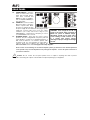
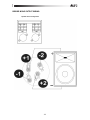
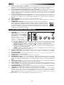
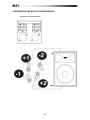
BOX CONTENTS
y RMX2408DFX
y Power cable
y Quickstart Guide
y Safety Instructions & Warranty Information booklet
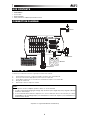
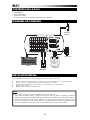
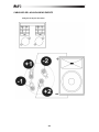
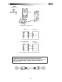
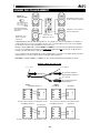
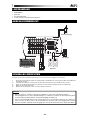
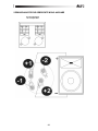
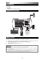
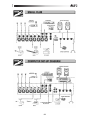
CONNECTION DIAGRAM
QUICK SETUP
Follow the procedure below to have a signal processed for each channel:
1. Set all channel levels to zero, set pan to the middle, set output to zero, and set EQ’s flat.
2. Connect your mic and then apply phantom power if your mic requires this.
3. Set the Master output level to no more than 75% and the Monitor output to no more than 50%.
4. Bring up the channel level.
5. Repeat steps 1 and 2 to setup more channels.
* Speakon is a registered trademark of Neutrik Corp.
Notes:
y Microphones, monitors, amplifier, speakers, cables, etc. are not included.
y To reduce electrical hum at high gain settings, keep the mixer's power supply away from your guitar cable and
the mixer's channel inputs.
y To use an external effects rack unit, compressor, etc., use a Y-cable (1/4" stereo to two 1/4" mono) to connect
the AUX OUT to the left and right inputs your external device. Connect the outputs of your external device to
the mixers Stereo Return.
Power
Monitors
Keyboard
Microphones
Headphones

4
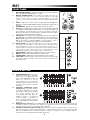
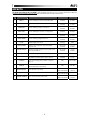
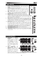
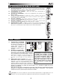
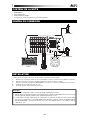
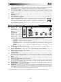
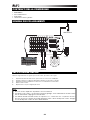
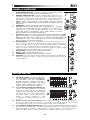
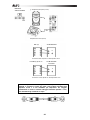
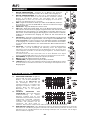
FRONT PANEL
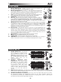
1. MIC/LINE MONO INPUTS – Connect a microphone or line level instrument
to these inputs using standard XLR or ¼” cable.
2. MIC/LINE STEREO INPUTS- These XLR and ¼” TRS connections are
organized in stereo pairs. If you connect only the left jack, the input will
operate in mono mode, (the mono signal will appear on both input
channels). You can use these inputs with a stereo keyboard, drum machine,
etc.
3. LEVEL – Adjusts the channel audio level (pre-fader and pre-EQ gain).
Adjust this so that the PEAK LED rarely lights up during the loudest parts of
the song.
4. CHANNEL BAL – Adjusts the channel's position in the stereo field.
5. AUX 1 Pre – This adjusts the prefader signal sent to the Monitor output and
is controllable using the Monitor Level knob. To use an external effects rack
unit, compressor, etc. with the mixer, you can use a Y-cable to connect the
AUX out to the input of your external device, and then connect the outputs
of the device to the Stereo Return of the amp.
6. AUX 2/FX Post- This adjusts the post fader signal which is sent through the
AUX OUT and is controllable with the DSP knobs to route the signal to the
MON or MAIN outputs. You can use a 1/4" TRS cable to connect the AUX
OUT to the input of an external amplifier or active monitor to create a
custom mix for onstage musicians with the mixer’s internal effects.
7-9. EQUALIZATION- You have three EQ controls for each mono and stereo
input channel each providing +/-15 dB of boost and cut. The signal will be
unaffected when the controls on the center position. You may use an
external equalizer to make up a mix properly but a master equalizer will not
have effect on a single channel and you may overload the signal easily.
Individual EQ will give you a much better control on single tracks.
7. HI EQ (TREBLE) – Adjusts the high (treble) frequencies of the channel.
8. MID EQ – Adjusts the mid-range frequencies of the channel.
9. LOW EQ (BASS) – Adjusts the low (bass) frequencies of the channel.
10. -20dB PAD- Pressing this button will attenuate the input signal by 20 dB.
This will give increased headroom and reduce the risk of distortion from
input signal peaks.
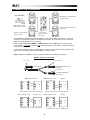
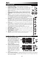
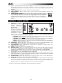
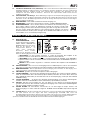
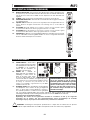
MASTER SECTION
11. STEREO GRAPHIC EQ: There are two
graphic EQs each with 9 adjustable
bands; one is for the MAIN mix and the
other is for the MONITOR mix. With the
faders you can boost or cut the
selected frequency by +/-15 dB at the
indicated frequencies. When all faders
are at the center position, the equalizer
is disabled.
12. FEEDBACK TERMINATOR Button
(MONITOR mix) - This button activates
the feedback detection in the monitor
signal path. Feedback will be identified
at a certain frequency when the
corresponding fader LED lights up.
Feedback produces an unpleasant
speaker "howling" or "whistling". In
order to eliminate feedback, turn down
the corresponding fader until feedback
disappears.
13. MONITOR LEVEL LED Display- This LED display will show you the monitor output level. Make sure that the
+10 LED only lights up occasionally. The optimal level is between -10 and 0 on the LED. If only the -30 LED
lights up or does not come on, your S/N ratio will be degraded.
14. FEEDBACK TERMINATOR Button (MAIN mix)- This button activates the feedback detection function in the
Main mix signal path. Feedback will be identified at a certain frequency when the corresponding fader LED
lights up. Feedback produces an unpleasant speaker "howling" or "whistling". In order to eliminate feedback,
turn down the corresponding fader until feedback disappears.
11
11
12
13
14
15
16
17
HI
HI
12kHz
12kHz
-15
MID
MID
2.5kHz
2.5kHz
-15
-15
PRE
PRE
AUX
AUX
SEND
SEND
+10dB
-
2 F X
POST
POST
-
+10dB
LEVEL
LEV EL
-
+10dB
-20dB PAD
-20dB PAD
LEFT
LEFT
RIGHT
RIGHT
BAL
BAL
10
7
8
9
5
6
4
3
LEVEL
LEVEL
LINE
LINE
BAL
BAL
MIC
MIC
BAL
BAL
MIC
MIC
BAL
BAL
LEVEL
LEVEL
1
NE W
1
NE W
1
1
1
2
2

5
18
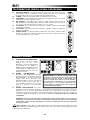
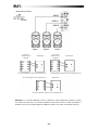
15. MAIN MIX LEVEL LED Display – This LED display will show you the Main mix output level. Make sure that the
+10 LED only lights up occasionally. The optimal level is between -10 and 0 on the LED. If only the -30 LED
lights up or does not come on your S/N ratio will be degraded.
16. MONITOR LEVEL – This adjusts the volume of the Monitor output.
17. MASTER LEVEL – This adjusts the overall volume of the MAIN output and HEADPHONE out.
18. PHANTOM POWER – This switch activates and deactivates phantom power. When
activated, phantom power supplies +48V to the XLR mic inputs and the LED above the switch
will be lit. Please note that most dynamic microphones do not require phantom power, while
most condenser microphones do. Consult your microphone’s documentation to find out
whether it needs phantom power.
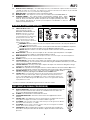
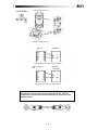
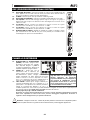
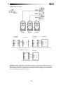
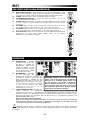
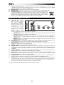
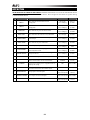
MASTER I/O (INPUT/OUTPUT)
19. AMPLIFIER Mode Switch- This
switch provides three modes:
MAIN/MAIN, MAIN/MONITOR and
BRIDGE. Select any one of these
modes to route the signals to the
corresponding jacks according to the
speaker panel connection. This
switch only affects the rear panel
outputs. The front panels outputs are
unaffected by this switch.
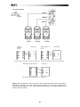
• MAIN/MAIN- When the switch is set to this, the amp will send the main mix to the rear panel Speakon
™
jacks or
the rear panel ¼” jacks.
• MAIN/MON- When the switch is set to this, the amp will send the main mix to the OUTPUT 1 Speakon
™
jack and 1/4'”jack. The monitor mix will be sent to the OUTPUT 2 Speakon
™ jack.
• BRIDGE- When the switch is set to this, the amp will send the main mix to the rear panel OUTPUT 2
Speakon
™ jack.
20. MAIN OUTPUTS – These 1/4" line level outputs can be connected to powered speakers or an amplifier
system. The level of these outputs is controlled by the Main Level knob.
21. MONITOR OUTPUT- This line level balanced output is used to connect the input of an external amplifier or
powered speaker.
22. PHONES – Connect your 1/4" stereo headphones to this output.
23. 2-TRACK INPUTS – Connect these to the outputs of an external sound source using standard stereo RCA
cables (sold separately). You can send this to channels 9/10 (using the 2-TRACK to 9/10 switch) or to the main
outputs (using the 2-TRACK TO MAIN switch).
24. 2-TRACK OUTPUTS – You may connect these outputs to the inputs of an external recording device using a
standard stereo RCA cable (sold separately).
25. AUX OUT- This outputs the line level signal sent from a channel’s AUX1 Pre knob to the Monitor Output. You
can use it to feed the inputs of another stereo multi-effects unit (using a Y-type cable sold separately).
26. STEREO RETURN- This stereo jack is used to route a stereo signal to the Main, Monitor
and Phones outputs by adjusting the FX TO MAIN and FX TO MON knobs.
27. 2-TRACK TO– If you position this switch to the left you will route the signal fed into the
TAPE IN sockets into CH9~10 path, and the signal will be affected by channel level
control, channel EQ, DSP send, and MAIN level control. Positioning this switch to the
right will route the TAPE IN signal into Main mix bus. In this case signal will be affected
only by Main level control.
* Speakon is a trademark of Neutrik® AG, registered in the U.S. and other countries.
DSP (DIGITAL SIGNAL PROCESSOR)
28. EFFECTS SELECTOR – Selects the effect that the mixer's internal effects processor will
apply to the various channels. Each channel can send different levels of audio to the
processor by adjusting their Aux 2/FX Post knobs.
29. FX MUTE – Press this button to mute/unmute the effects.
30. VARIATIONS SELECTOR – Selects the amount of the effect applied to the various
channels.
31. Clip/Mute LED – This LED flashes when the signal input into the digital multi-effect is too
strong. When the digital effect module is muted, the LED also lights up.
32. FX TO MON – This is used to control the volume of the processed signal sent to Monitor
mix, which can be varied from - to +10dB.
33. FX TO MAIN – This is used to control the volume of the processed signal sent to Main
mix bus, which can be varied from - to +10dB.
34. FOOTSWITCH – When a latching-style footswitch is connected to this jack with a 1/4"
TRS cable, it can be pressed to allow all channels to bypass the mixer's internal effects
processor.
FOOTSWITCH
FOOTSWITCH
100
FX TO MAIN
FX TO MAIN
100
28
31
29
30
32
33
34
20 20
21 22
23
23
24
24
25
26
27
19

6
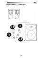
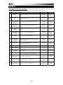
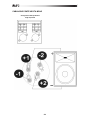
REAR PANEL
35. POWER SWITCH – Turns the
mixer on and off. Turn on the
mixer after all input devices
have been connected and
before you turn on amplifiers.
Turn off amplifiers before you
turn off the mixer.
36. POWER IN – Use the included
IEC power cable to connect the
mixer to a power outlet. While
the power is switched off, plug
the power supply into the mixer first, then plug the power
supply into a power outlet. Please check the voltage
available in your country and how the voltage for your
RMX2408DFX is configured before attempting to connect
your RMX2408DFX to the main AC.
37. SPEAKER JACKS – These jacks are used to connect
speakers. They are configured with 1/4" phone jacks and
4-way Speakon
™ connectors. For optimal performance, a
NL4 connector mated to a 4 conductor speaker cable
should be used. You can determine the signal that is
output to these jacks according to the setting of the
AMPLIFIER MODE select switch. See page 35 for setup diagrams.
Note: In order to avoid damage to the built-in amplifier, please pay attention to the allowed impedance
of the speaker. Very low load impedances may damage the amplifier. Look at the plate on the back of
your unit for reference.
!
Caution: Do not connect the rear panel speaker level ¼” outputs to anything other than a passive
loudspeaker. Connecting this output to a line line/Mic level input may damage your equipment.
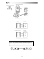
WARNING: Units bought in the US are
preset to US voltage. Units purchased in
EU/UK are preset to 220/240 voltage.
Adjustment should not be made unless
you’re traveling to other countries or are
in a country with varying voltage.
Selecting an improper voltage can damage
the unit.
35
36
37
37
37

7
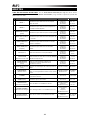
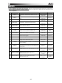
EFFECTS
TO HEAR THE EFFECTS ON A CHANNEL
: Use the Effects Selector to choose one of the effects below, adjust the
parameter with the Variations Selector, then turn up the Aux 2/FX Post knob for that channel.
# PRESET DESCRIPTION PARAMETER RANGE
1 VOCAL 1 Reverb, simulating a room with a small delay time.
Decay time
Pre-delay
0.8~1.1s
0~79ms
2 VOCAL 2
Reverb, simulating a small space with a small delay
time.
Decay time
Pre-delay
0.8~2.5s
0~79ms
3 LARGE HALL Reverb, simulating a large acoustic space.
Decay time
Pre-delay
3.6~5.4s
23~55ms
4 SMALL HALL Reverb, simulating the acoustics of a stage space.
Decay time
Pre-delay
1.0~2.9s
20~45ms
5 LARGE ROOM Reverb, simulating a studio with many early reflections.
Decay time
Pre-delay
2.9~4.5s
23~55ms
6 SMALL ROOM Reverb, simulating a bright studio room.
Decay time
Pre-delay
0.7~2.1s
20~45ms
7 PLATE Simulates bright plate reverb.
Decay time
Pre-delay
0.6~6.1s
10ms
8 TAPE REVERB
Simulates classic tape delay created by multiple
playback heads.
Decay time
Pre-delay
1.3~5.4
0~84ms
9 SPRING REVERB
Simulates the lightly stretched sound of spring reverb
from analog transducers.
Decay time
Pre-delay
1.3~5.4s
0~84ms
10 MONO DELAY Reproduces the signal after a small period of time. Delay period 60~650ms
11 STEREO DELAY
Reproduces the signal after a small period of time with a
slight difference between the two stereo channels.
Delay period
Feedback
210~400ms
37~73%
12 FLANGER
Classic stereo flanging effect, similar to a jet plane
taking off.
Rate 0.16~2.79Hz
13 CHORUS
Simulates the full, complex, watery sound of several
instruments playing the same thing.
Rate 0.5~5Hz
14 REVERB+DELAY Delay effect with room reverb.
Delay period
Reverse decay time
211~375ms
1.0~2.9s
15 REVERB+FLANGER Stereo flanger effect with room reverb.
Flanger rate
Reverse decay time
0.16~2.52Hz
16 REVERB+CHORUS Stereo chorus effect with room reverb.
Chorus rate
Reverse decay time
0.5~4.74Hz
1.5~2.9s

8
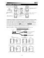
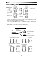
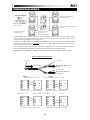
CONNECTION DIAGRAMS
AMP(R) Speakon™ Jac
k
Speaker
AMP(R) Speakon™ Jack Speaker
Right Speakon™ Connector to Right Speaker
Left Speakon™ Connector to Left Speaker
Left Speakon™ Connector to Right Speaker
AMP
(
L
)
S
p
eakon™ Jac
k
AMP(L) Speakon™ Jack
Speaker
Right Speakon™ Connector to Left Speaker
Speaker™ Jack
Speaker- 4 ohm minimum load
p
er s
p
eaker
Use either the
Speakon™ jacks or
phone jacks
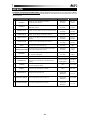
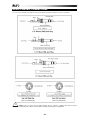
The RMX 2408 is equipped with NL4 type Speakon™ output jacks. When connected to a 4 conductor
speaker wire, 2-Channels of audio can be carried on one cable. NL4 connectors can also be used to
bridge two amplifier channels for mono output.
When using the RMX 2408 in 500W X 2 + 500W X 2 mode, the L and R Speakon™ outputs can be
used to power a stereo pair
of speakers per L and R output jack. (In this mode, it is possible to power 2
stereo speaker pairs.)
To drive a pair of speakers at the L or R Speakon™ outputs, use a Speakon™ NL4 to Speakon™ NL2
splitter cable. The diagram below illustrates Speakon™ splitter wiring.
Note: In 500W X 2 + 500W X 2 mode, the minimum s
p
eaker load is 4 Ohms
p
er channel.
AMPLIFER MODE
Speakon* 4 pole to 2 pole splitter
1+, 1-, 2+,2-
To Speaker Speakon™ In
Connector
1+,1- (CH -1)
2+,2- (CH -2)
To Speaker Speakon™
In Connector
From Amp (L)
Speaker- 4 ohm minimum
load
p
er s
p
eaker
Main Speaker- 4 ohm minimum
load
p
er s
p
eaker
Main Speaker- 4 ohm
minimum load
p
er s
p
eaker

9
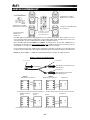
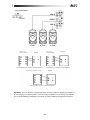
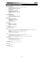
Note: ¼” Jacks are not used in this configuration. When bridging outputs,
NL4 Speakon
* connectors attached to 4 conductor speaker cables are
required. For proper Speakon
* connector/cable wiring, please refer to the
diagrams above.
AMP (R)
SPEAKER
Right Speakon™ Connector to Mono Speaker
AMP (L) Speakon™
Jack
SPEAKER
Left Speakon™ Connector to Mono Speaker
Monitor S
p
eaker
(
8 ohms
)
Main S
p
eaker
(
8ohms
)
AMPLIFER MODE

10
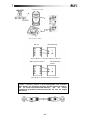
Note: The Mono Speakon™ jack is used with this configuration only. When using the Mono out jack, an
NL4 Speakon
™ connector attached to a 4 pole conductor speaker cable is required. For proper
Speakon
™ connector/cable wiring, please refer to the diagrams above.
Left Speakon™ Connector to Left Speaker
AMP (Mono) Speakon™ Jack
Mono Speakon™ Connector to Mono Speaker
AMP (R)
Speakon™ Jack
Speaker
AMP (L)
Speakon™ Jack
Speaker
Right Speakon™ Connector to Right Speaker
Speaker
500
W
500 W
1000 W
4 Ohm
8
O
hm 4 Ohm
AMPLIFER MODE

11
BRIDGE MONO OUTPUT WIRING
Speaker Pinout Configuration

12
CONTENIDO DE LA CAJA
y RMX2408DFX
y Cable de alimentación
y Guía de inicio rápido
y Folleto de instrucciones de seguridad e información sobre la garantía
DIAGRAMA DE CONEXIÓN
INSTALACIÓN RÁPIDA
Siga el procedimiento indicado a continuación para procesar una señal por cada canal:
1. Ajuste los niveles de todos los canales a cero, el paneo (pan) al centro, la salida a cero y la ecualización plana.
2. Conecte su micrófono y aplique alimentación fantasma si su micrófono lo requiere.
3. Ajuste el nivel de salida maestro a no más del 75% y la salida de monitor a no más del 50%.
4. Aumente el nivel del canal.
5. Repita los pasos 1 y 2 para instalar más canales.
Notas:
y No se incluyen micrófonos, monitores, amplificador, altavoces, cables, etc.
y Para reducir el zumbido eléctrico cuando se usan ajustes altos de ganancia, mantenga la fuente de
alimentación del mezclador alejada del cable de su guitarra y de las entradas de los canales del mezclador.
y Para usar una unidad de rack de efectos, compresor, etc. externos, utilice un cable en “Y” (estéreo de 1/4"a
dos mono de 1/4") para conectar la salida AUX a las entradas izquierda y derecha de su dispositivo externo.
Conecte las salidas de su dispositivo externo a Stereo Return (Retorno estéreo) del mezclador.
Suministro
eléctrico
Altavoces del
auditorio
Teclado
Micrófonos
Auriculares

13
PANEL FRONTAL
1. ENTRADAS MONO DE MICRÓFONO/LÍNEA – Conecte a estas entradas un
micrófono o un instrumento de nivel de línea usando cable XLR o de ¼”
estándar.
2. ENTRADAS ESTÉREO DE MICRÓFONO/LÍNEA- Estas conexiones XLR y ¼”
TRS están organizadas en pares estéreo. Si conecta sólo el conector
izquierdo, la entrada funciona en modo mono (la señal mono aparece en
ambos canales de entrada). Puede usar estas entradas con un teclado
estéreo, caja de ritmos, etc.
3. NIVEL – Ajusta el nivel de audio del canal (ganancia pre-fader y pre-
ecualización). Ajuste este control de modo que el LED PEAK (Pico) se
encienda muy pocas veces durante las partes más sonoras del tema.
4. BALANCE DE CANAL – Ajusta la posición del canal en el campo estéreo.
5. AUX 1 Pre – Ajusta la señal previa al fader enviada a la salida de monitor y es
controlable usando la perilla de nivel de monitor. Para usar una unidad de rack de efectos,
compresor, etc. externo con el mezclador, puede usar un cable en “Y” a fin de conectar la
salida AUX a la entrada de su dispositivo externo y luego conectar las salidas de este
último a la entrada de retorno del amplificador.
6. AUX 2/FX Post- Este control ajusta la señal post-fader que se envía por la salida AUX y se
controla con las perillas DSP para aplicar la señal a las salidas MON (Monitor) o MAIN
(Principal). Puede usar un cable TRS de 1/4" para conectar la SALIDA AUX a la entrada de
un amplificador externo o monitor activo a fin de crear una mezcla personalizada para los
músicos en el escenario con los efectos internos del mezclador.
7-9- ECUALIZACIÓN - Se dispone de tres controles de ecualizador para cada canal de entrada
mono y estéreo, cada uno de los cuales proporciona +/-15 dB de refuerzo y corte. La señal
no es afectada cuando los controles están en la posición central. Puede usar un
ecualizador externo para armar una mezcla correctamente, pero un ecualizador maestro
no tiene efecto sobre un solo canal y es muy fácil que sobrecargue la señal. Un
ecualizador individual le permite un control mucho mejor sobre las pistas individuales.
7. ECUALIZADOR DE ALTOS (AGUDOS) – Ajusta las frecuencias altas (agudos) del canal.
8. ECUALIZADOR DE MEDIOS – Ajusta las frecuencias medias del canal.
9. ECUALIZADOR DE BAJOS (GRAVES) – Ajusta las frecuencias bajas (graves) del canal.
10. ATENUADOR DE -20 dB- Al pulsar este botón, la señal de entrada se atenúa 20 dB. De
esta forma aumenta el margen de carga y se reduce el riesgo de distorsión en los picos de
la señal de entrada.
SECCIÓN MAESTRA
11. ECUALIZADOR GRÁFICO
ESTÉREO – Se dispone de dos
ecualizadores gráficos, con 9 bandas
ajustables cada uno; uno para la
mezcla PRINCIPAL y otro para la
mezcla de MONITOR. Con los faders,
es posible reforzar o cortar la
frecuencia seleccionada en +/-15 dB
en las frecuencias indicadas. Cuando
todos los faders están en la posición
central, el ecualizador está
desactivado.
12. Botón TERMINADOR DE
REALIMENTACIÓN (mezcla de
MONITOR) – Este botón activa la
detección de realimentación en la ruta
de señal de monitor. Se identifica la
realimentación en una cierta
frecuencia cuando se enciende el
LED del fader correspondiente. La
realimentación produce un desagradable "aullido" o "silbido" del altavoz. Para eliminar la realimentación,
disminuya el ajuste del fader correspondiente hasta que desaparezca.
11
11
12
13
14
15
16
17
HI
HI
12kHz
12kHz
-15
MID
MID
2.5kHz
2.5kHz
-15
-15
PRE
PRE
AUX
AUX
SEND
SEND
+10dB
-
2 F X
POST
POST
-
+10dB
LEVEL
LEVEL
-
+10dB
-20dB PAD
-20dB PAD
LEFT
LEFT
RIGHT
RIGHT
BAL
BAL
10
7
8
9
5
6
4
3
LEVEL
LEV EL
LINE
LINE
BAL
BAL
MIC
MIC
BAL
BAL
MIC
MIC
BAL
BAL
LEVEL
LEV EL
1
NEW
1
NEW
1
1
1
2
2

14
18
13. Pantalla de LED DE NIVEL DE MONITOR – Esta pantalla de LED muestra el nivel de salida de monitor.
Asegúrese de que el LED de +10 sólo se encienda ocasionalmente. El nivel óptimo está entre -10 y 0 en los
LED. Si sólo se enciende el LED de -30 LED o no se encienden, la relación señal/ruido se degrada.
14. Botón TERMINADOR DE REALIMENTACIÓN (mezcla PRINCIPAL) – Este botón activa la detección de
realimentación en la ruta de señal de la mezcla principal. Se identifica la realimentación en una cierta
frecuencia cuando se enciende el LED del fader correspondiente. La realimentación produce un desagradable
"aullido" o "silbido" del altavoz. Para eliminar la realimentación, disminuya el ajuste del fader correspondiente
hasta que desaparezca.
15. Pantalla de LED DE NIVEL de la mezcla PRINCIPAL – Esta pantalla de LED muestra el nivel de salida de la
mezcla principal. Asegúrese de que el LED de +10 sólo se encienda ocasionalmente. El nivel óptimo está
entre -10 y 0 en los LED. Si sólo se enciende el LED de -30 LED o no se encienden, la relación señal/ruido se
degrada.
16. NIVEL DE MONITOR – Este control ajusta el volumen de la salida de monitor.
17. NIVEL MAESTRO– Este control ajusta el volumen general de la salida PRINCIPAL y la salida para
AURICULARES.
18. ALIMENTACIÓN FANTASMA – Este interruptor activa y desactiva la alimentación fantasma.
Cuando está activada, la alimentación fantasma suministra +48 V a las entradas de micrófono
XLR y el LED que está arriba del interruptor se enciende. Tenga en cuenta que la mayoría de
los micrófonos dinámicos no requieren alimentación fantasma, mientras que la mayoría de los
micrófonos de condensador la requieren. Consulte la documentación de su micrófono para
averiguar si necesita alimentación fantasma.
E/S (ENTRADAS/SALIDAS) MAESTRAS
19. Conmutador de modo del
AMPLIFICADOR- Este conmutador
proporciona tres modos: MAIN/MAIN
(Principal/Principal), MAIN/MONITOR
(Principal/Monitor) y BRIDGE
(Puente). Seleccione uno de estos
modos para aplicar las señales a los
conectores correspondientes de
acuerdo a la conexión del panel de
altavoces. Este conmutador sólo afecta a las salidas del panel trasero. No afecta a las salidas del panel frontal.
• PRINCIPAL/PRINCIPAL- Cuando el conmutador se ajusta a este modo, el amplificador envía la mezcla
principal a los conectores Speakon
™ del panel trasero o a los conectores de ¼” del panel trasero.
• PRINCIPAL/MONITOR- Cuando el conmutador se ajusta a este modo, el amplificador envía la mezcla
principal al conector Speakon
™ OUTPUT 1 (Salida 1) y al conector de 1/4”. La mezcla de monitor se
envía al conector Speakon
™ OUTPUT 2.
• PUENTE - Cuando el conmutador se ajusta a este modo, el amplificador envía la mezcla principal al
conector Speakon
™ OUTPUT 2 del panel trasero.
20. SALIDAS PRINCIPALES – Estas salidas de nivel de línea de 1/4" se pueden conectar a altavoces
alimentados o a un sistema de amplificadores. El nivel de estas salidas está controlado por la perilla Main
Level (Nivel principal).
21. SALIDA DE MONITOR - Esta salida balanceada de nivel de línea se usa para conectar la entrada de un
amplificador externo o altavoz alimentado.
22. AURICULARES – Conecte sus auriculares estéreo de ¼” a esta salida.
23. ENTRADAS DE 2 PISTAS – Conecte estas entradas a las salidas de una fuente de sonido externa mediante
cables RCA estéreo estándar (se venden por separado). Puede enviar estas entradas a los canales 9/10
(usando el conmutador 2-TRACK TO 9/10) o a las salidas principales (usando el conmutador 2-TRACK TO
MAIN).
24. SALIDAS DE 2 PISTAS – Es posible conectar estas salidas a las entradas de un dispositivo de grabación
externo usando un cable RCA estéreo estándar (se vende por separado).
25. SALIDA AUXILIAR- Esta salida aplica la señal de nivel de línea enviada desde la perilla AUX1 Pre de un
canal a la salida de monitor. Puede usarla para aplicarla a las entradas de otra unidad multiefectos estándar
(con un cable tipo Y que se vende por separado).
26. RETORNO ESTÉREO- Este conector estéreo se usa para aplicar una señal estéreo a las salidas PRINCIPAL,
de MONITOR y de AURICULARES ajustando las perillas FX TO MAIN y FX TO MON.
27. 2 PISTAS A– Si posiciona este conmutador a la izquierda, dirige la señal aplicada a los zócalos TAPE IN
(Entrada de cinta) a la ruta CH9~10, y la señal será afectada por el control de nivel del canal, el ecualizador
del canal, el envío de DSP y el control de nivel PRINCIPAL. Si se posiciona este conmutador a la derecha, se
dirige la señal TAPE IN al bus de mezcla principal. En este caso, la señal es afectada sólo por el control de
nivel principal.
* Speakon™ es una marca comercial de Neutrik® AG., registrada en EE.UU. y otros países.
20 20
21 22
23
23
24
24
25
26
27
19

15
DSP (PROCESADOR DE SEÑALES DIGITALES)
28. SELECTOR DE EFECTOS – Selecciona el efecto que el procesador de efectos interno
del mezclador aplica a los diversos canales. Cada canal puede enviar al procesador
niveles diferentes de audio ajustando sus perillas Aux 2/FX Post.
29. SILENCIAMIENTO DE EFECTOS – Pulse este botón para silenciar/anular el
silenciamiento de los efectos.
30. SELECTOR DE VARIACIONES – Selecciona la magnitud del efecto aplicado a los
diversos canales.
31. LED de recorte/silenciamiento- Este LED destella cuando la entrada de señal aplicada
al multiefectos digital es demasiado intensa. Cuando el módulo de efectos digitales se
silencia, también se enciende el LED.
32. EFECTOS A MONITOR - Se usa para controlar el volumen de la señal procesada
enviada a la mezcla de MONITOR, que puede variarse de - a +10 dB.
33. EFECTOS A PRINCIPAL- Se usa para controlar el volumen de la señal procesada
enviada al bus de mezcla PRINCIPAL, que puede variarse de - a +10 dB.
34. INTERRUPTOR DE PEDAL – Cuando se conecta a este conector un interruptor de
pedal de tipo de enganche con un cable TRS de 1/4", se puede presionar para permitir
que todos los canales puenteen el procesador de efectos interno del mezclador.
PANEL TRASERO
35. INTERRUPTOR DE ENCENDIDO
– Enciende y apaga el mezclador.
Encienda el mezclador después de
conectar todos los dispositivos de
entrada y antes de encender los
amplificadores. Apague los
amplificadores antes de apagar el
mezclador.
36. ENTRADA DE ALIMENTACIÓN –
Use el cable de alimentación IEC
incluido para conectar el mezclador a un tomacorriente.
Con la alimentación eléctrica desconectada, enchufe la
fuente de alimentación al mezclador primero, y luego al
tomacorriente. Compruebe el voltaje disponible en su
país y cómo se configura el voltaje para su RMX antes
de intentar conectar el RMX a la red de suministro de
CA.
37. CONECTORES PARA ALTAVOCES- Estas tomas se
utilizan para conectar los altavoces. Se configuran con
tomas de 1 / 4 "y 4 vías conectores Speakon
™. Para un
rendimiento óptimo, un conector NL4 coincide con un
cable de 4 conductores del altavoz debe ser utilizado. Se
puede determinar la señal que se emite a estas tomas de
acuerdo a la configuración del MODO DE AMPLIFICADOR selector. Consulte las página 35 para los
diagramas de instalación.
Nota: A fin de evitar daños al amplificador incorporado, preste atención a la impedancia del altavoz
permitida. Las impedancias de carga muy bajas pueden dañar el amplificador. Para referencia,
verifique este valor en la placa de la parte trasera de su unidad.
!
Precaución: No conecte las salidas de ¼” de nivel de altavoz del panel trasero a ningún equipo que no sea
un altavoz pasivo. Si conecta esta salida a una entrada de nivel de línea/micrófono, puede dañarse su equipo.
A
DVERTENCIA: Las unidades compradas
en EE.UU. están ajustadas al voltaje
estadounidense. Las unidades compradas
en la Unión Europea/Reino Unido están
preajustadas al voltaje de 220/240. No
debe realizarse ningún ajuste a menos que
usted viaje a otros países o esté en un
país con voltaje variable. Si se selecciona
un voltaje incorrecto, se puede dañar la
unidad.
35
36
37
37
37
FOOTSWITCH
FOOTSWITCH
100
FX TO MAIN
FX TO MAIN
100
28
31
29
30
32
33
34

16
EFECTOS
PARA OÍR LOS EFECTOS EN UN CANAL
: Use el SELECTOR DE EFECTOS para elegir uno de los efectos
siguientes, ajuste el parámetro con el SELECTOR DE VARIACIONES y luego aumente el ajuste de la perilla Aux
2/FX Post de ese canal.
# PRESET DESCRIPCIÓN PARÁMETRO RANGO
1 VOCAL 1
Reverberación, que simula una sala con pequeño
tiempo de retardo
Tiempo de
decaimiento
Pre-retardo
0.8~1.1 s
0~79 ms
2 VOCAL 2
Reverberación, que simula un espacio pequeño con
un tiempo de retardo pequeño.
Tiempo de
decaimiento
Pre-retardo
0.8~2.5 s
0~79 ms
3
LARGE HALL (Auditorio
grande)
Reverberación, que simula un espacio acústico grande
Tiempo de
decaimiento
Pre-retardo
3.6~5.4 s
23~55 ms
4
SMALL HALL (Auditorio
pequeño)
Reverberación, que simula la acústica del espacio de
un escenario.
Tiempo de
decaimiento
Pre-retardo
1.0~2.9 s
20~45 ms
5
LARGE ROOM (Sala
grande)
Reverberación, que simula un estudio con muchas
reflexiones tempranas.
Tiempo de
decaimiento
Pre-retardo
2.9~4.5 s
23~55 ms
6
SMALL ROOM (Sala
pequeña)
Reverberación, que simula una sala de estudio
brillante.
Tiempo de
decaimiento
Pre-retardo
0.7~2.1 s
20~45 ms
7 PLATE (Placa) Simula la reverberación de una placa brillante
Tiempo de
decaimiento
Pre-retardo
0.6~6.1 s
10 ms
8
TAPE REVERB
(Reverberación de cinta)
Simula el retardo de cinta clásico creado por múltiples
cabezales de reproducción.
Tiempo de
decaimiento
Pre-retardo
1.3~5.4
0~84 ms
9
SPRING REVERB
(Reverberación de
resorte)
Simula el sonido ligeramente estirado de la
reverberación de resorte proveniente de los
transductores acústicos.
Tiempo de
decaimiento
Pre-retardo
1.3~5.4 s
0~84 ms
10
MONO DELAY (Retardo
mono)
Reproduce la señal después de un breve período de
tiempo.
Período de retardo 60~650 ms
11
STEREO DELAY
(Retardo estéreo)
Reproduce la señal después de un breve período de
tiempo con una ligera diferencia entre los dos canales
estéreo.
Período de retardo
Realimentación
210~400 ms
37~73%
12 FLANGER
Efecto de flange estéreo clásico, similar al despegue
de un avión a reacción.
Frecuencia 0.16~2.79 Hz
13 CHORUS (Coro)
Simula el sonido pleno, complejo y acuoso de varios
instrumentos que tocan lo mismo.
Frecuencia 0.5~5 Hz
14
REVERB+DELAY
(Reverberación+Retardo
Efecto de retardo con reverberación de sala.
Período de retardo
Tiempo de
decaimiento inverso
211~375 ms
1.0~2.9 s
15
REVERB+FLANGER
(Reverberación+Flanger)
Efecto de flanger estéreo con reverberación de sala.
Frecuencia de
flanger
Tiempo de
decaimiento inverso
0.16~2.52 Hz
16
REVERB+CHORUS
(Reverberación+Coro)
Efecto de coro estéreo con reverberación de sala.
Frecuencia de coro
Tiempo de
decaimiento inverso
0.5~4.74 Hz
1.5~2.9 s

17
DIAGRAMAS DE CONEXIÓN
Jack AMP (R) Speakon™
Altavoz
Jack AMP (R) Speakon™ Altavoz
Conector Speakon™ derecho al altavoz derecho
Conector Speakon™ izquierdo al altavoz izquierdo
Conector Speakon™ izquierdo al altavoz derecho
Jack AMP
(
L
)
S
p
eakon™
Jack AMP (L) Speakon™
Altavoz
Conector Speakon™ derecho al altavoz izquierdo
Jack Speakon™
Altavoz - 4 ohmios de carga
mínima
p
or altavoz
Use jacks Speakon™
o fonográficos
El RMX 2408 está equipado con jacks de salida Speakon™ tipo NL4. Cuando se conectan a un cable
de altavoces de 4 conductores, se pueden transportar 2 canales de audio por un cable. Es posible usar
también conectores NL4 para puentear dos canales del amplificador a fin de tener salida mono.
Cuando el RMX 2408 se usa en modo 500W X 2 + 500W X 2, las salidas L (Izquierda) y R (Derecha)
Speakon™ se pueden usar para alimentar un par
de altavoces estéreo por cada jack de salida L y R.
(En este modo, es posible alimentar dos pares de altavoces estéreo.)
Para excitar un par de altavoces en las salidas L o R Speakon™, use un cable partidor de Speakon™
NL4 a Speakon™ NL2. El diagrama de abajo ilustra el cableado del partidor™.
Nota: En modo 500W X 2 + 500W X 2, la car
g
a mínima del altavoz es 4 ohmios
p
or canal.
MODO DEL AMPLIFICADOR
Partidor Speakon* de 4 polos a 2 polos
1+, 1-, 2+,2-
Al conector de entrada del
altavoz S
p
eakon™
1+, 1- (CH -1)
2+ ,2- (CH -2)
Al conector de entrada
del altavoz Speakon
™
Del conector del
amplificador (L)
Speakon
* L o R
Altavoz - 4 ohmios de
car
g
a mínima
p
or altavoz
Altavoz principal - 4 ohmios de
car
g
a mínima
p
or altavoz
Altavoz principal - 4
ohmios de carga mínima por
altavoz

18
Nota: No se usan los jacks de ¼” en esta configuración. Cuando se
puentean salidas, se requieren conectores NL4 Speakon
* conectados a los
cables de altavoz de 4 conductores. Para conocer el cableado y conexión
de conectores Speakon
* correctos, vea los diagramas de arriba.
AMP (R)
ALTAVOZ
Conector Speakon™ derecho al altavoz mono
Jack AMP (L) Speakon™
ALTAVOZ
Conector Speakon™ izquierdo al altavoz mono
Altavoz monitor (8 ohmios)
Altavoz principal (8 ohmios)
MODO DEL AMPLIFICADOR

19
Nota: El jack Speakon™ mono se usa sólo en esta configuración. Cuando se usa el jack de salida
Mono, se requiere un conector NL4 Speakon
™ conectado a un cable de altavoces con conductores de
4 polos. Para conocer el cableado y conexión de conectores Speakon
™ correctos, vea los diagramas
de arriba.
Conector Speakon™ izquierdo al altavoz izquierdo
Jack AMP (Mono) Speakon™
Conector Speakon™ mono al altavoz mono
Jack AMP (R)
Speakon™
Altavoz
Jack AMP (L)
Speakon™
Altavoz
Conector Speakon™ derecho al altavoz derecho
Altavoz
500
W
500 W
1000 W
4
8 4
MODO DEL AMPLIFICADOR

20
CABLEADO DE LA SALIDA MONO PUENTE
Configuración de pines del altavoz
La pagina si sta caricando...
La pagina si sta caricando...
La pagina si sta caricando...
La pagina si sta caricando...
La pagina si sta caricando...
La pagina si sta caricando...
La pagina si sta caricando...
La pagina si sta caricando...
La pagina si sta caricando...
La pagina si sta caricando...
La pagina si sta caricando...
La pagina si sta caricando...
La pagina si sta caricando...
La pagina si sta caricando...
La pagina si sta caricando...
La pagina si sta caricando...
La pagina si sta caricando...
La pagina si sta caricando...
La pagina si sta caricando...
La pagina si sta caricando...
La pagina si sta caricando...
La pagina si sta caricando...
La pagina si sta caricando...
La pagina si sta caricando...
La pagina si sta caricando...
La pagina si sta caricando...
La pagina si sta caricando...
La pagina si sta caricando...
La pagina si sta caricando...
La pagina si sta caricando...
La pagina si sta caricando...
La pagina si sta caricando...
La pagina si sta caricando...
La pagina si sta caricando...
La pagina si sta caricando...
La pagina si sta caricando...
La pagina si sta caricando...
La pagina si sta caricando...
La pagina si sta caricando...
La pagina si sta caricando...
-
 1
1
-
 2
2
-
 3
3
-
 4
4
-
 5
5
-
 6
6
-
 7
7
-
 8
8
-
 9
9
-
 10
10
-
 11
11
-
 12
12
-
 13
13
-
 14
14
-
 15
15
-
 16
16
-
 17
17
-
 18
18
-
 19
19
-
 20
20
-
 21
21
-
 22
22
-
 23
23
-
 24
24
-
 25
25
-
 26
26
-
 27
27
-
 28
28
-
 29
29
-
 30
30
-
 31
31
-
 32
32
-
 33
33
-
 34
34
-
 35
35
-
 36
36
-
 37
37
-
 38
38
-
 39
39
-
 40
40
-
 41
41
-
 42
42
-
 43
43
-
 44
44
-
 45
45
-
 46
46
-
 47
47
-
 48
48
-
 49
49
-
 50
50
-
 51
51
-
 52
52
-
 53
53
-
 54
54
-
 55
55
-
 56
56
-
 57
57
-
 58
58
-
 59
59
-
 60
60


Alto RMX2408DFX Guida Rapida
- Categoria
- Amplificatore per strumenti musicali
- Tipo
- Guida Rapida
in altre lingue
- English: Alto RMX2408DFX Quick start guide
- français: Alto RMX2408DFX Guide de démarrage rapide
- español: Alto RMX2408DFX Guía de inicio rápido
- Deutsch: Alto RMX2408DFX Schnellstartanleitung
- Nederlands: Alto RMX2408DFX Snelstartgids
Documenti correlati
-
Alto RMX1008 DFX Guida Rapida
-
-
 Alto Professional TMX160DFX Guida Rapida
-
-
-
Alto Live 802 Manuale utente
-
-
-
-

Altri documenti
-
 Alto Professional ZMX122FX Manuale utente
-
 Alto Professional ZMX122FX Manuale utente
-
Alesis NanoVerb2 Guida Rapida
-
-
SoundCraft SPIRIT POWERSTATION 1200 Manuale del proprietario
-
Montarbo MC-R8FX Manuale utente
-
Yamaha EMX5000 Manuale utente
-
Peavey XR 700C Powered Mixer Amp Manuale utente
-
dBTechnologies ES 503 Manuale utente
-

