Immergas COD. 3.030908 Istruzioni per l'uso
- Tipo
- Istruzioni per l'uso

Instruction and
warning book
IE
IT
Foglio istruzioni
ed avvertenze
COD. 3.030908
Kit concentratore con
sonda ambiente wireless
Concentrator kit with
wireless room probe

2
IEIT
Hereby Immergas S.p.A., declares that the radio equipment type "Concentrator kit
with wireless room probe" is in compliance with Directive 2014/53/EU.
e full text of the EU declaration of conformity is available at the following Internet
address: www.immergas.com.
PRELIMINARY REMARKS.
e “Concentrator Kit with wireless room probe” is composed of two devices
capable of communicating with each other in radio frequency. e radio associa-
tion between the two devices is not pre-congured at the factory.
At the time of installation it is necessary to perform the operations listed below
in order to activate the radio recognition and assign the room control to the
correct zone.
e wireless room probe will be placed in the room where you want to have
temperature control. e wireless room probe runs on two 1.5V AA batteries
and does not require wired electrical connection.
e concentrator must be connected to the boiler by cables (supplied with the
kit) and must be placed near the boiler. If necessary, it can be placed in rooms
far from the boiler; in this case establish an adequate electrical connection (not
supplied with the kit).
Both the probe and the concentrator are suitable for operation in dwelling; they
cannot be used outdoors and / or subject to the weather.
GENERAL WARNINGS.
All Immergas products are protected with suitable transport packaging.
e material must be stored in a dry place protected from the weather.
is instruction manual provides technical information for installing the Immergas
kit. As for the other issues related to kit installation (e.g. safety in the workplace,
environmental protection, accident prevention), it is necessary to comply with
the provisions specied in the regulations in force and with the principles of good
practice.
Improper installation or assembly of the Immergas appliance and/or components,
accessories, kits and devices can cause unexpected problems for people, animals
and objects. Read the instructions provided with the product carefully to ensure
proper installation.
Installation and maintenance must be performed in compliance with the regula-
tions in force, according to the manufacturer's instructions and by professionally
qualied sta, meaning sta with specic technical skills in the plant sector, as
envisioned by the law.
is instruction leaet has been prepared for: the Installer.
• Carefully read the instruction in this document giving indications on the
technical characteristics, installation, assembly and association instructions.
• e system must be compliant with applicable standards.
• e instruction leaet is to be considered part of the kit and must be “kept
for future reference”.
• Aer removing the packaging, make sure all the components of the kit are
intact and present. If in doubt, do not use them and contact the Dealer or
Manufacturer.
• e kit is intended only for the use for which it was specially designed. Any
other use must be considered improper and therefore dangerous.
• Our products are manufactured in compliance with the Safety Standards in
force. It is, therefore, recommended to use all devices and attention in such
a way that injury/damage is not caused to persons or objects.
• Do not disassemble parts of the kit when it is operating.
• Do not use the kit exposed to heat sources or under the scorching sun.
• Periodically check the battery charge of the wireless room probe.
• Immergas reserves the right to make improvements and changes to details
and accessories, excepting the essential features of the model described and
illustrated herein.
Il fabbricante Immergas S.p.A., dichiara che il tipo di apparecchiatura radio "Kit
concentratore con sonda ambiente wireless" è conforme alla direttiva 2014/53/UE.
Il testo completo della dichiarazione di conformità UE è disponibile al seguente
indirizzo Internet: www.immergas.com.
PREMESSA.
Il "Kit Concentratore con Sonda ambiente wireless" è composto da due di-
spositivi in grado di dialogare tra loro in radio frequenza. L’associazione radio
tra i due dispositivi non è precongurata in fabbrica.
All’atto dell’installazione è necessario eseguire le operazioni di seguito elencate
in modo da attivare il riconoscimento radio e assegnare il controllo ambiente
alla zona corretta.
La sonda ambiente wireless sarà posizionata nel locale su cui si vuole avere il
controllo della temperatura. La sonda ambiente wireless funziona con l’utilizzo
di due batterie 1,5V tipo AA e non necessita di collegamento elettrici tramite li.
Il concentratore dovrà essere connesso a caldaia tramite cablaggio (fornito
insieme al kit) e posizionato nei pressi della caldaia. In caso di necessità è possi-
bile dislocarlo in ambienti distanti dalla caldaia; in tal caso occorre predisporre
adeguato collegamento elettrico (non fornito insieme al kit).
Sia la sonda che il concentratore sono adatti al funzionamento all’interno
dell’abitazione; non possono essere utilizzati in ambienti esterni e/o soggetti
agli agenti atmosferici.
AVVERTENZE GENERALI.
Tutti i prodotti Immergas sono protetti con idoneo imballaggio da trasporto.
Il materiale deve essere immagazzinato in ambienti asciutti ed al riparo dalle
intemperie.
Il presente foglio istruzioni contiene informazioni tecniche relative all’installazione
del kit Immergas. Per quanto concerne le altre tematiche correlate all’installazione
del kit stesso (a titolo esemplicativo: sicurezza sui luoghi di lavoro, salvaguardia
dell’ambiente, prevenzioni degli infortuni), è necessario rispettare i dettami della
normativa vigente ed i principi della buona tecnica.
L’installazione o il montaggio improprio dell’apparecchio e/o dei componenti,
accessori, kit e dispositivi Immergas potrebbe dare luogo a problematiche non
prevedibili a priori nei confronti di persone, animali, cose. Leggere attentamente
le istruzioni a corredo del prodotto per una corretta installazione dello stesso.
L'installazione e la manutenzione devono essere eettuate in ottemperanza alle
normative vigenti, secondo le istruzioni del costruttore e da parte di personale
abilitato nonché professionalmente qualicato, intendendo per tale quello avente
specica competenza tecnica nel settore degli impianti, come previsto dalla Legge.
Il presente foglio istruzioni è stato redatto per: l’Installatore.
• Leggere attentamente le avvertenze contenute nel presente documento che
danno indicazioni sulle caratteristiche tecniche, le istruzioni di installazione,
montaggio e associazione.
• L’esecuzione dell’impianto deve essere rispondente alle norme vigenti.
• Il foglio istruzioni è da considerare parte del kit e deve essere “conservato
per futuri riferimenti”.
• Dopo aver tolto l’imballaggio, assicurarsi dell’integrità e della presenza di
tutti i componeneti del kit. In caso di dubbio, non utilizzarli e rivolgersi al
Rivenditore o al Costruttore.
• Il kit è destinato soltanto all’uso per il quale è stato espressamente concepito.
Ogni altro uso è da considerarsi improprio e quindi pericoloso.
• I Nostri prodotti sono realizzati in conformità alle vigenti normative di
sicurezza per cui si raccomanda l’uso di tutti quei dispositivi o attenzioni in
modo che l’utilizzo non rechi danno a persone o a cose.
• Non smontare parti del kit quando questi è in funzione.
• Non usare il kit esposto a fonti di calore o sotto il sole cocente.
• Vericare periodicamente la carica delle batterie della sonda ambiente
wireless.
• Immergas si riserva la facoltà, ferme restando le caratteristiche essenziali del
modello qui descritto ed illustrato, di apportare miglioramenti e modiche
a particolari ed accessori.

3
Fig. 1
1
2
3
7
6
4
5
• e manufacturer will not be held responsible in the following cases:
a)) Incorrect installation.
b) Malfunctions of the boiler to which the kit is applied.
c) Unauthorised changes or tampering.
d) Total or partial failure to comply with instructions.
e) Exceptional events etc.
1. INSTALLATION.
1.1 INSTALLATION RECOMMENDATIONS.
e installation of the kit, including the special cables and connections to the
boiler, must be performed by specialized personnel. e Authorised Technical
Service Centre does not provide for the free check of the kit if it is requested
aer the start of the boiler warranty.
Attention: cable-laying is excluded from the free boiler check. It is the respon-
sibility of the installation company.
N.B.: follow the installation sequence below by installing rst the support and
then the wireless room probe and/or the concentrator
1.2 PACKAGE CONTENTS.
Ref Description Qty
1 Wireless room probe 1
2 Concentrator for wireless room probe 1
3 4-Pole cable for concentrator-boiler connection 1
4
Screw anchors
4
5
Fixing screws for plastic
8
6 Instruction sheet for the installer 1
7
2 AA 1.5V batteries
2
• Il costruttore si ritiene sollevato da eventuali responsabilità nei seguenti casi:
a) Installazione non corretta.
b) Difetti di funzionamento della caldaia alla quale è applicato il kit.
c) Modiche o interventi non autorizzati.
d) Inosservanza totale o parziale delle istruzioni.
e) Eventi eccezionali ecc.
1. INSTALLAZIONE.
1.1 AVVERTENZE DI INSTALLAZIONE.
L’installazione del kit, comprensivo dei relativi cavi e dei collegamenti alla cal-
daia, deve essere eseguito da personale specializzato. Non è prevista da parte del
Centro Assistenza Tecnica Autorizzato la verica gratuita del solo kit se richiesta
successivamente alla fase di avvio della garanzia della caldaia.
Attenzione: dalle operazioni di verica gratuita della caldaia sono escluse la
posa in opera dei cavi del kit, di competenza della ditta installatrice.
N.B.: seguire la sequenza di installazione riportato di seguito installando prima
il supporto e poi la sonda ambiente wireless e/o il concentratore.
1.2 CONTENUTO DELLA CONFEZIONE.
Rif Descrizione Q.tà
1 Sonda ambiente wireless 1
2 Concentratore per sonda ambiente wireless 1
3 Cavo 4 poli di collegamento concentratore-caldaia 1
4
Tass elli
4
5
Viti di ssaggio per plastica
8
6 Foglio istruzioni per l'Installatore 1
7
Pile AA da 1,5V
2

4
Fig. 2
Fig. 3
29 mm
105 mm
85 mm
29 mm
105 mm
85 mm
1.3 MAIN DIMENSIONS OF CONCENTRATOR.
1.4 MAIN DIMENSIONS OF WIRELESS ROOM
PROBE.
1.4 DIMENSIONI PRINCIPALI SONDA AMBIENTE
WIRELESS.
1.3 DIMENSIONI PRINCIPALI CONCENTRATORE.

5
Fig. 6Fig. 5
Fig. 4
1
2
3
1
2
31
2
2
44
5
3
5
1.5 INSTALLATION OPERATIONS OF
WIRELESS ROOM PROBE AND CONCENTRATOR.
N.B.: the support for wall installation is the same both for xing the wireless room
probe and the concentrator.
Concentrator fastening:
1) Separate the xing support from the cover of the Concentrator by prying with
a screwdriver in the appropriate recess. Manually pull the cover outwards to
separate it from the support (Fig. 4).
2)
Install the
concentrator
support (2) xing it to the wall using the expansion
anchors (1) and the supplied screws (3) (Fig. 5). e
support
can also be xed
inside the boiler by proceeding as (Fig. 6) follows:
- remove the grid (2), unscrewing the screws (2) and x the support (3) with
the two screws (4) supplied as indicated in gure 6.
N.B.: before xing the support, it is advisable to provide for the passage of
the electrical connection cable (5) inside the slots.
1.5 OPERAZIONI DI INSTALLAZIONE SONDA
AMBIENTE WIRELESS E CONCENTRATORE.
N.B.: il supporto per l'installazione a parete è il medesimo sia per ssare la sonda
ambiente wireless che il concentratore.
Fissaggio Concentratatore:
1) Separare il supporto di ssaggio dal coperchio del concentratore facendo leva
con un cacciavite nell’apposito incasso. Tirare manualmente verso l’esterno
il coperchio per separarlo dal supporto (Fig. 4).
2)
Installare il
supporto
del concentratore (2) ssandolo alla parete tramite i tasselli
ad espansione (1) e le viti in dotazione (3) (Fig. 5). Il
supporto
può essere ssato
anche all'interno della caldaia procedendo come descritto di seguito (Fig. 6):
- smontare la griglia (1) svitando le viti (2) e ssare il supporto (3) con le
due viti (4) fornite in dotazione come indicato in gura 6.
N.B.: prima di ssare il supporto, è opportuno prevedere il passaggio del
cavo di collegamento elettrico (5) all'interno delle feritoie.

6
Fig. 7
Fig. 8
N.B.: the use in electromagnetically non-critical places and in structures made
of non-metallic or shielding materials is recommended. During installation,
take the necessary precautions as indicated in g. 7.
3) Do not operate with the boiler powered on to perform electrical connec-
tions of the concentrator. e connection must be made as indicated on
the wiring diagram shown on this instruction leaet.
Connection to the boiler can be made with the supplied 80 cm 4-pole cable.
4) Fix the lid of the concentrator to the support by engaging it by pressure (g.
8).
N.B.:: when closing the cover, make sure it is correctly aligned with the xing
support.
N.B.: In order to secure it correctly, the electrical connection terminal board
must be positioned in the lower part of the support.
N.B.: si consiglia l’utilizzo in luoghi elettromagneticamente non critici e in strut-
ture realizzate con materiali non prettamente metallici o schermanti. Durante
l’installazione prestare le dovute cautele come indicato in g. 7.
3) Per eettuare i collegamenti elettrici del concentratore non si deve operare
con caldaia in tensione. Il collegamento deve avvenire come indicato sullo
schema elettrico riportato su questo foglio istruzioni.
L’allacciamento alla caldaia può essere eettuato con il cavo quadripolare in
dotazione, lungo 80 cm.
4) Fissare il coperchio del concentratore al supporto innestandolo a pressione
(g. 8).
N.B.: durante la chiusura del coperchio assicurarsi che sia correttamente
allineato con il supporto di ssaggio.
N.B.: per il corretto ssaggio la morsettiera di allacciamento elettrico deve
risultare posizionata nella parte inferiore del supporto.

7
Fig. 9
Fig. 10
Fig. 12Fig. 11
1
2
3
OK
1,5m
NO
1
2
3
Wireless room probe xing:
1) Separate the xing support from the cover of the wireless room probe by
prying with a screwdriver in the appropriate recess. Manually pull the cover
outwards to separate it from the support (Fig. 9).
N.B.: the probe can be xed to its support aer the "association" operations.
is makes the association procedure easier, with no need to move around
the house.
2)
Install the wireless room probe away from heat sources and in suitable positions
to correctly detect the room temperature (Fig. 10).
3)
Install the
wireless room probe
support (2) xing it to the wall or onto a recessed
box using the expansion anchors (1) and the supplied screws (3) (Fig. 11).
4) Insert the 2 AA 1.5V batteries (supplied) (Fig. 12).
Fissaggio sonda ambiente wireless:
1) Separare il supporto di ssaggio dal coperchio della sonda ambiente wireless
facendo leva con un cacciavite nell’apposito incasso. Tirare manualmente
verso l’esterno il coperchio per separarlo dal supporto (Fig. 9).
N.B.: il ssaggio della sonda al suo supporto può avvenire successivamente
alle operazioni di "associazione". In questo modo si rende più comoda la
procedura di associazione senza doversi spostare all'interno dell'abitazione.
2)
Installare la sonda ambiente wireless lontano da fonti di calore e in posizioni
idonee a rilevare correttamente la temperatura ambiente (Fig. 10).
3)
Installare il
supporto
della sonda ambiente wireless (2) ssandolo alla parete
oppure su una scatola da incasso tramite i tasselli ad espansione (1) e le viti in
dotazione (3) (Fig. 11).
4) Inserire le 2 batterie tipo AA da 1.5V (fornite in dotazione) (Fig. 12).

8
Fig. 14
Fig. 13
3) Secure the cover of the wireless room probe to the support by engaging it by
pressure (Fig. 13).
N.B.: when closing the cover, make sure it is correctly aligned with the xing
support.
N.B.: in order to secure the probe to the support correctly, the batteries must
be positioned in the lower part of the support.
N.B.: the use in electromagnetically non-critical places and in structures made
of non-metallic or shielding materials is recommended. During installation,
take the necessary precautions as indicated in g. 14.
N.B.: make sure that the installation area o he Wireless room probe adequately
receives the "RF” signal of the concentrator.
N.B.: si consiglia l’utilizzo in luoghi elettromagneticamente non critici e in strut-
ture realizzate con materiali non prettamente metallici o schermanti. Durante
l’installazione prestare le dovute cautele come indicato in g. 14.
3) Fissare il coperchio della sonda ambiente wireless al supporto innestandolo
a pressione (Fig. 13).
N.B.: durante la chiusura del coperchio assicurarsi che sia correttamente
allineato con il supporto di ssaggio.
N.B.: per il corretto ssaggio della sonda al supporto, le batterie devono
risultare posizionata nella parte inferiore del supporto
N.B.: assicurarsi che la zona di installazione della sonda ambiente wireless riceva
adeguatamente il segnale "RF" del concentratore.

9
2. COMBINATION OF BOILER WITH WIRELESS
ROOM PROBES.
Aer the electrical connection of the concentrator to the boiler, it is recom-
mended to follow the steps below.
2.1 ZONE ASSIGNMENT TO WIRELESS ROOM PROBE
Verication of any association previously activated on the wireless probe:
1. Insert the batteries on the probe and press for 5 sec. the button on the probe.
- If the probe has already been previously Associated, the le and right LEDs
will ash alternately => it is necessary to proceed with the rf disassocia-
tion (see RF Disassociation operations).
- If it is NOT Associated, the LH LED will start ashing (Right LED o) =>
move on to the next step of this procedure for zone assignment to wireless
room probe.
Zone assignment to wireless room probe:
1. Make sure you have correctly made the electrical connections between the
concentrator and the boiler and have inserted the batteries on the wireless
probe.
2. Power the boiler and access the Menu. For more details on menu navigation
and access commands, see the boiler instruction manual.
3. Implement recognition as "Service" (On the Menu\General Settings\Access
level page, enter code 1122 and select access as Service).
4. Access the Zone menu.
5. Select the zone to which the room probe shall refer.
6. Enter the Conguration \ Room Probe menu.
7. Select Type = RF.
8. Set the M3 address of the concentrator to which you want to associate the
wireless probe: the M3 address is dened by the position of the switches on
the card inside the concentrator (default 0).
9. Press OK => a conrmation window will appear with the text "Do You want
to conrm the operation?".
10. Accept the conrmation request by pressing OK; aer this action the display
shows "Status ..." (association in progress) and on the concentrator the le
LED ashes (waiting for association)
11. Within 30 seconds, move to the probe to be associated and press the central
button for 5 seconds. When the LH LED ashes, briey press the button
again (1 second).
12. On the probe, once the operation has been completed correctly, the 2 le
and right LEDs will be ashing alternately for 10 sec.. en the number of
the associated zone will be indicated on the le LED through ashes, but
with the right LED steady. If the operation is not completed correctly, the
two LEDs will be ashing at the same time for 5 seconds and the text "No-
Link Status" shall appear on the display (it is therefore necessary to repeat
the operation)
13. On the Display, once the operation has been completed correctly, the room
probe status appears as "ok".
Attention: with a short press, if it lasts more than 1 second, the operation is
unsuccessful.
2.2 DISPLAYABLE INDICATIONS ON THE “BOILER
DISPLAY MENU” UNDER THE ITEM "ROOM PROBE
STATUS”
e following items appear in the Room probe association window
• Status= Err: conguration error; on the concentrator the association se-
quence was not successful. Repeat the association sequence.
• Status = No link: error on RF association between probe and concentrator;
it may also appear with low battery. Check wireless probe operation and
repeat the association sequence.
• Status = - - : indicates the waiting for conguration; if it is maintained for
a long time during the association sequence, check the connection between
concentrator and boiler.
• Status = … : indicates “association in progress” mode
• Status = ok: indicates the correct association between wireless probe and
the zone to be checked.
2. ABBINAMENTO CALDAIA A SONDE AMBIENTE
WIRELESS.
Dopo il collegamento elettrico del concentratore alla caldaia si consiglia di
seguire il seguente usso di operazioni.
2.1 ASSEGNAZIONE ZONA A SONDA AMBIENTE WIRE
LESS
Verica di eventuale associazione precedentemente attivata su sonda wireless:
1. Inserire le pile su sonda e premere per 5 sec. il pulsante su sonda.
- Se la sonda risulta già precedentemente Associata i led sx e led dx lampeg-
geranno in modo alternato => occorre procedere alla disassociazione rf
(vedi operazioni di Disassociazione RF).
- Se risulta NON Associata il led SX inizierà a lampeggiare (Led Dx spento)
=> proseguire al passo successivo di questa procedura di assegnazione
zona a sonda ambiente wireless.
Assegnazione zona a sonda ambiente wireless:
1. Assicurarsi di aver eseguito correttamente i collegamenti elettrici tra con-
centratore e caldaia ed aver inserito le batterie su sonda wireless.
2. Alimentare la caldaia ed accedere a Menu. Per maggiori dettagli su naviga-
zione menu e comandi di accesso vedi libretto istruzioni caldaia.
3. Attuare riconoscimento come "Service" (Alla pagina Menu\Impostazioni
Generali\Livello d’accesso, immettere codice 1122 e selezionare accesso
come Service).
4. Accedere a Menu Zone.
5. Selezionare la zona a cui riferire la sonda ambiente.
6. Entrare nel menu Congurazione \sonda Ambiente.
7. Selezionare Tipo = RF.
8. Impostare indirizzo M3 del concentratore a cui si vuole associare la sonda
wireless: l’indirizzo M3 è denito dalla posizione degli switch presenti su
scheda interna al concentratore (default 0).
9. Premere OK => sarà visualizzata una nestra di conferma con testo "Con-
fermare l’operazione?".
10. Accettare la richiesta di conferma premendo OK; dopo questa azione il
display visualizza "Stato …" (associazione in corso) ed sul concentratore
appare lampeggiante il led Sx (attesa di associazione)
11. Entro 30 secondi spostarsi sulla sonda da associare e premere per 5 sec il
pulsante centrale. Al lampeggio del led SX premere di nuovo brevemente il
pulsante (1 secondo).
12. Sulla sonda, ad operazione ultimata correttamente, lampeggeranno in modo
alternato i 2 led sx e dx per 10 sec. per poi indicare su led sx il numero di zona
associata tramite lampeggi, con led DX sso. Se l’operazione non è risultata
completata correttamente i due leds lampeggeranno in modo sincrono per 5
secondi e su display appare il testo "Stato No-Link" (occorre quindi ripetere
l’operazione)
13. Su Display, ad operazione ultimata correttamente lo stato di sonda ambiente
appare come "ok".
Attenzione: alla pressione breve, se è maggiore di 1 secondo l’operazione non
va a buon ne.
2.2 INDICAZIONI VISUALIZZABILI SU "MENU DI
SPLAY DI CALDAIA" ALLA VOCE "STATO SONDA
AMBIENTE"
Le seguenti voci appaiono nella nestra di Associazione sonda ambiente
• Stato = Err: errore di congurazione; su concentratore la sequenza di
associazione non è andata a buon ne. Ripetere la sequenza di associazione.
• Stato = No link: errore su associazione RF tra sonda e concentratore; può
apparire anche con batteria sonda scarica. Vericare funzionamento sonda
wireless e ripetere la sequenza di associazione.
• Stato = - - : indica l’attesa di congurazione; se si mantiene a lungo durante
la sequenza di associazione vericare il collegamento tra concentratore e
caldaia.
• Stato = … : indica la modalità di associazione in corso
• Stato = ok: indica la corretta associazione tra la sonda wireless e la zona da
controllare.

10
2.3 ASSIGNMENT OF FURTHER ZONES TO AS MANY
WIRELESS ROOM PROBES THROUGH A SINGLE
CONCENTRATOR
.
Only aer activating the communication (and possible setting) of zone actuator
boards such as relay interface board or zone board (present on DIM ERP), the
display board oers the possibility to activate room control on zone 2 and zone
3 on the menu zone via wireless room probes.
If the relay interface card is used as an actuator, relay 2 must be set as zone
control 2; aer this setting the display makes the settings and adjustments for
zone 2 available on the zone menu.
If the zone card (DIM ERP) is used when the zone card is recognized through
BUS communication, the display automatically makes the settings and adjust-
ments for zone 2 and zone 3 available on the zone menu.
Up to 3 wireless probes can be connected to the same wireless concentrator,
associating them to the various system management zones.
To associate the probes to the various zones, carry out the steps described as
ZONE ASSIGNMENT for each probe, paying attention to assign a dierent
zone for each probe (point 5 of the procedure) and keeping for all the associa-
tions the same M3 address that distinguishes the concentrator (default = 0).
Attention, it is not forbidden to assign (in case of error) more probes to the
same zone.
2.4 RF DISASSOCIATION ON WIRELESS ROOM PROBE
If it is necessary to "destroy" a previous assignment made on the room probe,
proceed by carrying out the following operation on the room probe:
1. Press and hold the button on the RF Probe for at least 5 seconds, if it is as-
sociated the LH-LED and RH-LED will start ashing alternately.
2. At this point, press the button again for another 5 seconds and release it
when only the LH-LED ashes while the RH-LED remains o.
3. Wait for the LH-LED to stop ashing before proceeding with a new associa-
tion.
2.5 FINAL CHECK OF CORRECT RF COMMUNICATION
At the end of the various assignments, place the probes in the various rooms in
which you want to control the temperature.
Once the probes have been positioned, briey press the central button for each
probe and move to the boiler panel to check that the room temperature of the
various probes is correctly displayed.
If no RF communication is detected between the probe and the concentrator (or
faults are detected), the display will show an error code under the corresponding
zone within 10 minutes (if the probe is correctly associated).
If it is necessary to deal with poor RF reception, it is possible to move the con-
centrator in the accommodation unit, so as to improve the RF transmission to
each room probe.
2.3 ASSEGNAZIONE DI ULTERIORI ZONE A ALTRET
TANTE SONDE AMBIENTE WIRELESS TRAMITE
UNICO CONCENTRATORE
.
Solo dopo aver attivato la comunicazione (e eventuale impostazione) di schede
attuatori di zona come scheda interfaccia relè o scheda zone (presente su DIM
ERP), la scheda display ore su menu zone la possibilità di attivare il controllo
ambiente su zona 2 e zona 3 tramite sonde ambiente wireless.
Se si utilizza come attuatore la scheda interfaccia relè è necessario impostare relè
2 come controllo zona 2; dopo questa impostazione il display rende disponibili
su menu zone le impostazioni e regolazioni di zona 2.
Se si utilizza scheda zone (DIM ERP) al riconoscimento della scheda zone
attraverso comunicazione BUS, automaticamente il display rende disponibili
su menu zone le impostazioni e regolazioni di zona 2 e zona 3.
Allo stesso concentratore wireless è possibile connettere no a 3 sonde wireless,
associandole alle diverse zone di gestione impianto.
Per associare le sonde alle varie zone si eseguano i passi descritti come ASSE-
GNAZIONE ZONA per ogni sonda, prestando attenzione ad assegnare per
ogni sonda una zona diversa (punto 5 della procedura) e mantenendo per
tutte le associazioni lo stesso indirizzo M3 che contraddistingue il concentra-
tore (default = 0). Attenzione, non è impedito assegnare (in caso di errore) alla
stessa zona più sonde.
2.4 DISASSOCIAZIONE RF SU SONDA AMBIENTE WI
RELESS
Nel caso si renda necessario "distruggere" una precedente assegnazione ese-
guita su sonda ambiente, procedere eseguendo su sonda ambiente la seguente
operazione:
1. Premere e mantenere premuto il pulsante sulla sonda RF per almeno 5
secondi, se risulta associata i LED-SX e LED-DX inizieranno a lampeggiare
in modo alternato.
2. A questo punto ripremere per altri 5 secondi il pulsante e rilasciarlo quando
lampeggia solo il LED-SX mentre il LED-DX rimane spento.
3. Attendere la ne del lampeggio del led SX prima di procedere a nuova
associazione.
2.5 VERIFICA FINALE DI CORRETTA COMUNICAZIO
NE RF
Al termine delle varie assegnazioni, dislocare le sonde nei vari ambienti su cui
si vuole controllare la temperatura.
Una volta posizionate le sonde, premere brevemente il pulsante centrale per
ogni sonda e spostarsi su pannello di caldaia per vericare la visualizzazione
corretta della temperatura ambiente delle varie sonde.
Se non è rilevata nessuna comunicazione RF tra sonda e concentratore (oppure
si rilevano guasti), il display visualizzerà entro 10 minuti sotto alla casa corri-
spondente la zona (se si è associata correttamente la sonda) un codice errore.
Nel caso si renda necessario far fronte a scarsa ricezione RF è possibile spostare
il concentratore nell’unità abitativa, così da migliorare la trasmissione RF verso
ogni sonda ambiente.

11
2.6 ERRORS OR FAULTS SHOWN ON THE DISPLAY
e boiler display, under each zone identication "house", indicates the tem-
perature read by the wireless probe assigned to the zone. In the event of a fault,
the display signals an error code under each zone identication "house" as
illustrated in the table below:
Error
code
Description
of the fault Possible remedy
E121 Zone 1 device o-
line alarm:
e radio commu-
nication between
the concentra-
tor and the room
probe is not active
Check the position of the zone 1 room probe
by eliminating any screens on the RF trans-
mission between the probe and concentrator.
Check battery charge on zone 1 room probe
and replace them if necessary
E122 Zone 2 device o-
line alarm:
e radio commu-
nication between
the concentra-
tor and the room
probe is not active
Check the position of the zone 2 room probe
by eliminating any screens on the RF trans-
mission between the probe and concentrator.
Check battery charge on zone 2 room probe
and replace them if necessary
E123 Zone 3 device o-
line alarm:
e radio commu-
nication between
the concentra-
tor and the room
probe is not active
Check the position of the zone 3 room probe
by eliminating any screens on the RF trans-
mission between the probe and concentrator.
Check battery charge on zone 3 room probe
and replace them if necessary
E125 Fault in zone 1
room temperature
probe:
The room sensor
is faulty
Replace zone 1 wireless room probe
E126 Fault in zone 2
room temperature
probe:
The room sensor
is faulty
Replace zone 2 wireless room probe
E127 Fault in zone 3
room temperature
probe:
The room sensor
is faulty
Replace zone 3 wireless room probe
E300 '0’ Address RF
Concentrator off-
line alarm:
e BUS commu-
nication (via wire)
between the con-
centrator address
"0" and the boiler
is not active
Check electrical connections between con-
centrator and boiler.
Check if there is any association with probes
(on concentrator LEDs) and re-associate if
necessary.
Check correspondence between the address
set on the concentrator DipSwitch and the
address indicated on the association menu.
If necessary replace the concentrator or the
display board
E301 ‘1’ Address RF
Concentrator off-
line alarm:
e BUS commu-
nication (via wire)
between the con-
centrator address
"1" and the boiler
is not active
Check electrical connections between con-
centrator and boiler.
Check if there is any association with probes
(on concentrator LEDs) and re-associate if
necessary.
Check correspondence between the address
set on the concentrator DipSwitch and the
address indicated on the association menu.
If necessary replace the concentrator or the
display board
E302 '2’ Address RF
Concentrator off-
line alarm:
e BUS commu-
nication (via wire)
between the con-
centrator address
"2" and the boiler
is not active
Check electrical connections between con-
centrator and boiler.
Check if there is any association with probes
(on concentrator LEDs) and re-associate if
necessary.
Check correspondence between the address
set on the concentrator DipSwitch and the
address indicated on the association menu.
If necessary replace the concentrator or the
display board
2.6 ERRORI O GUASTI SEGNALATI SU DISPLAY
Il display di caldaia, sotto ad ogni "casa" di identicazione zona indica la tempe-
ratura letta dalla sonda wireless assegnata alla zona. In caso di guasto il display
segnala sotto ad ogni "casa" di identicazione zona un codice errore come da
tabella sottostante:
Codice
errore
Descrizione
anomalia Possibile rimedio
E121 Allarme oine di-
spositivo di zona 1:
Non risulta attiva
la comunicazione
radio tra concen-
tratore e sonda
ambiente
Vericare posizione sonda ambiente di zona
1 eliminando eventuali schermi sulla trasmis-
sione RF tra sonda e concentratore.
Vericare la carica delle batterie su sonda
ambiente zona 1 ed eventualmente sostituirle
E122 Allarme oine di-
spositivo di zona 2:
Non risulta attiva
la comunicazione
radio tra concen-
tratore e sonda
ambiente
Vericare posizione sonda ambiente di zona
2 eliminando eventuali schermi sulla trasmis-
sione RF tra sonda e concentratore.
Vericare la carica delle batterie su sonda
ambiente zona 2 ed eventualmente sostituirle
E123 Allarme oine di-
spositivo di zona 3:
Non risulta attiva
la comunicazione
radio tra concen-
tratore e sonda
ambiente
Vericare posizione sonda ambiente di zona
3 eliminando eventuali schermi sulla trasmis-
sione RF tra sonda e concentratore.
Vericare la carica delle batterie su sonda
ambiente zona 3 ed eventualmente sostituirle
E125 Anomalia sonda
temperatura am-
biente di zona 1:
Il sensore ambiente
risulta guasto
Sostituire la sonda ambiente wireless di zona 1
E126 Anomalia sonda
temperatura am-
biente di zona 2:
Il sensore ambiente
risulta guasto
Sostituire la sonda ambiente wireless di zona 2
E127 Anomalia sonda
temperatura am-
biente di zona 3:
Il sensore ambiente
risulta guasto
Sostituire la sonda ambiente wireless di zona 3
E300 Allarme off-line
concentratore RF
indirizzo '0':
Non risulta attiva
la comunicazione
BUS (via filo) tra
concentratore in-
dirizzo "0" e caldaia
Vericare collegamenti elettrici tra concen-
tratore e caldaia.
Vericare se presente associazione a sonde
(su leds concentratore) ed eventualmente
ri-eseguire nuova associazione.
Vericare corrispondenza tra indirizzo im-
postato su DipSwitch del concentratore ed
indirizzo indicato su menu di associazione.
Se necessario sostituire concentratore o
scheda display
E301 Allarme off-line
concentratore RF
indirizzo '1':
Non risulta attiva
la comunicazione
BUS (via filo) tra
concentratore in-
dirizzo "1" e caldaia
Vericare collegamenti elettrici tra concen-
tratore e caldaia.
Vericare se presente associazione a sonde
(su leds concentratore) ed eventualmente
ri-eseguire nuova associazione.
Vericare corrispondenza tra indirizzo im-
postato su DipSwitch del concentratore ed
indirizzo indicato su menu di associazione.
Se necessario sostituire concentratore o
scheda display
E302 Allarme off-line
concentratore RF
indirizzo '2':
Non risulta attiva
la comunicazione
BUS (via filo) tra
concentratore in-
dirizzo "2" e caldaia
Vericare collegamenti elettrici tra concen-
tratore e caldaia.
Vericare se presente associazione a sonde
(su leds concentratore) ed eventualmente
ri-eseguire nuova associazione.
Vericare corrispondenza tra indirizzo im-
postato su DipSwitch del concentratore ed
indirizzo indicato su menu di associazione.
Se necessario sostituire concentratore o
scheda display

12
Fig. 15
21 3
It can take up to 10 minutes to reset the error signal (aer resolution). It is
advisable to "force" the communication between the probe and concentrator
by briey pressing the button on the probe; in this way the RF communica-
tion between the two devices will be accelerated and the error signal will be
cancelled in a short time.
N.B.: the button on the concentrator is not used under normal conditions. It is
considered necessary to indicate to the user not to press it at any time.
If the button on the concentrator is pressed for 10 consecutive seconds, the
concentrator will be "reset to factory data", and the previous RF associations
to probes and BUS to the boiler will be deleted. In these conditions the boiler
display signals “E300” and it is necessary to re-perform the probe association
operations (through Service access).
2.7 MAIN SIGNALS THROUGH CONCENTRATOR LEDS
On the concentrator there are two LEDs (1-3) next to the button (2) (Fig. 15).
e possible signals on these LEDs are the following.
Status Condition LH LED RH LED
Normal opera-
tion
Normal operation 1 periodic
ash
No communication on
M3 BUS
2 periodic
ashes
No wireless probe as-
sociated
3 periodic
ashes
RF transmission in pro-
gress
1 ash
RF association Waiting for association
to wireless probe
Blink (2Hz)
N.B.: the absence of any type of ashing is a symptom of anomaly or power
failure.
Il ripristino della segnalazione errori (successivo ad un intervento risolutore)
può richiedere no a 10 minuti. Si consiglia di "forzare" la comunicazione tra
sonda e concentratore premendo brevemente il pulsante sulla sonda; in questo
modo verrà accelerata la comunicazione RF tra i due dispositivi ed annullata la
segnalazione di errore in breve tempo.
N.B.: il pulsante su concentratore non è utilizzato in normali condizioni. Si
ritiene doveroso indicare all’utente di non premerlo in nessuna occasione.
Nel caso venga premuto il pulsante su concentratore per 10 secondi consecutivi,
questo provoca il "ripristino a dati di fabbrica" del concentratore, cancellando
le precedenti associazioni RF verso sonde e BUS verso caldaia. In queste con-
dizioni il display caldaia segnala E300 ed è necessario ri-eseguire le operazioni
di associazione sonde (tramite accesso Service).
2.7 SEGNALAZIONI PRINCIPALI TRAMITE LEDS CON
CENTRATORE
Su concentratore sono presenti due leds (1-3) a anco del pulsante (2) (Fig. 15).
Le segnalazioni possibili su questi leds sono le seguenti.
Stato Situazione Led SX Led DX
Normale funzio-
namento
Normale funzionamento 1 ash
periodico
Nessuna comunicazione
su BUS M3
2 ash
periodici
Nessuna sonda wireless
associata
3 ash
periodici
Trasmissione RF in corso 1 ash
Associazione RF Attesa di associazione a
sonda wireless
Blink (2Hz)
N.B.: l’assenza di qualsiasi tipo di lampeggio è sintomo di anomalia o mancata
alimentazione.

13
Fig. 16
21 3
2.8 MAIN SIGNALS THROUGH WIRELESS PROBE LEDS
On the wireless probe there are two LEDs (1-3) next to the button (2) (Fig. 16).
e possible signals on these LEDs are the following.
Status Condition LH LED RH LED
Normal opera-
tion
Normal operation 1 ash each
60 seconds
No association 1 ash each
4 seconds
RF transmission in pro-
gress
1 ash
N.B.: the absence of any type of ashing is a symptom of anomaly or low batteries.
2.8 SEGNALAZIONI PRINCIPALI TRAMITE LEDS SON
DA WIRELESS
Sulla sonda wireless sono presenti due leds (1-3) a anco del pulsante (2) (Fig.
16). Le segnalazioni possibili su questi leds sono le seguenti.
Stato Situazione Led SX Led DX
Normale funzio-
namento
Normale funzionamento 1 ash ogni
60 secondi
Nessuna associazione 1 ash ogni
4 secondi
Trasmissione RF in corso 1 ash
N.B.: l’assenza di qualsiasi tipo di lampeggio è sintomo di anomalia o batterie
di alimentazione scariche.

14
2.9 GENERAL REMARKS ON BOILER OPERATION
WITH WIRELESS ROOM PROBES
e wireless room probe (with concentrator) allows the measurement of the
room temperature and the sending of this value to the boiler control panel, where
it is possible to set a weekly program for room temperature control through the
display board. ere is no manual command or adjustment (available to the
user) of the room control on the probe.
e button on the probe and on the concentrator has no function for the nal
user, who is recommended not to perform any action on this button.
Timetable
e setting of the day - current time, together with the temperature control
programs (calendars) and the desired room temperatures can be activated on the
Boiler menu. e same operating mode of the programs or the heating function
can be accessed on the boiler menus. See boiler instructions.
Room anti-freeze function
e room anti-freeze protection is activated when the zone operation mode is
set as O and the boiler is in Winter mode.
It is possible to disable the antifreeze function on the menu through Service
access. See boiler instructions
e room anti-freeze function intervention temperature can be set (from +0.5
to + 10°C) through the menu with Service access; factory setting is +5°C. See
boiler instructions
With zone operation = O, if the room sensor fails, the boiler will NEVER re-
ceive any room heating request (not even in the case of antifreeze). Only boiler
antifreeze function will remain active.
If you want to ensure that the room is protected from freezing (even in the pres-
ence of any faults on the sensors), it is possible to select the Manual operation
mode on the zone and set the minimum ambient set; in these conditions, the
probe failure produces a request for operation (permanent 24 hours a day) in
heating with minimum ow set point.
Boiler ow temperature with modulating room probe
If the "Module with room probe" function is activated (See boiler instruc-
tions), the boiler will automatically manage the ow temperature, making it
correlated to the actual room requirements. e boiler ow temperature will
vary between the maximum and minimum values set on the zone parameters
(See boiler instructions), and will gradually be lowered when the room reaches
the desired temperature.
By deactivating the "Modul. with room probe" function, the boiler delivery
temperature will remain xed at the maximum value set on the zone parameters
for the entire heating request time.
If there are several zones with more probes, the boiler will oer the highest
ow temperature among the various requests by the various zones. A dierent
maximum delivery temperature and minimum delivery temperature can be
dened for each individual zone.
Operation with external probe
If the "Modul. with external probe" function is activated (See boiler instructions),
the boiler will automatically manage the ow temperature making it correlated
to the detected external temperature. e boiler ow temperature will vary
between the maximum and minimum values (related to Min. ext. T and Max.
ext. T) set on the zone parameters (See boiler instructions).
By deactivating the "Modul. with external probe" function, the boiler delivery
temperature will remain xed at the maximum value set on the zone parameters
for the entire heating request time.
If there are several zones with more probes, the boiler will oer the highest ow
temperature among the various requests by the various zones. For each single
zone it is possible to dene a dierent value of maximum ow temperature
and minimum ow temperature correlated to the minimum and maximum
external temperatures.
Combined operation of wireless room probe with external probe
If the "Modul. with external probe" and "Modul, with room probe" functions are
kept active, the combined operation of the wireless room probe and the external
probe allows the boiler ow temperature calculation actions to be added together.
e ow temperature calculation function depending on the external tempera-
ture will determine the maximum ow temperature for the zone (correlated to
the external temperature of that moment). e room probe may further decrease
its value depending on the rising in room temperature.
2.9 NOTE GENERALI SU FUNZIONAMENTO CALDAIA
CON SONDE AMBIENTE WIRELESS
La sonda ambiente wireless (con concentratore) permette la misura della tempe-
ratura ambiente e l’invio di questo valore al cruscotto di caldaia, dove è possibile
tramite scheda display impostare una programmazione settimanale del controllo
temperatura ambiente. Sulla sonda non è previsto alcun comando o regolazione
manuale (disponibile all’utente) del controllo ambiente.
Il tasto presente sulla sonda e sul concentratore non ha alcuna funzione per
l’utente nale, al quale si raccomanda di non eseguire alcuna manovra su
questo pulsante.
Programmazione oraria
L’impostazione del giorno – ora corrente, insieme ai programmi di controllo
temperatura (calendari) e le temperature ambiente desiderate sono attuabili su
Menu caldaia. La stessa modalità di funzionamento dei programmi o della fun-
zione riscaldamento è accessibile sui menu di caldaia. Vedi istruzioni di caldaia.
Funzione antigelo ambiente
La protezione antigelo ambiente è attivata quando il modo funzionamento della
zona è impostato come O e la caldaia è in modalità Inverno.
E’ possibile disattivare la funzione antigelo tramite menu con accesso Service.
Vedi istruzioni di caldaia
La temperatura di intervento funzione antigelo ambiente è impostabile (da +0,5
a +10°C) tramite menu con accesso Service; l’impostazione di fabbrica è +5°C.
Vedi istruzioni di caldaia
Con funzionamento zona = O, nel caso si guasti il sensore ambiente, la caldaia
non riceverà MAI nessuna richiesta riscaldamento da ambiente (nemmeno in
caso di antigelo). Resterà attiva la sola funzione antigelo di caldaia.
Volendo garantire la salvaguardia ambiente dal congelamento (anche in presenza
di eventuali guasti sui sensori), è possibile selezionare il modo funzionamento
Manuale sulla zona ed impostare il set ambiente minimo; in queste condizioni
il guasto sonda produce una richiesta di funzionamento (permanente h24) in
riscaldamento a set mandata minimo.
Temperatura di mandata caldaia con sonda ambiente modulante
Se attiva la funzione "Modul. con sonda ambiente" (Vedi istruzioni di caldaia),
la caldaia gestirà in modo automatico la temperatura di mandata rendendola
correlata all’eettiva esigenza ambiente; la temperatura di mandata caldaia
varierà tra il valore massimo e minimo impostati sui parametri di zona (Vedi
istruzioni di caldaia), e sarà via via abbassata quando l’ambiente raggiunge la
temperatura desiderata.
Disattivando la funzione "Modul. con sonda ambiente" la temperatura di man-
data caldaia resterà ssa al valore massimo impostato sui parametri di zona per
tutto il tempo di richiesta riscaldamento.
Se presenti più zone con più sonde, la caldaia orirà la temperatura di mandata
più alta fra le varie richieste dalle varie zone. Per ogni singola zona è possibile
denire un diverso valore di temperatura mandata massima e temperatura
mandata minima.
Funzionamento con sonda esterna
Se attiva la funzione "Modul. con sonda esterna" (Vedi istruzioni di caldaia),
la caldaia gestirà in modo automatico la temperatura di mandata rendendola
correlata alla temperatura esterna rilevata. La temperatura di mandata caldaia
varierà tra il valore massimo e minimo (correlati a T.ext. Min e T. ext massima)
impostati sui parametri di zona (Vedi istruzioni di caldaia).
Disattivando la funzione "Modul. con sonda esterna" la temperatura di mandata
caldaia resterà ssa al valore massimo impostato sui parametri di zona per tutto
il tempo di richiesta riscaldamento.
Se presenti più zone con più sonde, la caldaia orirà la temperatura di mandata
più alta fra le varie richieste dalle varie zone. Per ogni singola zona è possibile
denire un diverso valore di temperatura mandata massima e temperatura
mandata minima correlati a temperature esterne minime e massime.
Funzionamento combinato di sonda ambiente wireless con sonda esterna
Se mantenute attive le funzioni di "Modul con sonda esterna" e "Modul, con
sonda ambiente", il funzionamento combinato di sonda ambiente wireless e
sonda esterna permette di sommare tra loro le azioni di calcolo temperatura
mandata caldaia.
La funzione di calcolo temperatura mandata in funzione della temperatura ester-
na determinerà la temperatura massima di mandata per la zona (correlata alla
temperatura esterna di quel momento). La sonda ambiente potrà diminuirne ul-
teriormente il valore in funzione dell’innalzamento della temperatura ambiente.

15
2.10
SPECIAL FUNCTIONS
e settings available on room control via wireless probes are accessible in the
Zone menu with Service access (See boiler instructions).
Enable room probe (default = YES): as a factory setting, aer assigning the
wireless probe to the zone, room control settings are possible (with Comfort
set, reduced set and manual set). By varying this setting to "No", the system
abandons control over the room probe even if it remains assigned and sends the
room temperature value visible on the display; the room control in these condi-
tions will remain linked only to time slots (on-o) and any room thermostats.
is setting can be used for temporary abandonment of the room temperature
control, still it can be reactivated in any way.
"Modul. with room probe” (default = YES): the factory setting allows the
probe to determine the suitable boiler ow temperature in order to maintain
the required room temperature. By varying this setting to "No", the boiler de-
livery temperature will not undergo any variation due to the room temperature.
"Modul. with ext. probe” (default = YES): the factory setting allows the external
probe to determine the boiler delivery temperature suitable for the external cli-
matic conditions. By varying this setting to "No", the boiler delivery temperature
will not undergo any variation due to the external temperature.
Reduced (default = NO): e 'Reduced' function is NOT visible on the display
if the room probe is congured. Even in the case of Enable Room probe = No,
the 'Reduced' function is NOT displayed.
Temp. O in hysteresis (default = 0.2 ° C): this setting is used when the "Modul.
with room probe" operation is deselected. Without modulating control, the room
probe will determine a heating request when the room temperature drops with
respect to the desired value of this parameter (default 0.2°C) and will turn o
the heating when it rises with respect to the desired value by the same value. It is
emphasized that this parameter has no eect when the modulating control with
room probe is active; in this case the hysteresis will be dynamically linked to the
speed of changes in the room, over a range from + 0.5°A to - 1.5°C.
System inertia (default = 10): With the "Modul with room probe" functioning
active, it establishes the reaction speed of the system according to the type of
system present. e reference values are the folowing:
Value Type of System
5 System with little thermal inertia (for example convector fans)
10 System with average thermal inertia (for example radiators)
20 System with high thermal inertia (for example underfloor
systems)
Anti-freeze enabling (default = YES): the factory condition allows room anti-
freeze control when the zone operating mode is set as O. By selecting No, no
room anti-freeze protection will be activated.
Antifreeze temperature (default = 5.0 ° C): On this parameter it is possible to
customize (from + 0.5°C to + 10.0°C) the room antifreeze control temperature.
2.11 AVAILABLE ADJUSTMENTS ON DISPLAY WITH
WIRELESS ROOM PROBES
Aer the correct association, the zone menu is available for managing heating
operation with a wireless room probe; if only one zone is associated, the zone
1 menu will be available, while if the appropriate zone actuator cards are con-
nected and set, zone 2 and zone 3 will also be available.
With only 1 zone, the heating control knob on the boiler control panel will oer
the adjustment of the maximum heating temperature (or o-set if there is also
an external probe). Room temperature settings and adjustments are available
by accessing the zone menu.
With more zones connected, the action on the heating control knob of the boiler
control panel will determine direct access to the zones menu where you can
choose the zone of interest and select the value to vary (both ow temperature
and room temperature).
For a detailed description of the various parameters available and the required
path within the zone menu, refer to the boiler instruction manual.
2.10
FUNZIONI SPECIALI
Le impostazioni disponibili sul controllo ambiente tramite sonde wireless sono
accessibili a Menu zone con accesso Service (Vedi istruzioni di caldaia).
Abilita sonda ambiente (default = SI): come impostazione di fabbrica dopo
aver assegnato alla zona la sonda wireless si rendono possibili le impostazioni
di controllo set ambiente (con impostazione set Comfort, set ridotto e set
manuale). Variando questa impostazione a valore "No", il sistema abbandona
il controllo sulla sonda ambiente seppur questa resti assegnata ed invii il valore
di temperatura ambiente visibile su display; il controllo ambiente in queste
condizioni rimarrà legato solo a fasce orarie (acceso-spento) ed eventuali
termostati ambiente. Questa impostazione può essere utilizzata per abbandoni
temporanei del controllo in temperatura dell’ambiente, mantenendone semplice
l’eventuale riattivazione.
Modul. con sonda amb. (default = SI): l’impostazione di fabbrica permette alla
sonda di determinare la temperatura di mandata caldaia adatta al mantenimento
della temperatura ambiente richiesta. Variando questa impostazione a valore
"No", la temperatura di mandata caldaia non subirà nessuna variazione ad opera
della temperatura ambiente.
Modul. con sonda est. (default = SI): l’impostazione di fabbrica permette alla
sonda esterna di determinare la temperatura di mandata caldaia adatta alle
condizioni climatiche esterne. Variando questa impostazione a valore "No", la
temperatura di mandata caldaia non subirà nessuna variazione ad opera della
temperatura esterna.
Ridotto (default = NO): La funzione 'Ridotto' NON è visibile su display se è
congurata la sonda ambiente. Anche nel caso di Abilita sonda Ambiente = No
la funzione 'Ridotto' NON viene visualizzata.
Temp. o in isteresi (default = 0,2 °C): questa impostazione è utilizzata quan-
do deselezionato il funzionamento "Modul con sonda amb.". Senza controllo
modulante, la sonda ambiente determinerà una richiesta riscaldamento quando
la temperatura in ambiente scenderà rispetto al desiderato del valore di questo
parametro (default 0,2°C) e spegnerà il riscaldamento quando salirà rispetto al
desiderato dello stesso valore. Si sottolinea che questo parametro non ha eetto
quando attivo il controllo modulante con sonda ambiente; in tal caso l’isteresi
sarà dinamicamente collegata alle velocità di variazioni in ambiente, su un
campo da +0,5°A a – 1,5°C.
Inerzia impianto (default = 10): Con attivo il funzionamento "Modul con sonda
amb.", stabilisce la velocità di reazione del sistema a seconda del tipo di impianto
presente. I valori di riferimento sono i seguenti:
Val ore Tipo impianto
5 Impianto con poca inerzia termica (esempio ventil. convettori)
10 Impianto con inerzia termica media (esempio termosifoni)
20 Impianto con inerzia termica alta (esempio impianti a pavimento)
Abilitazione antigelo (default = SI): la condizione di fabbrica permette il control-
lo antigelo ambiente quando il modo di funzionamento zona è impostato come
O. Selezionando No non sarà attivata nessuna protezione antigelo ambiente.
Temperatura antigelo (default = 5,0°C): Su questo parametro è possibile perso-
nalizzare (da +0,5°C a +10,0 °C) la temperatura di controllo antigelo ambiente.
2.11 REGOLAZIONI DISPONIBILI SU DISPLAY CON
SONDE AMBIENTE WIRELESS
Successivamente alla corretta associazione, è disponibile il menu zone per
gestire il funzionamento del riscaldamento con sonda ambiente wireless; se
associata solo una zona sarà disponibile il menu di zona 1 mentre se connesse
ed impostate le appropriate schede attuatrici di zona si renderanno disponibili
anche la zona 2 e la zona 3.
Con solo 1 zona la manopola di regolazione riscaldamento del cruscotto di cal-
daia orirà la regolazione della temperatura massima di riscaldamento (oppure
o-set se presente anche sonda esterna). Le impostazioni e regolazioni relative
alla temperatura ambiente sono disponibili accedendo al menu zone.
Con più zone connesse l’azione su manopola di regolazione riscaldamento
del cruscotto di caldaia determinerà l’accesso diretto al menu zone dove sarà
possibile scegliere la zona di interesse e selezionare la grandezza da variare (sia
temperatura di mandata che temperatura ambiente).
Per la descrizione particolareggiata dei vari parametri disponibili e del percorso
necessario all’interno del menu zone si rimanda al libretto istruzioni di caldaia.

16
Fig. 18Fig. 17
1
2
3
2.12 OPERATION IN FAULT CONDITIONS
Radio communication failure between room probe and concentrator:
Failure in receiving data from the wireless probe causes the relative error to
appear on the display; typically the error is signalled aer 4 minutes, keeping
the last reading on the room probe active with consequent heating function as
previously running.
Aer 10 minutes of no communication, the boiler acknowledges the "out of
order" probe; two dashes appear on the display instead of Room Temp. and the
error signal is activated under the zone identication "house”.
Operation with the "out of order" room probe causes a boiler heating request with
minimum zone ow set in any selected program condition (24 hours a day). e
only heating o condition is the selection of the OFF status on the zone menu.
Fault on room sensor NTC:
At the rst communication of an out-of-range ambient value (aer max. 4
minutes) the condition of "probe out of order" is acknowledged; then proceed
with the operation described above (permanent heating request at minimum
set point in any operating condition other than the OFF state).
Fault on concentrator (M3 bus communication failure):
When the concentrator o-line error is connected, the "probe out of order" logic
is immediately implemented.
2.13 WIRELESS ROOM PROBE BATTERIES REPLACE
MENT
e concentrator displays the "E121” error code or "E122" or "E123" (depending
on which probe is faulty), when the connection with the wireless room probe
fails or when the batteries of the wireless room probe run out.
When the error "E121" or "E122" or "E123" appears on the boiler display (de-
pending on which probe is faulty), it is necessary to check the battery charge
of the wireless room probe and replace them if necessary. To carry out this
replacement, proceed as follows:
- separate the xing support from the cover of the Room probe by prying with
a screwdriver in the appropriate recess (Fig. 17);
- manually pull the cover outwards to separate it from the support;
- replace the batteries (Fig. 18) and reassemble the cover.
2.14 CLEANING THE COVER.
To clean the kit cover use a dry cloth. Do not use abrasive or powder detergents.
2.12 FUNZIONAMENTO IN CONDIZIONI DI GUASTO
Caduta comunicazione radio tra sonda ambiente e concentratore:
Una mancata ricezione dati dalla sonda wireless provoca la visualizzazione
su display del relativo errore; tipicamente l’errore è segnalato dopo 4 minuti,
mantenendo attiva l’ultima lettura su sonda ambiente con conseguente funzione
riscaldamento come precedentemente in corso.
Dopo 10 minuti di mancata comunicazione la caldaia assume la sonda "fuori
uso"; su display si visualizzano due lineette al posto di T amb. e si attiva la
segnalazione di errore sotto alla casa relativa alla zona.
Il funzionamento con sonda ambiente "fuori uso" determina una richiesta ri-
scaldamento a caldaia con set mandata minimo di zona in qualsiasi condizione
di programma selezionato (h24). Unica condizione di spento riscaldamento è
la selezione dello stato OFF su menu zona.
Guasto su NTC di sensore ambiente:
Già alla prima comunicazione di valore ambiente fuori range (MAX dopo 4
minuti) si assume la condizione di "sonda fuori uso"; si procede quindi al fun-
zionamento sopra descritto (richiesta riscaldamento permanente a set minimo
in qualsiasi condizione di funzionamento al di fuori dello stato OFF).
Guasto su concentratore (mancata comunicazione bus M3):
All’aggancio dell’errore o line concentratore si attua subito la logica di "sonda
fuori uso".
2.13 SOSTITUZIONE BATTERIE SONDA AMBIENTE
WIRELESS
Il concentratore visualizza il codice d'errore "E121" oppure "E122" o "E123" (in
funzione di quale sonda sia guasta), quando viene a mancare la connessione
con la sonda ambiente wireless o quando si esauriscono le batterie della sonda
ambiente wireless.
Quando sul display della caldaia compare l'errore "E121" oppure "E122" o "E123"
(in funzione di quale sonda sia guasta), è necessario controllare la carica delle
batterie della sonda ambiente wireless ed eventualmente sostituirle. Per eettuare
tale sostituzione procedere come descritto di seguito:
- separare il supporto di ssaggio dal coperchio della sonda Ambiente facendo
leva con un cacciavite nell'apposito incasso (Fig. 17);
- tirare, manualmente verso l'esterno il coperchio per separarlo dal supporto;
- sostituire le batterie (Fig. 18) e rimontare il coperchio.
2.14 PULIZIA DEL RIVESTIMENTO.
Per pulire il rivestimento del kit usare un panno asciutto. Non usare detersivi
abrasivi o in polvere.

17
3. TECHNICAL SPECIFICATIONS.
Concentrator:
• Dimensions (LxAxP): .......................................................... 105 x 86 x 23 (mm)
• Basic power supply: ............................ 24 V DC via Communication BUS M3
• Maximum absorption: ............................................................20 mA - 500 mW.
• RF communication: ............ carrier 868.4 MHz, GFSK modulation, coverage
30-100 m (depending on the environment)
• Power and duty cycle: ..... Tx power <10 dBm, duty cycle <0.1% per hour (in
normal operation)
• Room operating temperature: ................... 0 - +50°C (recommended < 40°C)
• Connection method: ................................................................4 polarized wires
• Maximum connection cable length: .....50 m (0.5÷mm2 min - 1.5 mm2 max)
Wireless probe:
• Dimensions (LxAxP): .......................................................... 105 x 86 x 23 (mm)
• Power supply: ................................................................... 2 x 1.5 V AA batteries
• Battery life: ..............................................................1 year (with normal use) (*)
• Room operating temperature: ..............................................................0 - +50°C
• Storage temperature: ..........................................................................-10 - +50°C
• Protection class according to EN 60730: ..........................................................II
• Protection class according to EN 60529: ................................................... IP 20
• Ambient temperature indication accuracy: ...................+/- 0.5°C to 25°C (**)
• Room temperature resolution .................................................................. 0.1 ° C
• NTC room temp. sensor: .................................................................50 k to 25°C
(*) Battery life calculated with normal use, with room temperature between
16°C to 27°C.
(**) e indication of the room temperature can be inuenced by the installa-
tion point of the wireless room probe (e.g. warm wall, cold wall, ground
clearance, etc.).
3.1 PRODUCT SPECIFICATIONS.
In accordance with Regulation 811/2013 the temperature control device class is:
Class
Contribution to the
environmental heating
seasonal energy eciency
Description
I +1% Using up to 2 Wireless room probes
with modulating function excluded
V +3% Using up to 2 Wireless room probes
with modulating function activated
VI +4%
Using up to 2 Wireless room probes
with modulating function active on
room and outside temperature (+
external probe connected to boiler)
VIII +5% Using 3 Wireless room probes with
modulating function activated
4 FACTORY SETTINGS
See the parameters illustrated in the boiler manual.
3. CARATTERISTICHE TECNICHE.
Concentratore:
• Dimensioni (LxAxP): .......................................................... 105 x 86 x 23 (mm)
• Alimentazione Base: ..............24 V DC mediante BUS di comunicazione M3
• Assorbimento massimo: ..........................................................20 mA - 500 mW.
• Comunicazione RF: .....portante 868,4 MHz, modulazione GFSK, copertura
30-100 m (dipendente dall’ambiente)
• Potenza e duty cycle: .....Potenza Tx < 10 dBm, duty cycle < 0,1% nell’ora (in
normale funzionamento)
• Temperatura ambiente di funzionamento: ..... 0 - +50°C (consigliata < 40°C)
• Tecnica di allacciamento: ........................................................... 4 li polarizzati
• Lunghezza massimo cavo di collegamento:...50 m (0,5÷mm2 min - 1,5 mm2
max)
Sonda Wireless:
• Dimensioni (LxAxP): .......................................................... 105 x 86 x 23 (mm)
• Alimentazione: .......................................................... Batterie 2 x 1,5 V tipo AA
• Durata delle batterie: ....................................1 anno (con normale utilizzo) (*)
• Temperatura ambiente di funzionamento: .........................................0 - +50°C
• Temperatura magazzino: .................................................................. -10 - +50°C
• Classe di protezione secondo EN 60730: ..........................................................II
• Classe di protezione secondo EN 60529: ................................................... IP 20
• Precisione indicazione temperatura ambiente: .............. +/- 0,5°C a 25°C (**)
• Risoluzione temperatura ambiente .............................................................0,1°C
• Sensore di temp. ambiente NTC: ......................................................50 k a 25°C
(*) Durata della batteria calcolata con uso normale, con temperatura ambiente
compresa tra 16°C a 27°C.
(**) L’indicazione della temperatura ambiente può essere inuenzata dal punto
d’installazione della aonda ambiente wireless (ad esempio muro caldo, muro
freddo, altezza da terra, ecc..).
3.1 SCHEDA DI PRODOTTO.
In conformità al Regolamento 811/2013 la classe del dispositivo di controllo
della temperatura è:
Classe
Contributo all’ecienza
energetica stagionale di
riscaldamento d’ambiente
Descrizione
I +1%
Utilizzando no a 2 Sonde ambiente
wireless con funzione modulante
esclusa
V +3%
Utilizzando no a 2 Sonde ambiente
wireless con funzione modulante
attiva
VI +4%
Utilizzando no a 2 Sonde ambiente
wireless con funzione modulante
attiva su ambiente e su temperatura
esterna (+ sonda esterna collegata
a caldaia)
VIII +5% Utilizzando 3 Sonde ambiente wire-
less con funzione modulante attiva
4 IMPOSTAZIONI DI FABBRICA
Vedi parametri illustrati su libretto caldaia.

18
Fig. 19
6
1
2
3
4
5
Key:
1 - Wireless Concentrator
2 - Dominus (optional)
3 - External probe (optional)
4 - System delivery probe (op-
tional)
5 - Low voltage connection
terminal block
6 - Wireless room probe
Colour code key:
BK - Black
BL - Blue
BR - Brown
G - Green
GY - Grey
OR - Orange
P - Purple
PK - Pink
R - Red
W - White
Y - Yellow
5 WIRING DIAGRAM.
CONNECTION DIAGRAM OF THE CONCENTRATOR TO THE BOILER
TERMINAL BLOCK
Respect the polarity of the connections as requested on the connection diagram.
For the electrical connection of the concentrator, a special wiring is available
in the kit, with which it is possible to secure the concentrator on the lower grid
of the boiler or in the immediate proximity.
If it is necessary to move the concentrator away from the boiler, we recommend
the use of telephone-type 4-poles plugs (shielded if necessary), with a 4 x 0.25
mm diameter. In these conditions, the cables must keep a separate path from
the 230V connections of the boiler electrical system.
For the "dislocated" connection of the concentrator it is possible to use, as an
alternative to the connections on the boiler to terminals 24 and 25, an external
power supply (24Vdc) suitable for the electrical absorption characteristics.
N.B.
For concentrator electrical connection:
e RS-485 network is a “daisy-chain” type network (also called in-out), i.e.
where all the devices that insist on the network itself are connected in serial order.
In particular, the following points are highlighted:
• DO NOT use dierent types of cable to create the same grid, but always use
the same type of cable only;
• e network cable must not be connected in ducts intended for cables with
dangerous voltage (for example 230Vac) or carrying high currents, especially
if in alternating current. Also avoid parallel paths to these power cables;
• Connect the cable as stretched as possible, avoiding folds with small radii
of curvature and even less wrapping it in useless skeins;
• Keep away from sources of electromagnetic eld in particular from big mo-
tors, switching cabinets, ballasts for neon, antennas of all types;
• Do not reverse the polarity “A+” and “B–“ on the connection terminals.
5 SCHEMA ELETTRICO.
SCHEMA COLLEGAMENTO CONCENTRATORE A MORSETTIERA
CALDAIA
Legenda:
1 - Concentratore Wireless
2 - Dominus (optional)
3 - Sonda esterna (optional)
4 - Sonda mandata impianto
(optional)
5 - Morsettiera allacciamento
bassa tensione
6 - Sonda ambiente wireless
Legenda codici colori:
BK - Nero
BL - Blu
BR - Marrone
G - Verde
GY - Grigio
OR - Arancione
P - Viola
PK - Rosa
R - Rosso
W - Bianco
Y - Giallo
Rispettare le polarità delle connessioni come richiesto su schema collegamento.
Per il collegamento elettrico del concentratore è disponibile nel kit un cablaggio
dedicato, con il quale è possibile ssare il concentratore sulla griglia inferiore di
caldaia o nelle immediate vicinanze.
Nel caso sia necessario spostare il concentratore lontano da caldaia, si consiglia
l’utilizzo di cavi a 4 poli di tipo dati/telefonico (schermati se necessario), con
diametro 4 x 0.25 mm. In queste condizioni i cavi dovranno tenere un percorso
separato dai collegamenti 230V dell’impianto elettrico di caldaia.
Per il collegamento "dislocato’ del concentratore è possibile utilizzare, in alter-
nativa ai collegamenti su caldaia ai morsetti 24 e 25, un alimentatore esterno
(24Vdc) adatto alle caratteristiche di assorbimento elettrico
N.B.
Per collegamento elettrico concentratore:
La rete RS-485 è una rete del tipo “daisy-chain” (detto anche entra-esci) ovvero
dove tutti i dispositivi che insistono sulla rete stessa sono connessi in maniera
seriale.
In particolare si evidenziano i seguenti punti:
• NON utilizzare diversi tipi di cavo per realizzare la stessa rete, ma utilizzare
sempre e solo lo stesso tipo di cavo;
• Il cavo di rete non deve essere cablato in canale destinate a cavi con tensione
pericolosa (ad esempio 230Vac) o portatori di elevate correnti, soprattutto se
in corrente alternata. Evitare altresì percorsi paralleli a tali cavi di potenza;
• Cablare il cavo il più possibile disteso evitando pieghe con stretti raggi di
curvatura e tantomeno avvolgendolo in inutili matasse;
• Mantenersi distanti da sorgenti di campo elettromagnetico in particolare da
grossi motori, quadri di commutazione, reattori per neon, antenne di tutti
i tipi;
• Non invertire le polarità “A+” e “B–“ ai morsetti di connessione.

19

Nel corso della vita utile dei prodotti, le prestazioni sono
inuenzate da fattori esterni, come ad es. la durezza dell'acqua
sanitaria, gli agenti atmosferici, le incrostazioni nell'impianto
e così via. I dati dichiarati si riferiscono ai prodotti nuovi e
correttamente installati ed utilizzati, nel rispetto delle norme
vigenti.
N.B.: si raccomanda di fare eseguire una corretta
manutenzione periodica.
During the useful life of the products, performance is aected
by external factors, e.g. the hardness of the DHW, atmospheric
agents, deposits in the system and so on. e data declared
refer to new products that are correctly installed and used with
respect to the Standards in force.
N.B.: correct periodic maintenance is highly recommended.
Immergas TOOLBOX
L’App studiata da Immergas per i professionisti
The App designed by Immergas for professionials
Disponibile su Disponibile su Disponibile su
immergas.com
Per richiedere ulteriori approfondimenti specici, i Professionisti
del settore possono anche avvalersi dell’indirizzo e-mail:
To request further specic details, sector Professionals can also
use the following e-mail address: [email protected]
Immergas S.p.A.
42041 Brescello (RE) - Italy
Tel. 0522.689011
Fax 0522.680617
Il libretto istruzioni è realizzato in carta ecologica
is instruction booklet is madeof ecological paper
Cod. 1.044520 - rev. ST.005283/000 - 01/21
-
 1
1
-
 2
2
-
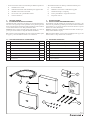 3
3
-
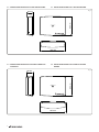 4
4
-
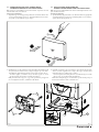 5
5
-
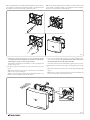 6
6
-
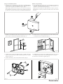 7
7
-
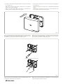 8
8
-
 9
9
-
 10
10
-
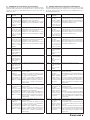 11
11
-
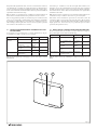 12
12
-
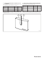 13
13
-
 14
14
-
 15
15
-
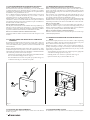 16
16
-
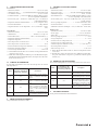 17
17
-
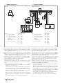 18
18
-
 19
19
-
 20
20


Immergas COD. 3.030908 Istruzioni per l'uso
- Tipo
- Istruzioni per l'uso
in altre lingue
Documenti correlati
Altri documenti
-
Polti Vaporetto MV 10.20 Manuale utente
-
-
Unical ALKON 140 EXT Guida d'installazione
-
 Olimpia Splendid Sherpa Manuale del proprietario
-
 Unical EASYr Manuale utente
-
Ariston GENUS Scheda dati
-
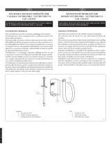 VICTRIX 3.024245 Manuale utente
-
-
 Kalor 20B Manuale utente


