
GENUS
PREMIUM EVO
CALDAIA MURALE ISTANTANEA
A CONDENSAZIONE
WALL-HUNG CONDENSING
GAS BOILER
GENUS PREMIUM EVO
24/30/35
GENUS PREMIUM EVO
SYSTEM 12/18/24/30/35
Istruzioni tecniche per l’istallazione e la manutenzione
Installation and Servicing Instructions
V00

INDICE
Generalità ................................................................................................................ 3
Avvertenze per l’installatore ...............................................................................3
Marcatura CE ............................................................................................................3
Norme di sicurezza ................................................................................................4
Descrizione del prodotto .................................................................................5
Pannello comandi ..................................................................................................5
Dispaly ................................................................................................................6
Vista complessiva ...................................................................................................7
Dimensioni caldaia ................................................................................................8
Distanze minime per l’installazione .................................................................8
Dima Installazione..................................................................................................8
Dati tecnici ................................................................................................................9
Installazione ........................................................................................................13
Avvertenze prima dell’installazione ............................................................. 13
Collegamento gas ............................................................................................... 14
Collegamento idraulico .....................................................................................14
Vista raccordi idraulici ........................................................................................14
Rappresentazione gra ca prevalenza residua circolatore .................... 15
Dispositivo di sovrapressione ......................................................................... 15
Pulizia impianto di riscaldamento ................................................................. 15
Impianti a pavimento.........................................................................................15
Collegamento bollitore .....................................................................................15
Scarico della condensa ......................................................................................16
Schema idraulico ................................................................................................. 17
Collegamento condotti aspirazione e scarico fumi ................................18
Tabella lunghezze condotti aspirazione/scarico ......................................19
Tipologie di aspirazione/scarico Fumi .........................................................20
Collegamenti elettrici ........................................................................................21
Cavo alimentazione ............................................................................................21
C ollegamento periferiche ................................................................................ 22
Collegamento Termostato Ambiente...........................................................22
Schema elettrico ..................................................................................................23
Messa in funzione .............................................................................................24
Procedura di accensione ................................................................................... 24
Predisposizione al servizio ............................................................................... 24
Prima accensione ................................................................................................25
Funzione Disareazione ...................................................................................... 25
Analisi della combustione ................................................................................26
Regolazione della massima potenza riscaldamento .............................. 28
Controllo della potenza di lenta accensione ............................................. 28
Controllo del ritardo di accensione ..............................................................28
Tabella riepilogativa gas ................................................................................... 29
Cambio gas ............................................................................................................ 29
Funzione AUTO.....................................................................................................30
Sistemi di protezione caldaia ......................................................................31
Arresto di sicurezza ............................................................................................. 31
Arresto di blocco ..................................................................................................31
Avviso di malfunzionamento .......................................................................... 32
Tabella riepilogativa codici errore .................................................................33
Funzione antigelo ...............................................................................................34
Area tecnica ......................................................................................................... 35
Manutenzione ....................................................................................................48
Istruzioni per l’apertura della mantellatura
ed ispezione dell’interno ...............................................................................48
Note generali ........................................................................................................49
Pulizia scambiatore primario........................................................................... 49
Prova di funzionamento ...................................................................................49
Operazioni di svuotamento .............................................................................50
Informazioni all’utente ...................................................................................... 50
Targhetta caratteristiche ...................................................................................51
INDEX
Overview ..................................................................................................................3
Advice for the installer ..........................................................................................3
CE labelling ...............................................................................................................3
Safety regulations ..................................................................................................4
Product description ............................................................................................5
Control Panel............................................................................................................5
Display ........................................................................................................................6
Overall wiew .............................................................................................................7
Overall dimension ..................................................................................................8
Minimum clearances ............................................................................................8
Installation Template .............................................................................................8
Technical Information ........................................................................................10
Installation ........................................................................................................... 13
Before installing the appliance .......................................................................13
Gas Connection ....................................................................................................14
Water connection ................................................................................................ 14
View of the boiler connections.......................................................................14
Residual Head of the boiler .............................................................................15
Excessive pressure device ................................................................................15
Cleaning the heating system .......................................................................... 15
Under oor heating ............................................................................................. 15
Tank connection .................................................................................................. 15
Discharge of condensation ..............................................................................16
Water circuit diagram.........................................................................................17
Connecting the ue ............................................................................................18
Table of ue gas exhaust duct lengths ........................................................ 19
Type of air suction/ ue gas exhaust ducting ............................................20
Electrical connection.......................................................................................... 21
Power supply cable ............................................................................................. 21
Peripheral unit connection .............................................................................. 21
Room Thermostat connection ........................................................................ 22
Electrical diagram ................................................................................................ 23
Commissioning ..................................................................................................24
Ignition procedure .............................................................................................. 24
Initial procedures .................................................................................................24
First Ignition .......................................................................................................... 25
Dearation cycle ....................................................................................................25
Combustion checking procedure ..................................................................26
Adjustment the Maximum Heating power ................................................28
Soft Light adjustment ........................................................................................28
Ignition Delay adjustment ...............................................................................28
Table summarising changes ............................................................................ 29
Gas changeover ................................................................................................... 29
AUTO function ...................................................................................................... 30
Boiler protection devices .............................................................................. 31
Safety shut-o ...................................................................................................... 31
Shutdown ...............................................................................................................31
Malfunction warning .........................................................................................32
Table summarising error codes ...................................................................... 33
Anti-freeze function ...........................................................................................34
Technical ares......................................................................................................35
Maintenance ........................................................................................................48
Instruction for opening the casing and performing
an internal inspection .....................................................................................48
General comments .............................................................................................49
Cleaning the primary exchanger ................................................................... 49
Operational test ...................................................................................................49
Draining procedures .......................................................................................... 51
Information for the user .................................................................................... 50
Data Plate Symbol ...............................................................................................51

3
overviewgeneralità
Avvertenze per l’installatore
L’installazione e la prima accensione della caldaia devono essere
e ettuate da personale quali cato in conformità alle normative
nazionali di installazione in vigore e ad eventuali prescrizioni
delle autorità locali e di enti preposti alla salute pubblica.
Dopo l’installazione della caldaia, l’installatore deve consegnare
la dichiarazione di conformità ed il libretto d’uso all’utente nale,
ed informarlo sul funzionamento della caldaia e sui dispositivi di
sicurezza.
Questo apparecchio serve a produrre acqua calda per uso
domestico.
Deve essere allacciato ad un impianto di riscaldamento ed a una rete
di distribuzione di acqua calda sanitaria compatibilmente alle sue
prestazioni ed alla sua potenza.
È vietata l’utilizzazione per scopi diversi da quanto speci cato. Il
costruttore non è considerato responsabile per eventuali danni
derivanti da usi impropri, erronei ed irragionevoli o da un mancato
rispetto delle istruzioni riportate sul presente libretto.
L’installazione, la manutenzione e qualsiasi altro intervento devono
essere e ettuate nel rispetto delle norme vigenti e delle indicazioni
fornite dal costruttore.
Un’errata installazione può causare danni a persone, animali e cose
per i quali l’azienda costruttrice non è responsabile.
La caldaia viene fornita in un imballo di cartone, dopo aver tolto
l’imballo assicurarsi dell’integrità dell’apparecchio e della completezza
della fornitura. In caso di non rispondenza rivolgersi al fornitore.
Gli elementi di imballaggio (gra e, sacchetti in plastica, polistirolo
espanso, ecc.) non devono essere lasciati alla portata dei bambini in
quanto fonti di pericolo.
In caso di guasto e/o cattivo funzionamento spegnere l’apparecchio,
chiudere il rubinetto del gas e non tentare di ripararlo ma rivolgersi a
personale quali cato.
Prima di ogni intervento di manutenzione/riparazione nella caldaia
è necessario togliere l’alimentazione elettrica portando l’interruttore
bipolare esterno alla caldaia in posizione “OFF”.
Eventuali riparazioni, e ettuate utilizzando esclusivamente ricambi
originali, devono essere eseguite solamente da tecnici quali cati. Il
mancato rispetto di quanto sopra può compromettere la sicurezza
dell’apparecchio e fa decadere ogni responsabilità del costruttore.
Nel caso di lavori o manutenzioni di strutture poste nelle vicinanze dei
condotti o dei dispositivi di scarico dei fumi e loro accessori, mettere
fuori servizio l’apparecchio portando l’interruttore esterno bipolare
in posizione OFF e chiudendo il rubinetto del gas.
A lavori ultimati far veri care l’e cienza dei condotti e dei dispositivi
da personale tecnico quali cato.
Per la pulizia delle parti esterne spegnere la caldaia e portare
l’interruttore esterno in posizione “OFF”.
E ettuare la pulizia con un panno umido imbevuto di acqua
saponata.
Non utilizzare detersivi aggressivi, insetticidi o prodotti tossici. Il
rispetto delle norme vigenti permette un funzionamento sicuro,
ecologico e a risparmio energetico.
Nel caso di uso di kit od optional si dovranno utilizzare solo quelli
originali.
Conforme al DM 174 del 06-04-2004 in attuazione della Direttiva
Europea 98/83 CE relativa alla qualità delle acque
Marcatura CE
Il marchio CE garantisce la rispondenza dell’apparecchio alle seguenti
direttive:
- 2009/142/CEE - relativa agli apparecchi a gas
- 2004/108/EC - relativa alla compatibilità elettromagnetica
- 92/42/CEE - relativa al rendimento energetico
- 2006/95/EC - relativa alla sicurezza elettrica
Advice for the installer
The installation and rst ignition of the boiler must be performed
by quali ed personnel in compliance with current national
regulations regarding installation, and in conformity with any
requirements established by local authorities and public health
organisations.
After the boiler has been installed, the installer must ensure
that the end user receives the declaration of conformity and the
operating manual, and should provide all necessary information
as to how the boiler and the safety devices should be handled.
This appliance is designed to produce hot water for domestic use.
It should be connected to a heating system and a distribution
network for domestic hot water, both of which must be compatible
with its performance and power levels.
The use of the appliance for purposes other than those speci ed is
strictly forbidden. The manufacturer cannot be held responsible for
any damage caused by improper, incorrect and unreasonable use of
the appliance or by the failure to comply with the instructions given
in this manual.
Installation, maintenance and all other interventions must be carried
out in full conformity with the governing legal regulations and the
instructions provided by the manufacturer. Incorrect installation can
harm persons, animals and possessions; the manufacturing company
shall not be held responsible for any damage caused as a result.
The boiler is delivered in a carton. Once you have removed all the
packaging, make sure the appliance is intact and that no parts are
missing. If this is not the case, please contact your supplier.
Keep all packaging material (clips, plastic bags, polystyrene foam, etc.) out
of reach of children as it may present a potential hazard.
In the event of a fault and/or malfunction, turn the appliance o , turn
o the gas cock and do not attempt to repair it yourself. Contact a
quali ed professional instead.
Before any maintenance or repair work is performed on the boiler,
make sure you have disconnected it from the electricity supply by
switching the external bipolar switch to the “OFF” position and
removing the fuse.
All repairs, which should only be performed using original spare parts,
should be carried out by a quali ed professional. Failure to comply
with the above instructions could compromise the safety of the
appliance and invalidate all liability on the part of the manufacturer.
In the event of any maintenance or other structural work in the
immediate vicinity of the ducts or ue gas exhaust devices and
their accessories, switch the appliance o by switching the external
bipolar switch to the “OFF” position and shutting o the gas control
valve. When the work has been completed, ask a quali ed technician
to check the e ciency of the ducting and the devices.
Turn the boiler o and turn the external switch “OFF” to clean the
exterior parts of the appliance.
Clean using a cloth dampened with soapy water. Do not use
aggressive detergents, insecticides or toxic products. If the appliance
is used in full compliance with current legislation, it will operate in a
safe, environmentally-friendly and cost-e cient manner.
If using kits or optional extras, make sure they are authentic.
CE labelling
The CE mark guarantees that the appliance conforms to the follow-
ing directives:
- 2009/142/CEE relating to gas appliances
- 2004/108/CEE relating to electromagnetic compatibility
- 92/42/CEE relating to energy e ciency
- 2006/95/CEE relating to electrical safety

4
generalità overview
Norme di sicurezza
Legenda simboli:
Il mancato rispetto dell’avvertenza comporta rischio di lesioni, in
determinate circostanze anche mortali, per le persone
Il mancato rispetto dell’avvertenza comporta rischio di
danneggiamenti, in determinate circostanze anche gravi, per
oggetti, piante o animali
Installare l’apparecchio su parete solida, non soggetta a vibrazioni.
Rumorosità durante il funzionamento.
Non danneggiare, nel forare la parete, cavi elettrici o tubazioni preesistenti.
Folgorazione per contatto con conduttori sotto tensione. Esplosioni, incendi o
intossicazioni per perdita gas dalle tubazioni danneggiate. Danneggiamento
impianti preesistenti. Allagamenti per perdita acqua dalle tubazioni danneggiate.
Eseguire i collegamenti elettrici con conduttori di sezione adeguata.
Incendio per surriscaldamento dovuto al passaggio di corrente elettrica in cavi
sottodimensionati.
Proteggere tubi e cavi di collegamento in modo da evitare il loro
danneggiamento.
Folgorazione per contatto con conduttori sotto tensione. Esplosioni, incendi o
intossicazioni per perdita gas dalle tubazioni danneggiate. Allagamenti per perdita
acqua dalle tubazioni danneggiate.
Assicurarsi che l’ambiente di installazione e gli impianti a cui deve connettersi
l’apparecchiatura siano conformi alle normative vigenti.
Folgorazione per contatto con conduttori sotto tensione incorrettamente installati.
Danneggiamento dell’apparecchio per condizioni di funzionamento improprie.
Adoperare utensili ed attrezzature manuali adeguati all’uso (in particolare
assicurarsi che l’utensile non sia deteriorato e che il manico sia integro e
correttamente ssato), utilizzarli correttamente, assicurarli da eventuale
caduta dall’alto, riporli dopo l’uso.
Lesioni personali per proiezione di schegge o frammenti, inalazione polveri, urti,
tagli, punture, abrasioni. Danneggiamento dell’apparecchio o di oggetti circostanti
per proiezione di schegge, colpi, incisioni.
Adoperare attrezzature elettriche adeguate all’uso (in particolare assicurarsi
che il cavo e la spina di alimentazione siano integri e che le parti dotate di moto
rotativo o alternativo siano correttamente ssate), utilizzarle correttamente,
non intralciare i passaggi con il cavo di alimentazione, assicurarle da eventuale
caduta dall’alto, scollegare e riporle dopo l’uso.
Lesioni personali per proiezione di schegge o frammenti, inalazione polveri, urti,
tagli, punture, abrasioni, rumore, vibrazioni. Danneggiamento dell’apparecchio o di
oggetti circostanti per proiezione di schegge, colpi, incisioni.
Assicurarsi che le scale portatili siano stabilmente appoggiate, che siano
appropriatamente resistenti, che i gradini siano integri e non scivolosi, che
non vengano spostate con qualcuno sopra, che qualcuno vigili.
Lesioni personali per la caduta dall’alto o per cesoiamento (scale doppie).
Assicurarsi che le scale a castello siano stabilmente appoggiate, che siano
appropriatamente resistenti, che i gradini siano integri e non scivolosi, che
abbiano mancorrenti lungo la rampa e parapetti sul pianerottolo.
Lesioni personali per la caduta dall’alto.
Assicurarsi, durante i lavori eseguiti in quota (in genere con dislivello superiore
a due metri), che siano adottati parapetti perimetrali nella zona di lavoro
o imbragature individuali atti a prevenire la caduta, che lo spazio percorso
durante l’eventuale caduta sia libero da ostacoli pericolosi, che l’eventuale
impatto sia attutito da super ci di arresto semirigide o deformabili.
Lesioni personali per la caduta dall’alto.
Assicurarsi che il luogo di lavoro abbia adeguate condizioni igienico sanitarie
in riferimento all’illuminazione, all’aerazione, alla solidità.
Lesioni personali per urti, inciampi, ecc.
Proteggere con adeguato materiale l’apparecchio e le aree in prossimità del
luogo di lavoro.
Danneggiamento dell’apparecchio o di oggetti circostanti per proiezione di
schegge, colpi, incisioni.
Movimentare l’apparecchio con le dovute protezioni e con la dovuta cautela.
Danneggiamento dell’apparecchio o di oggetti circostanti per urti, colpi, incisioni,
schiacciamento.
Indossare, durante le lavorazioni, gli indumenti e gli equipaggiamenti
protettivi individuali.
Lesioni personali per folgorazione, proiezione di schegge o frammenti, inalazioni
polveri, urti, tagli, punture, abrasioni, rumore, vibrazioni.
Organizzare la dislocazione del materiale e delle attrezzature in modo da
rendere agevole e sicura la movimentazione, evitando cataste che possano
essere soggette a cedimenti o crolli.
Danneggiamento dell’apparecchio o di oggetti circostanti per urti, colpi, incisioni,
schiacciamento.
Le operazioni all’interno dell’apparecchio devono essere eseguite con la
cautela necessaria ad evitare bruschi contatti con parti acuminate.
Lesioni personali per tagli, punture, abrasioni.
Ripristinare tutte le funzioni di sicurezza e controllo interessate da un
intervento sull’apparecchio ed accertarne la funzionalità prima della rimessa
in servizio.
Esplosioni, incendi o intossicazioni per perdita gas o per incorretto scarico fumi.
Danneggiamento o blocco dell’apparecchio per funzionamento fuori controllo.
Svuotare i componenti che potrebbero contenere acqua calda, attivando
eventuali s ati, prima della loro manipolazione.
Lesioni personali per ustioni.
E ettuare la disincrostazione da calcare di componenti attenendosi a quanto
speci cato nella scheda di sicurezza del prodotto usato, aerando l’ambiente,
indossando indumenti protettivi, evitando miscelazioni di prodotti diversi,
proteggendo l’apparecchio e gli oggetti circostanti.
Lesioni personali per contatto di pelle o occhi con sostanze acide, inalazione o
ingestione di agenti chimici nocivi. Danneggiamento dell’apparecchio o di oggetti
circostanti per corrosione da sostanze acide.
Nel caso si avverta odore di bruciato o si veda del fumo fuoriuscire
dall’apparecchio, togliere l’alimentazione elettrica, aprire le nestre ed
avvisare il tecnico.
Lesioni personali per ustioni, inalazione fumi, intossicazione.
Safety regulations
Key to symbols:
Failure to comply with this warning implies the risk of personal
injury, in some circumstances even fatal
Failure to comply with this warning implies the risk of damage, in
some circumstances even serious, to property, plants or animals.
I
nstall the appliance on a solid wall which is not subject to vibration.
Noisiness during operation.
When drilling holes in the wall for installation purposes, take care not to damage
any electrical wiring or existing piping.
Electrocution caused by contact with live wires. Explosions, res or asphyxiation caused
by gas leaking from damaged piping. Damage to existing installations. Flooding caused
by water leaking from damaged piping.
Perform all electrical connections using wires which have a suitable section.
Fire caused by overheating due to electrical current passing through undersized cables.
Protect all connection pipes and wires in order to prevent them from being
damaged.
Electrocution caused by contact with live wires. Explosions, res or asphyxiation caused
by gas leaking from damaged piping. Flooding caused by water leaking from damaged
piping.
Make sure the installation site and any systems to which the appliance must be
connected comply with the applicable norms in force.
Electrocution caused by contact with live wires which have been installed incorrectly.
Damage to the appliance caused by improper operating conditions.
Use suitable manual tools and equipment (make sure in particular that the tool is
not worn out and that its handle is xed properly); use them correctly and make
sure they do not fall from a height. Replace them once you have nished using
them.
Personal injury from the falling splinters or fragments, inhalation of dust, shocks, cuts,
pricks and abrasions. Damage to the appliance or surrounding objects caused by falling
splinters, knocks and incisions.
Use electrical equipment suitable for its intended use (in particular, make sure
that the power supply cable and plug are intact and that the parts featuring rotary
or reciprocating motions are fastened correctly); use this equipment correctly; do
not obstruct passageways with the power supply cable, make sure no equipment
could fall from a height. Disconnect it and replace it safely after use.
Personal injury caused by falling splinters or fragments, inhalation of dust, knocks,
cuts, puncture wounds, abrasions, noise and vibration. Damage to the appliance or
surrounding objects caused by falling splinters, knocks and incisions.
Make sure any portable ladders are positioned securely, that they are suitably
strong and that the steps are intact and not slippery and do not wobble when
someone climbs them. Ensure someone provides supervision at all times.
Personal injury caused by falling from a height or cuts (stepladders shutting
accidentally).
Make sure any rolling ladders are positioned securely, that they are suitably
strong, that the steps are intact and not slippery and that the ladders are tted
with handrails on either side of the ladder and parapets on the landing.
Personal injury caused by falling from a height.
During all work carried out at a certain height (generally with a di erence in
height of more than two metres), make sure that parapets are used to surround
the work area or that individual harnesses are used to prevent falls. The space
where any accidental fall may occur should be free from dangerous obstacles,
and any impact upon falling should be cushioned by semi-rigid or deformable
surfaces.
Personal injury caused by falling from a height.
Make sure the workplace has suitable hygiene and sanitary conditions in terms of
lighting, ventilation and solidity of the structures.
Personal injury caused by knocks, stumbling etc.
Protect the appliance and all areas in the vicinity of the work place using suitable
material.
Damage to the appliance or surrounding objects caused by falling splinters, knocks
and incisions.
Handle the appliance with suitable protection and with care.
Damage to the appliance or surrounding objects from shocks, knocks, incisions and
squashing.
During all work procedures, wear individual protective clothing and equipment.
Personal injury caused by electrocution, falling splinters or fragments, inhalation of
dust, shocks, cuts, puncture wounds, abrasions, noise and vibration.
Place all debris and equipment in such a way as to make movement easy and safe,
avoiding the formation of any piles which could yield or collapse.
Damage to the appliance or surrounding objects from shocks, knocks, incisions and
squashing.
All operations inside the appliance must be performed with the necessary caution
in order to avoid abrupt contact with sharp parts.
Personal injury caused by cuts, puncture wounds and abrasions.
Reset all the safety and control functions a ected by any work performed on the
appliance and make sure they operate correctly before restarting the appliance.
Explosions, res or asphyxiation caused by gas leaks or an incorrect ue gas exhaust.
Damage or shutdown of the appliance caused by out-of-control operation.
Before handling, empty all components that may contain hot water, carrying out
any bleeding if necessary.
Personal injury caused by burns.
Descale the components, in accordance with the instructions provided on the
safety data sheet of the product used, airing the room, wearing protective
clothing, avoid mixing di erent products, and protect the appliance and
surrounding objects.
Personal injury caused by acidic substances coming into contact with skin or eyes;
inhaling or swallowing harmful chemical agents. Damage to the appliance or
surrounding objects due to corrosion caused by acidic substances.
If you detect a smell of burning or smoke, keep clear of the appliance, disconnect
it from the electricity supply, open all windows and contact the technician.
Personal injury caused by burns, smoke inhalation, asphyxiation.

5
descrizione del prodotto product description
Pannello comandi
24/01/2011 12:25
44°C 40°C
1
2
3
6
5
4
7
12
10
11
9
8
Control Panel
Legenda:
1. Display
2. Tasti +/- regolazione temperatura acqua sanitaria
3. Tasto ON/OFF
4. Idrometro
5. Led blu - segnalazione presenza amma
6. Tasto ESC (Back)
7. “Encoder” programmazione
8. Tasto OK
9. Tasto Mode
Selezione modalità di funzionamento caldaia)
10. Tasto RESET
11. Tasto AUTO (Attivazione Termoregolazione)
12. Tasti +/- regolazione temperatura riscaldamento
Legenda:
1. Display
2. Domestic Hot Water adjustment button +/-
3. ON/OFF button
4. Pressure gauge
5. Flame detected Blue LED
6. Esc button (Back)
7. “encoder” programming knob
8. Ok button programming key
9. MODE button
(Operation mode selection summer/winter)
10. RESET button
11. Auto button (To activate Thermoregulation)
12. Heating temperature adjustument button +/-

6
descrizione del prodotto product description
Display
Caldaia base - Boiler base
Caldaia completa - Boiler complete
Display
01/01/2000 00:00
40°C 70°C
Modalità riscaldamento
Temperatura impostata
XX °C
Heating operation set
C.H. set temperature
Modalità riscaldamento attivo
Temperatura di mandata impianto
XX °C
Heating operation active
C.H. send temperature
Modalità sanitario
Temperatura impostata
XX °C
Modalità sanitario
D.H.W. set temperature
Modalità sanitario attivo
Temperatura impostata
XX °C
Modalità sanitario attivo
D.H.W. temperature
Temperatura esterna
(attivo con sonda esterna collegata - option)
XX °C
External temperature (°C)
(only with external sensor connected)
Segnalazione errori
con indicazione codice e descrizione
ALERT
Error code signals
The display show the code and description
Funzione AUTO attivata
auto
AUTO function activated
Funzione Comfort attivata COMFORT Hot Water Comfort activated
Sonda solare collegata (optional) Solar temperature probe connected (optional)
Segnalazione presenza amma con indicazione
potenza utilizzata
(modalità display - caldaia completa)
Flame detected with indication of power used or
indication
(set display - boiler complete)
Pressione impianto - bar
(modalità display - caldaia completa)
1.3 bar
Digital pressure gauge
(set display - boiler complete)
Testo descrittivo
(modalità display - caldaia completa)
Riscaldamento
Central Heating
Scrolling text displaying operation as information
(set display - boiler complete)
40°C
70°C
0,7 bar
Stand-by

7
descrizione del prodotto product description
Vista complessiva Overall view
Legenda
1. Collettore scarico fumi
2. Valvola sfogo aria
3. Scambiatore primario
4. Elettrodo di rilevazione amma
5. Sonda ritorno riscaldamento
6. Sonda mandata riscaldamento
7. Silenziatore
Verde - GENUS PREMIUM EVO SYSTEM 18
Nero - GENUS PREMIUM EVO /SYSTEM 24/30/35
8. Scambiatore sanitario
9. Valvola gas
10. Sifone
12. Valvola di sicurezza 3 bar
13. Rubinetto di riempimento
14. Filtro circuito riscaldamento
15. Circolatore modulante con desareatore
16. Flussimetro sanitario
17. Valvola deviatrice motorizzata
18. Sensore di pressione
19. Ventilatore modulante
20. Elettrodo di accensione
21. Accenditore
22. Termofusibile
23. Prese analisi fumi
Legend:
1. Flue connector
2. Manual air vent
3. Main heat exchanger
4. Detection electrode
5. C.H. return temperature probe
6. C.H. Flow temperature probe
7. Silencer
Green - GENUS PREMIUM EVO SYSTEM 18
Black - GENUS PREMIUM EVO /SYSTEM 24/30/35
8. Secondary heat exchanger
9. Gas valve
10. Condensate trap
12. C.H. pressure relief valve
13. Filling valve
14. C.H. circuit lter
15. Circulation Pump (Modulating) with air release valve
16. D.H.W. ow switch
17. Diverter valve
18. Water pressure sensor
19. Modulating fan
20. Ignition electrodes
21. Ignitor
22. Thermal fuse
23. Combustion analysis test point
1
2
3
4
5
6
7
9
10
12
14
15
16
17
18
19
20
21
22
23
8
13
1
2
3
4
5
6
7
9
10
12
14
15
18
13
17
19
20
21
22
23
GENUS PREMIUM EVO
GENUS PREMIUM EVO SYSTEM

8
descrizione del prodotto product description
Dimensioni caldaia
Distanze minime per l’installazione
Per permettere un agevole svolgimento delle operazioni di
manutenzione della caldaia è necessario rispettare un’adeguata
distanza nell’installazione.
Posizionare la caldaia secondo le regole della buona tecnica
utilizzando una livella a bolla.
450
053
0 0 3
50 50
420020021002
30
60
320
Dima Installazione Template
A. Mandata impianto
B. Uscita acqua calda
C. Ingresso Gas
D. Entrata acqua fredda
E. Ritorno Impianto
R. Ritorno bollitore
28
770
200
150
***
120 120
200
180
65 65 67 67
25 770
28
770
200
120 120
200
65 6567 67
R
*** = 315 - mod. 24
385 - mod. 30-35
GENUS PREMIUM EVO
GENUS PREMIUM EVO SYSTEM
Overall Dimensions
A. Central Heating Flow
B. Domestic Hot Water Outlet
C. Gas Inlet
D. Domestic Cold Water Inlet
E. Central Heating Return
R. Tank Return
Minimum clearances
In order to allow easy access to the boiler for maintenance operations,
The boiler must be installed in accordance with the clearances stated
below.
*** = 315 - mod. ù18-24
385 - mod. 30-35

9
descrizione del prodotto product description
Dati tecnici
NOTE GEN.
Modello: GENUS PREMIUM EVO 24 30 35
Certi cazione CE (pin) 0085CL0440
Tipo caldaia
C13(X)-C23-C33(X)-C43(X)-C53(X)-C63(X)C83(X)-C93(X)
B23-B23P-B33
PRESTAZIONI ENERGETICHE
Portata termica nominale in riscaldamento max/min (Hi) Qn kW 22/2,5 28,0/3,0 31/3,5
Portata termica nominale in riscaldamento max/min (Hs) Qn kW 24,4/2,8 31,1/3,3 34,4/3,9
Portata termica nominale in sanitario max/min (Hi) Qn kW 26/2,5 30,0/3,0 34,5/3,5
Portata termica nominale in sanitario max/min (Hs) Qn kW 28,9/2,8 33,3/3,3 38,3/3,9
Potenza termica riscaldamento max/min (80°C-60°C) Pn kW 21,5/2,4 27,4/2,9 30,3/3,4
Potenza termica max/min (50°C-30°C) Pn kW 23,4/2,6 29,7/3,1 33/3,6
Potenza termica max/min sanitario Pn kW 25,4/2,4 29,3/2,9 33,7/3,4
Rendimento di combustione (ai fumi) % 98,0 98,0 97,9
Rendimento alla portata termica nominale (60/80°C) Hi/Hs % 97,8/88
97,7/88
97,7/88
Rendimento alla portata termica nominale (30/50°C) Hi/Hs %
106,2/95,7
106,2/95,6
106,5/95,9
Rendimento al 30 % a 30°C (condensation) Hi/Hs %
108,1/97,3
108/97,3 108/97,3
Rendimento al 30 % a 47°C Hi/Hs % 97,8/88,1 97,8/88,1 97,8/88,1
Rendimento al minimo (60/80°C) Hi/Hs % 97,8/88,1 97,8/88 97,7/88
Stelle di rendimento (dir. 92/42/EEC) stars **** **** ****
Rating Sedbuk class A/90,1 A/90,1 A/90,1
Massima perdita di calore al mantello (ΔT = 50°C) %
Perdite al camino bruciatore funzionante % 1,9 2,0 2,0
EMISSIONI
Prevalenza residua di evacuazione Pa 100 90 100
Classe Nox class 5 5 5
Temperatura fumi (G20) (80°C-60°C) °C 62 62 63
Contenuto di CO
2
(G20) (80°C-60°C) % 9,3 9,3 9,3
Contenuto di CO (0%O2) (80°C-60°C) ppm 143 134 99
Contenuto di O
2
(G20) (80°C-60°C) % 4,0 4,0 4,0
Portata massima fumi (G20) (80°C-60°C) Kg/h 41,6 48,0 55,2
Eccesso d’aria (80°C-60°C) % 23 23 23
CIRCUITO RISCLDAMENTO
Pressione di precarica vaso di espansione bar 1 1 1
Pressione massima di riscaldamento
bar 3 3 3
Capacità vaso di espansione l 8 8 8
Temperatura di riscaldamento min/max (range alte temperature) °C 35/ 82 35/ 82 35/ 82
Temperatura di riscaldamento min/max (range basse temperature) °C 20/ 45 20/ 45 20/ 45
CIRCUITO SANITARIO
Temperatura sanitario min/max °C 36/60 36/60 36/60
Portata speci ca in sanitario (10 min. con ΔT=30°C) l/min
12,2 14,1 16,0
Quantità istantanea di acqua calda ΔT=25°C l/min 14,6 16,8 19,3
Quantità istantanea di acqua calda ΔT=35°C l/min 10,4 12,0 13,8
Stelle comfort sanitario (EN13203) stars *** *** ***
Prelievo minimo di acqua calda l/min <2 <2 <2
Pressione acqua sanitaria max/min bar 7/0,3 7/0,3 7/0,3
DATI ELETTR. AMB.
Tensione/frequanza di alimentazione V/Hz 230 / 50 230 / 50 230 / 50
Potenza elettrica assorbita totale W 78 83 83
Temperatura ambiente minima di utilizzo °C 5 5 5
Gradi di protezione impianto elettrico IP X5D X5D X5D
Peso kg 35 35 36
La pagina si sta caricando...

11
descrizione del prodotto product description
Dati tecnici
NOTE GEN.
Modello: GENUS PREMIUM EVO SYSTEM 12 18 24 30 35
Certi cazione CE (pin) 0085CL0440
Tipo caldaia
C13(X)-C23-C33(X)-C43(X)-C53(X)-C63(X)C83(X)-C93(X) B23-
B23P-B33
PRESTAZIONI ENERGETICHE
Portata termica nominale in riscaldamento max/min (Hi) Qn kW 12,0/3,0 18,0/4,5 22,0/2,5 28,0/3,0 31,0/3,5
Portata termica nominale in riscaldamento max/min (Hs) Qn kW 13,3/3,3 20,0/5,0 24,4/2,8 31,1/3,3 34,4/3,9
Portata termica nominale in sanitario max/min (Hi) Qn kW 12,0/3,0 18,0/4,5 26,0/2,5 30,0/3,0 34,5/3,5
Portata termica nominale in sanitario max/min (Hs) Qn kW 13,3/3,3 20,0/5,0 28,9/2,8 33,3/3,3 38,3/3,9
Potenza termica riscaldamento max/min (80°C-60°C) Pn kW 11,7/2,9 17,6/4,4 21,5/2,4 27,4/2,9 30,3/3,4
Potenza termica max/min (50°C-30°C) Pn kW 12,8/3,2 19,1/4,7 23,4/2,6 29,7/3,1 33,0/3,6
Potenza termica max/min sanitario Pn kW 11,7/2,9 17,6/4,4 25,4/2,4 29,3/2,9 33,7/3,4
Rendimento di combustione (ai fumi) % 98,2 98,0 98,0 98,0 97,9
Rendimento alla portata termica nominale (60/80°C) Hi/Hs % 97,6/87,9 97,6/87,9 97,8/88
97,7/88
97,7/88
Rendimento alla portata termica nominale (30/50°C) Hi/Hs % 106,6/96 106,1/95,5
106,2/95,7
106,2/95,6 106,5/95,9
Rendimento al 30 % a 30°C (condensation) Hi/Hs % 107,7/97 107,7/97
108,1/97,3
108/97,3 108/97,3
Rendimento al 30 % a 47°C Hi/Hs % 97,7/88 97,7/88
97,8/88,1
97,8/88,1 97,8/88,1
Rendimento al minimo (60/80°C) Hi/Hs % 97,5/87,8 97,6/87,9
97,8/88,1
97,8/88 97,7/88
Stelle di rendimento (dir. 92/42/EEC) stars **** **** **** **** ****
Rating Sedbuk class A/90,1 A/90,1 A/90,1 A/90,1 A/90,1
Massima perdita di calore al mantello (ΔT = 50°C) %
Perdite al camino bruciatore funzionante % 2,0 2,0 1,9 2,0 2,0
EMISSIONI
Prevalenza residua di evacuazione Pa 100 100 100 90 100
Classe Nox class 55555
Temperatura fumi (G20) (80°C-60°C) °C 57 61 62 62 63
Contenuto di CO
2
(G20) (80°C-60°C) % 9,0 9,0 9,3 9,3 9,3
Contenuto di CO (0%O2) (80°C-60°C) ppm 37 93 143 134 99
Contenuto di O
2
(G20) (80°C-60°C) % 4,5 4,5 4,0 4,0 4,0
Portata massima fumi (G20) (80°C-60°C) Kg/h 19,8 29,7 41,6 48,0 55,2
Eccesso d’aria (80°C-60°C) % 27 27 23 23 23
CIRCUITO RISCLDAMENTO
Pressione di precarica vaso di espansione bar 11111
Pressione massima di riscaldamento bar 33333
Capacità vaso di espansione l 88888
Temperatura di riscaldamento min/max
(ran
g
e alte tem
p
erature)
°C 35/ 82 35/ 82 35/ 82 35/ 82 35/ 82
Temperatura di riscaldamento min/max
(ran
g
e basse tem
p
erature)
°C 20/ 45 20/ 45 20/ 45 20/ 45 20/ 45
CIRCUITO SANITARIO
Temperatura sanitario min/max °C 40/60 40/60 40/60 40/60 40/60
DATI ELETTR. AMB.
Tensione/frequanza di alimentazione V/Hz 230 / 50 230 / 50 230 / 50 230 / 50 230 / 50
Potenza elettrica assorbita totale W 80 80 78 83 82
Temperatura ambiente minima di utilizzo °C 55555
Gradi di protezione impianto elettrico IP X5D X5D X5D X5D X5D
Peso kg 32 35 35 35 36
La pagina si sta caricando...

13
installationinstallazione
Avvertenze prima dell’installazione
La caldaia serve a riscaldare l’acqua ad una temperatura inferiore a
quella di ebollizione.
Essa deve essere allacciata ad un impianto di riscaldamento e ad
una rete di acqua sanitaria entrambi dimensionati in base alle sue
prestazione ed alla sua potenza.
Prima di collegare la caldaia è necessario:
- e ettuare un lavaggio accurato delle tubazioni degli impianti per
rimuovere eventuali residui di lettature, saldature o sporcizie che
possano compromettere il corretto funzionamento della caldaia;
- veri care la predisposizione della caldaia per il funzionamento con
il tipo di gas disponibile (leggere quanto riportato sull’etichetta
dell’imballo e sulla targhetta caratteristiche della caldaia);
- controllare che la canna fumaria non presenti strozzature e non vi
siano collegati scarichi di altri apparecchi, salvo che questa sia stata
realizzata per servire più utenze secondo quanto previsto dalle
Norme vigenti;
- controllare che, nel caso di raccordo su canne fumarie preesistenti,
queste siano state perfettamente pulite e non presentino scorie,
in quanto l’eventuale distacco delle stesse potrebbe ostruire il
passaggio dei fumi, causando situazioni di pericolo;
- controllare che, nel caso di raccordo su canne fumarie non idonee,
queste siano state intubate;
- in presenza di acque con durezza particolarmente elevata, si avrà
rischio di accumulo di calcare con conseguente diminuzione di
e cienza dei componenti della caldaia.
- evitare l’installazione dell’apparecchio in zone dove l’aria di
combustione contiene un elevato tasso di cloro (ambienti come una
piscina), e/o di altri prodotti nocivi come ad esempio l’ammoniaca
(negozi di parrucchiera), gli agenti alcalini (lavanderie)...
- Il tasso di zolfo del gas utilizzato deve essere inferiore alle vigenti
normative europee: punta massima nell’anno per breve periodo:
150 mg/m
3
di gas e media nell’anno di 30 mg/m
3
di gas.
Gli apparecchi tipo C, la cui camera di combustione e circuito di
alimentazione d’aria sono a tenuta stagna rispetto all’ambiente, non
hanno alcuna limitazione dovuta alle condizioni di aerazione ed al
volume del locale.
Per non compromettere il regolare funzionamento della caldaia il
luogo di installazione deve essere idoneo in relazione al valore della
temperatura limite di funzionamento ed essere protetto in modo
tale che la caldaia non entri direttamente in contatto con gli agenti
atmosferici.
La caldaia è progettata per l’installazione a parete e deve deve essere
installata su una parete idonea a sostenerne il peso.
Nella creazione di un vano tecnico si impone il rispetto di distanze
minime che garantiscano l’accessibilità alle parti della caldaia.
ATTENZIONE!
Nessun oggetto in ammabile deve trovarsi nelle
vicinanze della caldaia.
Assicurarsi che l’ambiente di installazione e gli impianti
a cui deve connettersi l’apparecchio siano conformi alle
normative vigenti.
Se nel locale di installazione sono presenti polveri
e/o vapori aggressivi, l’apparecchio deve funzionare
indipendentemente dall’aria del locale.
ATTENZIONE!
L’installazione, la prima accensione, la manutenzione
e la riparazione della caldaia, devono essere e ettuate
da personale quali cato in conformità alle normative
nazionali di installazione in vigore e ad eventuali
prescrizioni delle autorità locali e di enti preposti alla
salute pubblica.
Before installing the appliance
The boiler heats water to a temperature below boiling.
It should be connected to a heating system and to a domestic
water mains supply, both of which must correspond in size to the
performance and its power of the appliance.
Before connecting the boiler, it is rst necessary to perform the
following operations:
- Carefully wash the system piping in order to remove any screw
thread or welding residues, or any dirt which might prevent the
boiler from operating correctly.
- Make sure that the boiler is set up for operation with the type of
gas available (read the information on the packaging label and on
the boiler data plate).
- Make sure that there are no obstacles inside ue exhaust and that
it does not contain any discharge from other appliances, unless
the ue is meant to serve more than one user (in accordance with
current legal requirements).
- Where there is already a connection to existing ue exhausts,
check that these exhausts have been perfectly cleaned and are
without residues, because any disconnection could obstruct the
passage of fumes and create potentially dangerous situations.
- Make sure that, where unsuitable ue exhausts are attached, they
have been ducted.
- In areas with particularly hard water, limescale may build up on the
components inside the boiler and reduce its overall e ciency
-
The sulphur levels in the gas used should be below current
accepted European standards: maximum in one year over a short
period of time: 150 mg/m3 of gas and an average over the year of
30 mg/m3 of gas.
C-type boilers, with combustion chambers and air supply circuits
which are completely sealed from the air outside, do not have any
limitations concerning the ventilation and size of the room in which
they are installed.
So that the normal operation of the boiler is not compromised,
the place in which it is installed must be suitable with regard to
the operating limit temperature value and the appliance should
be protected so that it does not come into direct contact with
atmospheric agents.
The boiler must be installed on a solid, non-combustible, permanent
wall to prevent access from the rear.
When creating a space for the boiler, the minimum distances (which
ensure that various parts of the boiler may be accessed after it has
been installed) should be respected.
WARNING
No in ammable items should be left in the vicinity of the
boiler.
Make sure the installation site and any systems to which
the appliance must be connected are fully compliant
with the current applicable legislation.
If dust and/or aggressive vapours are present in the room
in which it is to be installed, the appliance must operate
independently of the air inside the room.
WARNING
The installation and rst ignition of the boiler must be
performed by quali ed personnel in compliance with
current national regulations regarding installation, and
in conformity with any requirements established by local
authorities and public health organisations.

14
installazione installation
Collegamento idraulico
In gura sono rappresentati i raccordi per l’allacciamento idraulico e
gas della caldaia.
Veri care che la pressione massima della rete idrica non superi i 6
bar; in caso contrario è necessario installare un riduttore di pressione.
Vista raccordi idraulici View of the Boiler Connections
GENUS PREMIUM EVO
GENUS PREMIUM EVO SYSTEM
A
B
C
D
E
I
G
H
F
Legenda:
A. Mandata Impianto
B. Uscita acqua calda - GENUS PREMIUM EVO
C. Ingresso Gas
D. Entrata acqua fredda
E. Ritorno impianto
F. Scarico dispositivo di sovrapressione
G. Rubinetto di riempiemento
H. Rubinetto di svuotamento
R. Ritorno bollitore - GENUS PREMIUM EVO SYSTEM
A
R
C
D
E
I
G
H
F
Collegamento gas
La caldaia è stata progettata per utilizzare gas appartenenti alle
categorie come riportato sulla seguente tabella
NAZIONE MODELLO CATEGORIE
IT
GENUS PREMIUM EVO 24/30/35
GENUS PREMIUM EVO SYSTEM 12/18/24/30/35
II
2H3P
Accertarsi tramite le targhette poste sull’imballo e sull’apparecchio
che la caldaia sia destinata al paese in cui dovrà essere installata, che
la categoria gas per la quale la caldaia è stata progettata corrisponda
ad una delle categorie ammesse dal paese di destinazione.
La tubazione di adduzione del gas deve essere realizzata e
dimensionata secondo quanto prescritto dalle Norme speci che
ed in base alla potenza massima della caldaia, assicurarsi anche
del corretto dimensionamento ed allacciamento del rubinetto di
intercettazione.
Prima dell’installazione si consiglia un’accurata pulizia delle
tubazioni del gas per rimuovere eventuali residui che potrebbero
compromettere il funzionamento della caldaia.
E’ necessario veri care che il gas distribuito corrisponda a quello per
cui è stata predisposta la caldaia (vedi targa dati posta in caldaia).
E’ inoltre importante veri care la pressione del gas (metano o GPL)
che si andrà ad utilizzare per l’alimentazione della caldaia, in quanto
se insu ciente può ridurre la potenza del generatore con disagi per
l’utente.
Gas connection
The boiler was designed to use gases belonging to the categories as
shown in the following table.
COUNTRY MODEL CATEGORIES
GENUS PREMIUM EVO 24/30/35
GENUS PREMIUM EVO SYSTEM 12/18/24/30/35
Make sure, using the labels on the packaging and the data plate on
the appliance itself, that the boiler is in the correct country and that
the gas category for which the boiler was designed corresponds to
one of the categories available in the country where it will be used.
The gas supply piping must be created and measured out in
compliance with speci c legal requirements and in accordance with
the maximum power of the boiler; you should also make sure that
the shut-o valve is the right size and that it is connected correctly.
Before carrying out the installation, it is recommended that the fuel
pipes are cleaned thoroughly in order to remove any residues which
could prevent the boiler from operating correctly.
Check that the supplied gas corresponds to the type of gas for which
the boiler was designed (see the data plate located on the appliance
itself).
It is also important to check that the pressure of the gas (methane
or LPG) you will be using to feed the boiler is suitable, because if it
is insu cient the power of the generator may be reduced, causing
inconvenience for the user.
Water connection
The illustration shows the connections for the water and gas
attachments of the boiler.
Check that the maximum water mains pressure does not exceed 6
bar; if it does, a pressure reducing valve must be installed.
Legend:
A. Central heating Flow
B. Domestic Hot Water Outlet - GENUS PREMIUM EVO
C. Gas Inlet
D. Domestic Cold Water Inlet
E. Central Heating Return
F. Safety Valve Discharge
G. Filling valve
H. Drain Valve
R. Tank Return - GENUS PREMIUM EVO SYSTEM

15
installationinstallazione
Dispositivo di sovrapressione
Provvedere al montaggio del tubo di scarico della valvola di sicurezza
“F” presente nella confezione documenti.
Lo scarico del dispositivo di sovrapressione deve essere collegato
ad un sifone di scarico con possibilità di controllo visivo per evitare
che in caso di intervento dello stesso si provochino danni a persone,
animali e cose, dei quali il costruttore non è responsabile.
Pulizia impianto di riscaldamento
In caso di installazione su vecchi impianti si rileva spesso la
presenza di sostanze e additivi nell’acqua che potrebbero in uire
negativamente sul funzionamento e sulla durata della nuova caldaia.
Prima della sostituzione bisogna provvedere ad un accurato lavaggio
dell’impianto per eliminare eventuali residui o sporcizie che possono
comprometterne il buon funzionamento. Veri care che il vaso di
espansione abbia una capacità adeguata al contenuto d’acqua
dell’impianto.
Rappresentazione gra ca della prevalenza residua circolatore
Per il dimensionamento delle tubazioni e dei corpi radianti
dell’impianto di riscaldamento si valuti il valore di prevalenza residua
in funzione della portata richiesta, secondo i valori riportati sul
gra co del circolatore.
Impianti a pavimento
Negli impianti di riscaldamento a pavimento, installare un termostato
di sicurezza sulla mandata della caldaia (vedere Schema Elettrico).
Tale termostato deve essere collocato ad una distanza dalla caldaia
su ciente a garantirne il corretto funzionamento. Se posto troppo
vicino, in seguito ad un prelievo di acqua calda sanitaria, l’acqua
che rimane nella caldaia, fatta uire nell’impianto, potrebbe causare
l’apertura del contatto del termostato senza che vi sia un reale
pericolo di danneggiamento dell’impianto.
Questo comporta il blocco del funzionamento della caldaia sia in
modo sanitario che riscaldamento e a display compare il codice di
errore “116”; il ripristino del funzionamento si avrà in automatico
quando il contatto del termostato , ra reddandosi, si chiude.
Nel caso in cui il termostato non possa essere installato come
indicato, l’impianto a pavimento dovrà essere protetto installando, a
monte del termostato, una valvola termostatica per impedire il usso
di acqua troppo calda verso l’impianto.
Collegamento bollitore
GENUS PREMIUM EVO SYSTEM
La caldaia è predisposta per il collegamento ad un bollitore esterno
per la produzione di acqua calda ad uso sanitario.
La regolazione della temperatura avviene tramite sonda NTC (vedi
schema elettrico).
In caso di controllo della temperatura con termostato è necessario
modi care la versione della caldaia (da tank a solo riscaldamento)
tramite il menu 2/sottomenu 2/parametro 8.
Per informazioni più dettagliate leggere il foglio istruzioni contenuto
nei Kit.
For the measuring of the pipes and of the heating bodies in the
heating system, the residual head value should be calculated as a
function of the requested ow rate, in accordance with the values
shown in the circulation pump graph.
Residual Head of the Boiler ∆T 20°C
Excessive pressure device
Fit the drain pipe for safety valve “F”, included with instructions
manual. The excessive pressure device outlet must be connected
to a drainage siphon which can be checked visually in order to
prevent maintenance procedures causing harm to people, animals
or property (the manufacturer shall not be held responsible for any
such damage).
Cleaning the heating system
Where the boiler is used in conjunction with an older system, various
substances and additives may be present in the water and these
could have an adverse e ect on the operation and durability of the
new boiler. Before replacing the old boiler, you must arrange for the
system to be cleaned thoroughly in order to eliminate any residue
or dirt which could compromise the correct operation of the water
heater. Make sure the capacity of the expansion vessel is suited to the
amount of water contained in the system.
Tank connection
GENUS PREMIUM EVO SYSTEM
The boiler is designed for managing the production of domestic hot
water via a tank.
The temperature is adjusted via an NTC sensor (see electrical
diagram).
If the temperature is controlled by a thermostat, it will be necessary
to change the boiler version (from tank to System) via menu 2/sub-
menu 2/parameter 8.
For more information, refer to the instruction manual contained in
the kit.
Under oor heating
For appliances with under oor heating, t a safety thermostat onto
the under oor heating outlet. For the electrical connection of the
thermostat see the section on “Electrical connections”.
If the outlet temperature is too high, the boiler will stop both
domestic hot water and the heating production and the error code
1 16 “ oor thermostat contact open” will appear on the display. The
boiler will restart when the thermostat is closed during automatic
resetting.
If the thermostat cannot be installed, the under oor heating
equipment must be protected by a thermostatic valve, or by a by-
pass to prevent the oor from reaching too high a temperature.
0
1
2
3
4
5
0 100 200 300 400 500 600 700 800 900 1000
[l\h]
[mCE]
GENUS PREMIUM EVO 35
GENUS PREMIUM EVO SYSTEM 35
GENUS PREMIUM EVO 30
GENUS PREMIUM EVO SYSTEM 30
GENUS PREMIUM EVO 25
GENUS PREMIUM EVO SYSTEM 25
GENUS PREMIUM EVO SYSTEM 18
GENUS PREMIUM EVO SYSTEM 12

16
installazione installation
Scarico della condensa
L’elevata e cienza energetica produce condensa che deve essere
smaltita. A tal ne si deve utilizzare una tubazione in plastica
posizionata in modo tale da evitare il ristagno della condensa nella
caldaia. La tubazione deve essere collegata ad un sifone di scarico
con possibilità di controllo visivo.
Rispettare le normative nazionali di installazione in vigore ed
eventuali prescrizioni delle autorità locali e di enti preposti alla salute
pubblica.
Prima della messa in servizio, il sifone deve essere riempito d’acqua.
Versare circa 1/4 di litro dallo scarico dei fumi prima di procedere al
raccordo dei condotti scarico/aspirazione o svitare il sifone posto
sotto la caldaia, riempirlo d’acqua e riposizionarlo correttamente.
ATTENZIONE! La mancanza di acqua nel sifone provoca
la fuoriuscita dei fumi di scarico nell’ambiente.
I
Discharge of condensation
High energy e ciency produces some condensation which must
be removed. To do so, use a plastic pipe placed so as to avoid the
accumulation of any condensation inside the boiler. This pipe must
be attached to a discharge siphon which can be checked when
required.
The standards governing installation currently in force in the country
of installation must be respected, as must any local authority
regulations or those issued by public health bodies.
Before the rst time the equipment is used, the siphon must be lled
with water. To do this, add approximately 1/4 litre of water via the
burnt gas outlet before tting the discharge device, or unscrew the
siphon positioned underneath the boiler, ll it with water and re t it.
WARNING! insu cient water in the siphon can cause the
ue gas to be expelled into the surrounding ambient air.

17
installationinstallazione
Schema idraulico
24
25
A B C D E
14
15
16
17
18
20
19
21
22
23
1
4
3
9
11
13
8
7
5
6
Legenda:
1. Valvola Sfogo Aria
3. Scambiatore Primario
4. Elettrodo Di Rilevazione
5. Sonda Mandata
Riscaldamento
6. Sonda Ritorno
Riscaldamento
7. Valvola Gas
8. Scambiatore Secondario
9. Valvola Di Sicurezza 3 Bar
11. By-Pass
13. Sifone
14. Rubinetto di riempimento
15. Filtro Riscaldamento
16. Flussimetro Sanitario
17. Rubinetto di svuotamento
18. Valvola Deviatrice
Motorizzata
19. Manometro
20. Sensore Di Pressione
21. Circolatore
22. Vaso Di Espansione
23. Ventilatore
24. Elettrodo Di Accensione
25. Sicurezza Scambiatore
Primario
Legend:
1. Manual air vent
3. Main heat exchanger
4. Detection electrode
5. C.H ow temperature
probe
6. C.H return temperature
probe
7. Gas valve
8. Secondary heat exchanger
9. C.H pressure relief valve
11. By-pass
13. Condensate trap
14. Filling valve
15. C.H. circuit lter
16. D.H.W Flow switch
17. Drain valve
18. Diverter valve
19. Pressure gauge
20. Water pressure sensor
21. Circulation Pump
22. Expansion vessel
23. Modulating Fan
24. Ignition electrodes
25. Thermal fuse
24
25
A
C
D
E
14
15
17
18
20
19
21
22
23
1
4
3
9
11
13
7
5
6
R
B
GENUS PREMIUM EVO GENUS PREMIUM EVO SYSTEM
Water circuit diagram

18
installazione installation
Collegamento condotti aspirazione e scarico fumi
La caldaia è idonea a funzionare in modalità B prelevando aria
dall’ambiente e in modalità C prelevando aria dall’esterno.
Nell’installazione di un sistema di scarico fare attenzione alle tenute
per evitare in ltrazioni di fumi nel circuito aria.
Le tubazioni installate orizzontalmente devono avere una pendenza
(3%) verso il basso per evitare ristagni di condensa.
Nel caso di installazione di tipo B il locale in cui la caldaia viene
installata deve essere ventilato da una adeguata presa d’aria
conforme alle norme vigenti. Nei locali con rischio di vapori corrosivi
(esempio lavanderie, saloni per parrucchiere, ambienti per processi
galvanici ecc.) è molto importante utilizzare l’installazione di tipo C
con prelievo di aria per la combustione dall’esterno. In questo modo
si preserva la caldaia dagli e etti della corrosione.
Per la realizzazione di sistemi di aspirazione/scarico di tipo coassiale
è obbligatorio l’utilizzo di accessori originali.
I condotti scarico fumi non devono essere a contatto o nelle vicinanze
di materiali in ammabili e non devono attraversare strutture edili o
pareti di materiale in ammabile.
Nel caso di installazione per sostituzione di una vecchia caldaia il
sistema di aspirazione e scarico fumi andrà sempre sostituito.
La giunzione dei tubi scarico fumi viene realizzata con innesto
maschio/femmina e guarnizione di tenuta.
Gli innesti devono essere disposti sempre contro il senso di
scorrimento della condensa.
Tipologie di collegamento della caldaia alla canna fumaria
- collegamento coassiale della caldaia alla canna fumaria di
aspirazione/scarico,
- collegamento sdoppiato della caldaia alla canna fumaria di scarico
con aspirazione aria dall’esterno,
- collegamento sdoppiato della caldaia alla canna fumaria di scarico
con aspirazione aria dall’ambiente.
Nel collegamento tra caldaia e canna fumaria debbono essere
impiegati prodotti resistenti alla condensa. Per le lunghezze e cambi
di direzione dei collegamenti consultare la tabella tipologie di scarico.
I kit di collegamento aspirazione/scarico fumi vengono forniti
separatamente dall’apparecchio in base alle diverse soluzioni di
installazione.
Il collegamento dalla caldaia alla canna fumaria è eseguito in tutti gli
apparecchi con tubazioni coassiali ø60/100 o tubazioni sdoppiate ø
80/80.
Per le perdite di carico dei condotti fare riferimento al catalogo
fumisteria. La resistenza supplementare deve essere tenuta in
considerazione nel suddetto dimensionamento.
Per il metodo di calcolo, i valori delle lunghezze equivalenti e gli
esempi installativi far riferimento al catalogo fumi
ATTENZIONE!
Assicurarsi che i passaggi di scarico e ventilazione non
siano ostruiti.
Assicurarsi che i condotti di scarico fumi non abbiano
perdite
Connecting the Flue
The boiler is designed to operate in B mode (by drawing air from the
room) and in C mode (by drawing air from outside).
When installing an exhaust system be careful when handling the
seals, in order to avoid ue gas leaking into the air circuit.
Horizontally-installed piping must have a downward incline of 3% so
as to avoid the build-up of condensate.
Nel caso di installazione di tipo B il locale in cui
When type B installation is used, the room in which the coiler is
installed must be ventilated using a suitable air inlet which complies
with current legislation. In rooms where corrosive vapours may be
present (for example, laundry rooms, hair studios, rooms where
galvanic processes take place, etc.) it is important that type C
installation is used, with air for combustion drawn from outside. In
this way the boiler is protected from the e ects of corrosion.
When implementing coaxial suction/exhaust systems the use of
authentic accessories is obligatory.
The ue gas exhaust ducting must not be in contact with or placed
near ammable materials, and must not cross building structures or
walls made using ammable material.
When replacing an old boiler, the ventilation and ue gas exhaust
system must always be replaced.
The ue gas exhaust ducting joint should be created using a male/
female coupling and a seal. Couplings should always be arranged so
that they go against the direction of the condensate ow.
Types of boiler - ue exhaust connection
- coaxial connection of the boiler to the suction/exhaust ducting
- split connection of the boiler to the exhaust ducting with air
suction from outside
- split connection of the boiler to the exhaust ducting with air
suction from the room.
Products which are resistant to condensate must be used in the
connection between the boiler and the ue gas exhaust. For details
relating to connection lengths and direction changes, please consult
the “exhaust types” table.
The suction/exhaust ducting connection kits are supplied separately
from the appliance, according to di erent installation solutions.
The boiler is set up for connection to a coaxial suction and ue gas
exhaust ducting system.
If there is any loss of pressure in the piping, please refer to the gas
ue accessories catalogue. Supplementary resistance must be borne
in mind during the sizing process mentioned above.
For the calculation method, equivalent length values and installation
examplesplease refer to the gas ue accessories catalogue.
WARNING!
Make sure that the ue gas exhaust and ventilation
ducting are not obstructed.
Make sure that there are no leaks along the ue gas
exhaust ducting.

19
installationinstallazione
La caldaia è predisposta per l’allacciamento ad un sistema di
aspirazione e scarico fumi coassiale 60/100.
Per l’utilizzo di tipologie di aspirazione e scarico sdoppiato è
necessario utilizzare una delle due prese aria.
Rimuovere il tappo svitando la vite ed inserire il raccordo per la presa
aria ssandola con la vite in dotazione.
The boiler is set up for connection to a 60/100 coaxial air intake and
ue gas exhaust ducting system.
To use split types of suction and exhaust, one of the two air intakes
must be used.
Remove the stopper by loosening the screw and insert the air intake
attachment, xing it in place using the screw provided.
Tipologia di scarico fumi
Type
Lunghezza massima tubi aspirazione/scarico (m)
Maximum Extension Exhaust-air (m)
Diametro condotti
Diameter of pipe
(mm)
GENUS PREMIUM EVO / GENUS PREMIUM EVO SYSTEM
12 18 24 30 35
Sistemi Coassiali
Coaxial System
C13
C33
C43
14 14 12 10 8
ø 60/100
B33 14 14 12 10 8
C13
C33
C43
42 42 36 30 24
ø 80/125
B33 42 42 36 30 24
Sistemi Sdoppiati
Twin-pipe System
S1 = S2
ø 80/80
C13 36 36 36 30 24
C33 60 60 60 50 40
C43 36 36 36 30 24
C13 6 6 5 2
ø 60/60C33 7 7 6 2,5
C436652
S1 + S2
C53
C83
50 50 60 60 45 ø 80/80
15 15 18 11 6 ø 60/60
B23 50 50 60 60 45 ø 80
Tabella Lunghezza condotti aspirazione/scarico
S1. aspirazione aria - S2. scarico fumi
Table of ue gas exhaust duct lengths
S1 = Air intake S2 = Flue gas exhaust

20
installazione installation
Tipologie di aspirazione/scarico fumi
Type of air suction/ ue gas exhaust ducting
Aria di combustione proveniente dall’ambiente
Combustion air drawn from the room
B23 Scarico fumi all’esterno
Aspirazione aria dall’ambiente
External ue gas exhaust
Air drawn from the room
B33 Scarico fumi in canna fumaria
singola o collettiva integrata
nell’edi cio
Aspirazione aria dall’ambiente
Individual or shared ue gas
exhaust ducting built into the
building
Air drawn from the room
Aria di combustione proveniente dall’esterno
Combustion air intake from outside
C13 Scarico fumi e aspirazione aria
attraverso parete esterna
nello stesso campo di pressione
Flue gas exhaust and air suction
duct through external wall in the
same range of pressure
C33 Scarico fumi e aspirazione aria
dall’esterno
con terminale a tetto
nello stesso campo di pressione
Flue gas exhaust andair suction
duct from outsidewithroof
terminalin the same range of
pressure
C43 Scarico fumi e aspirazione aria
attraverso canna fumaria
singola o collettiva integrata
nell’edi cio
Individual or shared ue gas
exhaust and air suction through
ue ducting built into the
building
C53 Scarico fumi all’esterno e
aspirazione aria attraverso
parete esterna non nello stesso
campo di pressione
Flue gas exhaust leading outside
and air suction duct through
external wall not in the same
range of pressure
C63 Apparecchio omologato per essere connesso con sistemi di
aspirazione e scarico approvati separatamente
This appliance is approved for connection to air intake and
exhaust systems which have received separate approval
C83 Scarico fumi attraverso canna
fumaria
singola o collettiva integrata
nell’edi cio
Aspirazione aria attraverso
parete esterna
Flue gas exhaust through
individual or shared ue ducting
built into the building
Air suction through external wall

21
installationinstallazione
Sono vietate prese multiple, prolunghe o adattatori.
E’ vietato utilizzare i tubi dell’impianto idraulico, di riscaldamento e
del gas per il collegamento di terra dell’apparecchio.
La caldaia non è protetta contro gli e etti causati dai fulmini.
In caso si debbano sostituire i fusibili di rete, usare fusibili da 2A
rapidi.
ATTENZIONE!
Prima di qualunque intervento nella caldaia togliere
l’alimentazione elettrica tramite l’interruttore bipolare
esterno.
Collegamenti elettrici
Per una maggiore sicurezza far e ettuare da personale quali cato un
controllo accurato dell’impianto elettrico.
Il costruttore non è responsabile per eventuali danni causati
dalla mancanza di messa a terra dell’impianto o per anomalie di
alimentazione elettrica.
Veri care che l’impianto sia adeguato alla potenza massima assorbita
dalla caldaia indicata sulla targhetta.
Controllare che la sezione dei cavi sia idonea, comunque non
inferiore a 0,75 mm
2
.
Il corretto collegamento ad un e ciente impianto di terra è
indispensabile per garantire la sicurezza dell’apparecchio.
Il cavo di alimentazione deve essere allacciato ad una rete di
230V-50Hz rispettando la polarizzazione L-N ed il collegamento di
terra.
In caso di sostituzione del cavo elettrico di alimentazione rivolgersi a
personale quali cato, per l’allacciamento alla caldaia utilizzare il lo
di terra (giallo/verde) più lungo dei li attivi (N - L).
Cavo alimentazione
H05V2V2-F
60
N
L
The use of multiplugs, extension leads or adaptors is strictly
prohibited.
It is strictly forbidden to use the piping from the hydraulic, heating
and gas systems for the appliance earthing connection.
The boiler is not protected against the e ects caused by lightning. If
the mains fuses need to be replaced, use 2A rapid fuses.
WARNING!
Before performing any work on the boiler, rst disconnect
it from the electrical power supply using the external
bipolar switch.
Electrical connections
For increased safety, ask a quali ed technician to perform a thorough
check of the electrical system.
The manufacturer is not responsible for any damage caused by the
lack of a suitable earthing system or by the malfunctioning of the
electricity mains supply.
Make sure that the system is able to withstand the maximum power
absorbed by the boiler (this is indicated on the appliance data plate).
Check that the section of the wires is suitable and is not less 0,75 mm
2
The appliance must be connected to an e ecient earthing system if
it is to operate correctly.
The power supply cable must be connected to a 230V-50Hz network,
where the L-N poles and the earth connection are all respected.
In the event that the power supply cable must be changed, replace it
with one with the same speci cations.
Power supply cable
IMPORTANTE!
Il collegamento alla rete elettrica deve essere eseguito
con allacciamento sso (non con spina mobile) e dotato
di un interruttore bipolare con distanza di apertura dei
contatti di almeno 3 mm)
IMPORTANT!
Connection to the electricity mains supply must be
performed using a xed connection (not with a mobile
plug) and a bipolar switch with a minimum contact
opening of 3 mm must be tted.

22
installazione installation
Collegamento Periferiche
Per accedere alle connessioni delle periferiche procedere come segue:
- scollegare elettricamente la caldaia
- rimuovere il mantello frontale
- ruotare il pannello portastrumenti
- sganciare le due clip “a”, ruotare in alto il pannello “b” per accedere
al collegamento delle periferiche
- svitare le due viti “c” e rimuovere il coperchio “d” del portastrumenti
per accedere alla scheda elettronica.
Peripheral unit connection
To access peripheral unit connections carry out the following steps:
- Disconnect the boiler from the power supply
- Remove the casing by unhooking it from the instrument panel
- Rotate the control panel while pulling it forwards
- Unhook the two clips “a”, rotate the cover “b” to have access to the
peripherical connections
- Unscrew the two screws “c” and remove the cover “d” of the
instrument panel to have access to the main P.C.B.
a
b
c
d
BUS
TB
FLOOR
TA2
SE TNK SOL TA1
CN1
Controllo Remoto
Remote Control
Sonda Esterna
External Sensor
Termostato Ambiente1
Room Thermostat 1
Sonda Bollitore (*)
Tank Sensor (*)
(*) = GENUS PREMIUM EVO SYSTEM
OK
Sensys
Connessioni periferiche:
BUS = Collegamento periferiche modulanti
FLOOR/ TA2 = Termostato limite per impianti a pavimento o
Termostato ambiente Zona 2
(di fabbrica impostato come termostato impianti a pavimento
per modi care accedere al parametro 223)
SE = Sonda Esterna
TNK = Sonda NTC bollitore - GENUS PREMIUM EVO SYSTEM
SOL = Sonda solare
TA1 = Termostato ambiente Zona1
Peripheral connections:
BUS = Remote control connection (modulating device)
FLOOR/ TA2 = the under oor heating thermostat or the room
thermostat 2 (selected via parameter 223 - factory setting =
under oor heating thermostat)
SE = Outdoor sensor
TNK = Tank temperature probe - GENUS PREMIUM EVO SYSTEM
SOL = Solar temperature probe
TA1 = Room thermostat 1
Collegamento termostato ambiente
- allentare il fermacavo con un cacciavite e inserire il cavo
proveniente dal termostato ambiente
- collegare i cavi al morsetto TA1, rimuovendo il ponticello
- assicurarsi che siano ben collegati e che non vengano messi in
trazione quando si chiude o si apre lo sportello portastrumenti
- richiudere lo sportellino, richiudere lo sportello portastrumenti e
il mantello frontale.
ATTENZIONE!
Per il collegamento ed il posizionamento dei cavi delle periferiche
optionali vedere le avvertenze relative all’installazione delle
periferiche stesse.
Room thermostat connection
- Introduce the thermostat wire
- Loosen the cable clamp using a screwdriver and insert the wires
leading from the room thermostat one at a time.
- Connect the wires to the terminals TA1, removing the jumper
- Make sure that they are well connected and that they are not subject
to traction when the control panel lid is opened or closed
- Close the ap again, then replace the control panel cover and the
front casing.
CAUTION!
For the connection and positioning of the wires belonging
to optional peripheral units, please refer to the advice relat-
ing to the installation of these units.
BUS
T
B
TA2
SE
TNK
SOL TA1
La pagina si sta caricando...
La pagina si sta caricando...
La pagina si sta caricando...
La pagina si sta caricando...
La pagina si sta caricando...
La pagina si sta caricando...
La pagina si sta caricando...
La pagina si sta caricando...
La pagina si sta caricando...
La pagina si sta caricando...
La pagina si sta caricando...
La pagina si sta caricando...
La pagina si sta caricando...
La pagina si sta caricando...
La pagina si sta caricando...
La pagina si sta caricando...
La pagina si sta caricando...
La pagina si sta caricando...
La pagina si sta caricando...
La pagina si sta caricando...
La pagina si sta caricando...
La pagina si sta caricando...
La pagina si sta caricando...
La pagina si sta caricando...
La pagina si sta caricando...
La pagina si sta caricando...
La pagina si sta caricando...
La pagina si sta caricando...
La pagina si sta caricando...
La pagina si sta caricando...
-
 1
1
-
 2
2
-
 3
3
-
 4
4
-
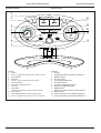 5
5
-
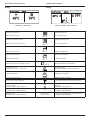 6
6
-
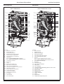 7
7
-
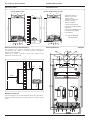 8
8
-
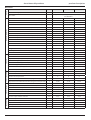 9
9
-
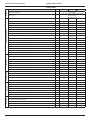 10
10
-
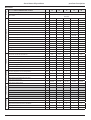 11
11
-
 12
12
-
 13
13
-
 14
14
-
 15
15
-
 16
16
-
 17
17
-
 18
18
-
 19
19
-
 20
20
-
 21
21
-
 22
22
-
 23
23
-
 24
24
-
 25
25
-
 26
26
-
 27
27
-
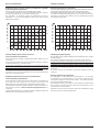 28
28
-
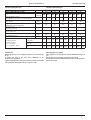 29
29
-
 30
30
-
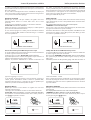 31
31
-
 32
32
-
 33
33
-
 34
34
-
 35
35
-
 36
36
-
 37
37
-
 38
38
-
 39
39
-
 40
40
-
 41
41
-
 42
42
-
 43
43
-
 44
44
-
 45
45
-
 46
46
-
 47
47
-
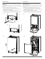 48
48
-
 49
49
-
 50
50
-
 51
51
-
 52
52


in altre lingue
- English: Ariston GENUS Datasheet
Documenti correlati
Altri documenti
-
 Unical KUTter B inox Manuale utente
-
Ferroli PEGASUS D 30 K 100 LN Instructions For Use, Installation And Maintenance
-
Master BF35-BF78-BF105 Manuale del proprietario
-
Radiant RK 55 Manuale utente
-
Robur K18 Use Manual
-
-
Riello FAMILY EXTERNA 25 KIS Installer Manual
-
DeLOCK 65961 Scheda dati
-
elco THISION L EVO Operation and Maintenance Manual
-
Alpha FlowSmart Guida d'installazione
