ProLights 60 W moving spot Manuale utente
- Categoria
- Stroboscopi
- Tipo
- Manuale utente
Questo manuale è adatto anche per

USER MANUAL
MANUALE UTENTE
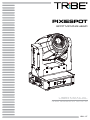
PIXIESPOT
SPOT MOVING HEAD
EN - IT

All rights reserved by Music & Lights S.r.l. No part of this instruction manual may be
reproduced in any form or by any means for any commercial use.
In order to improve the quality of products, Music&Lights S.r.l. reserves the right to modify the
characteristics stated in this instruction manual at any time and without prior notice.
All revisions and updates are available in the ‘manuals’ section on site www.musiclights.it
REV.003-06/17

1
PIXIESPOT
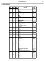
TABLE OF CONTENTS
Safety
General instructions
Warnings and installation precautions
1 Introduction
1. 1 Description
1. 2 Technical specications
1. 3 Operating elements and connections
2 Installation
2. 1 Mounting
3 Functions and settings
3. 1 Operation
3. 2 Basic
3. 3 Menu structure
3. 4 DMX addressing
3. 5 Connection of the DMX line
3. 6 Construction of the DMX termination
3. 7 DMX channels
3. 8 DMX conguration
3. 9 Autoshow
3. 10 Focus adjustment
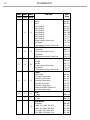
3. 11 Motor settings
3. 12 Fixture settings
3. 13 Display settings
3. 14 Fixture test
3. 15 Reset functions
3. 16 Fixture informations
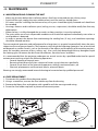
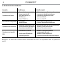
4 Maintenance
4. 1 Maintenance and cleaning the unit
4. 2 Fuse replacement
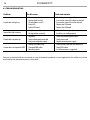
4. 3 Trouble shooting
2
2
4
4
6
7
8
8
9
12
13
13
14
17
17
17
17
18
18
18
19
19
20
20
21
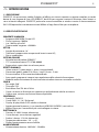
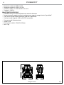
• PIXIESPOT
• Mount bracket
• Power supply cable and signal cable
• Safety rope
• User manual
Packing content

PIXIESPOT
2
WARNING! Before carrying out any operations with the unit, carefully read this instruction
manual and keep it with cure for future reference. It contains important information about
the installation, usage and maintenance of the unit.
SAFETY
General instruction
• The products referred to in this manual conform to the European Community Directives and are there-
fore marked with .
• The unit is supplied with hazardous network voltage (230V~). Leave servicing to skilled personnel only.
Never make any modications on the unit not described in this instruction manual, otherwise you will
risk an electric shock.
• Connection must be made to a power supply system tted with ecient earthing (Class I appliance ac-
cording to standard EN 60598-1). It is, moreover, recommended to protect the supply lines of the units
from indirect contact and/or shorting to earth by using appropriately sized residual current devices.
• The connection to the main network of electric distribution must be carried out by a qualied electrical
installer. Check that the main frequency and voltage correspond to those for which the unit is designed
as given on the electrical data label.
• This unit is not for home use, only professional applications.
• Never use the xture under the following conditions:
- in places wet;
- in places subject to vibrations or bumps;
- in places with an ambient temperature of over 45°C.
• Make certain that no inammable liquids, water or metal objects enter the xture.
• Do not dismantle or modify the xture.
• All work must always be carried out by qualied technical personnel. Contact the nearest sales point for
an inspection or contact the manufacturer directly.
• If the unit is to be put out of operation denitively, take it to a local recycling
plant for a disposal which is not harmful to the environment.
Warnings and installation precautions
• If this device will be operated in any way dierent to the one described in this manual, it may suer
damage and the guarantee becomes void. Furthermore, any other operation may lead to dangers like
short circuit, burns, electric shock, etc.
• Before starting any maintenance work or cleaning the projector, cut o power from the main supply.
• Always additionally secure the projector with the safety rope. When carrying out any work, always com-
ply scrupulously with all the regulations (particularly regarding safety) currently in force in the country
in which the xture’s being used.
• For inside use only. Not designed for outside use.
• The minimum distance between the xture and surrounding walls must be more than 50 cm and the
air vents at the housing must not be covered in any case.
• Install the xture in a well ventilated place.
• Keep any inammable material at a safe distance from the xture.
• The maximum temperature that can be reached on the external surface of the tting, in a thermally
steady state, is high. After power o, please cool down over 15 minutes.
• Shields, lenses or ultraviolet screens shall be changed if they have become damaged to such an extent
that their eectiveness is impaired.
• The lamp (LED) shall be changed if it has become damaged or thermally deformed.
• Never look directly at the light beam. Please note that fast changes in lighting, e. g. ashing light, may
trigger epileptic seizures in photosensitive persons or persons with epilepsy.

3
PIXIESPOT
- 1 - INTRODUCTION
1.1 DESCRIPTION
PIXIESPOT was the rst TRIBE spot moving head to deliver a full spectrum chromatic synthesis, equipped
with a 60W RGBW/FC LED light source to perform limitlessbrightness, intense and saturated colours as
well as proper whites.PIXIESPOT can be also controlled wireless through the optional USB WIFI transceiver
in combination with WIFIBOX and the SmartColor app.
1.2 TECHNICAL SPECIFICATIONS
LIGHT SOURCE
• Source: 60W RGBW Osram LED
• Luminous ux: 1069lm
• Lux: 1682lux @3m full
• Source life expectancy: >50.000 h
OPTICS
• Beam angle: 18°
• Lens type: high-quality glass lens optics
• Focus: motorised
COLOUR SYSTEM
• Colour mixing: RGBW/FC
• CTC: linear CTO correction 2700~6000K
• Colour wheel: virtual colour wheel with presets
DYNAMIC EFFECTS
• Rotating gobos: 7 rotating gobos + open, interchangeable
• Gobo size: gobo Ø 16,9 mm - img Ø 14 mm - 2 mm
• Circular prism: 3f with bi-directional rotation
• Auto mode: built-in programs with execution speed adjustment
• Sound mode: music activation through internal microphone and sensitivity control
BODY
• Pan angle: 540°
• Tilt angle: 270°
• Pan/Tilt resolution: 8/16 bit
• Body: aluminium structure with hi-resistance polycarbonate cover
• Body colour: black, white nishing available
CONTROL
• Protocols: DMX512
• DMX channels: 15 / 18 / 23channel
• Display: black OLED high resolution display
• Firmware upgrade: yes, via USB-DMX interface (UPBOX1) not included
• Master/Slave: for synchronized operation of more units linked in a chain
ELECTRONICS
• Dimmer: linear 0~100% electronic dimmer
• Dimmer curves: dierent dimming curves available
• Strobe / shutter: 1/28 Hz, electronic
• Operating temperature: -10° ~ +45°
• Flicker: icker free operation

PIXIESPOT
4
ELECTRICAL
• Power supply: 100-240V – 50/60Hz
• Power consumption (at 230V): 118W
• Power consumption (at 120V): 120,3W
• Output (at 230V): 17 units on a single power line
• Output (at 120V): 9
PHYSICAL
• Cooling: forced air with low noise fan
• Sospension and xing: any position with quick-lock omega brackets
• Data: USB port for USB WIFI transmitter (optional)
• Signal connection: XLR 3p IN/OUT connectors
• Power connection: IEC IN/OUT connectors
• IP rating: 20
• Dimensions (WxHxD): 253x352x192mm
• Weight: 7kg
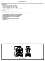
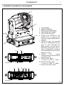
Technical drawing Fig.1
352
253
192

5
PIXIESPOT
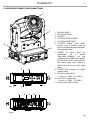
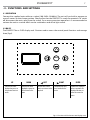
1. MOVING HEAD
2. REVOLVING ARM
3. HANDLE
4. LED INDICATOR "POWER"
5. LED INDICATOR "DMX"
6. CONTROL PANEL with OLED
display and 5 button used to
access the control panel functions
and manage them.
7. POWER IN mains plug for
connection to a socket
(100-240V~/50-60Hz) via the
supplied mains cable. The support
for the mains fuse is located near
the mains plug. Only replace a
blown fuse by one of the same
type.
8. POWER OUT: connect to supply
power to the
9. DMX IN (3 poles XLR ):
1 = mass, 2 = DMX -, 3 = DMX +
10. DMX OUT (3 poles XLR):
1= mass, 2 = DMX -, 3 = DMX +
11. Universal Serial Bus (USB)
1.3 OPERATING ELEMENTS AND CONNECTIONS
Fig.2
View A
View B
spot
4
7
9
11
10
8
6
A
2
1
B
5
3
Power
DMX
Enter

PIXIESPOT
6
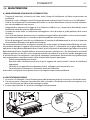
- 2 - INSTALLATION
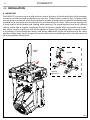
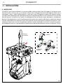
2.1 MOUNTING
The PIXIESPOT may be set up on a solid and even surface. By means of the xing facilities of the baseplate,
the unit can also be mounted upside down to a cross arm. The base plate is shown in g.3. For xing, stable
mounting clips are required. According to the gure, the bolts of the brackets are placed into the openings
provided in the base plate and turned clockwise until they lock (to the stop). Always ensure that the unit
is rmly xed to avoid vibration and slipping while operating. The mounting place must be of sucient
stability and be able to support a weight of 10 times of the unit’s weight. When carrying out any installa-
tion, always comply scrupulously with all the regulations (particularly regarding safety) currently in force
in the country in which the xture’s being used. Always additionally secure the projector with the safety
rope from falling down. For this purpose, fasten the safety rope at a suitable position so that the maximum
fall of the projector will be 20 cm.
CLAMP
SAFETY
CABLE
OMEGA
BRACKETS
Fig.3

7
PIXIESPOT
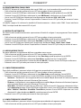
- 3 - FUNCTIONS AND SETTINGS
3.1 OPERATION
Connect the supplied main cable to a socket (100-240V~/50-60Hz). The unit will run built-in program to
reset all motors to their home position. Shortly after that the PIXIESPOT is ready for operation. To switch
o, disconnect the mains plug from the socket. For a more convenient operation it is recommended to
connect the unit to a socket which can be switched on and o via light switch.
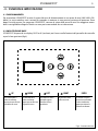
3.2 BASIC
The PIXIESPOT has a OLED display and 5 button used to access the control panel functions and manage
them (g.4).
Fig.4 - Functions of the buttons and display icons
UP DOWN LEFT RIGHT ENTER
Increases the value
displayed or passes to
the previous item in a
menu
Decreases the value
displayed or passes to
the next item in the
menu
To enter in the main
menù or to return to the
top level
Commute from units,
tens, hundred in the
menu
Conrms the displayed
value, or activates the
displayed function, or
enters the successive
menu
Enter

PIXIESPOT
8
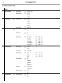
3.3 MENU STRUCTURE
MENU
1 DMX Functions
ð
DMX Address
ð
Value (1-512)
DMX Channels
ð
15 CH
18 CH
23 CH
2 Show setup
ð
Show Mode
ð
Show 1
Show 2
Show 3
Show 4
Focus Adjust
ð
000 - 255
3 Motor Setup
ð
Pan Inverse
ð
No
Yes
Tilt Inverse
ð
No
Yes
Motor Oset
ð
Pan Oset
ð
000 - 255
Tilt Oset
ð
000 - 255
Gobo Oset
ð
000 - 255
Prism Oset
ð
000 - 255
Focus Oset
ð
000 - 255
4 System Setup Master/Slave
ð
Master
Slave
Sound Sence
ð
000 - 100
White Balance
ð
Red
ð
125 - 255
Green
ð
125 - 255
Blue
ð
125 - 255
Dimmer Mode
ð
O
Dimmer 1
Dimmer 2
Dimmer 3
Fan Mode
ð
Auto Speed
High Speed
Factory Setting
ð
No
Yes
5 Display Setup
ð
Display Inverse
ð
No
Yes

9
PIXIESPOT
Back Light
ð
On
10s
20s
30s
Warn Cue
ð
O
On
6 Test Setup
ð
Auto Test
ð
Manual Test
ð
Pan
ð
000 - 255
Pan Fine
ð
000 - 255
Tilt
ð
000 - 255
Tilt Fine
ð
000 - 255
Pan/Tilt Speed
ð
000 - 255
Dimmer
ð
000 - 255
Shutter
ð
000 - 255
Red
ð
000 - 255
Green
ð
000 - 255
Blue
ð
000 - 255
White
ð
000 - 255
Gobo
ð
000 - 255
RGobo
ð
000 - 255
Prism
ð
000 - 255
RPrism
ð
000 - 255
Focus
ð
000 - 255
7 Reset Setup
ð
Auto reset
Manual Reset
ð
Pan Reset
ð
No
Yes
Tilt Reset
ð
No
Yes
Gobo Reset
ð
No
Yes
Prism Reset
ð
No
Yes
Focus Reset
ð
No
Yes

PIXIESPOT
10
8 Information
ð
Fixture Time
ð
0 - 9999
Software Version
ð
DISP V 1.0
CTR - XY V 1.0
CTR - LED V 1.0
LED Temperature
ð
58°C

11
PIXIESPOT
Several units may be interconnected; follow the instructions below:
1. Connect the DMX OUT of the master unit via 3-pole XLR cable to the DMX IN of the rst slave unit.
2. Connect the DMX OUT of the rst slave unit to the DMX IN of the second slave unit, etc. until all units
are connected in a chain.
Use standard DMX cables to daisy chain your units together via the DMX connector on the rear of the
units. For longer cable runs we suggest a terminator at the last xture (see page 13).
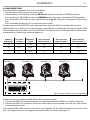
3.4 DMX ADDRESSING
To set DMX addressing follow the instructions below:
• Press the button LEFT to enter the menu mode.
• Use the buttons UP/DOWN to select the DMX Functions item. Press the button ENTER to conrm.
• Press the buttons UP/DOWN to select the DMX Address item. Then press the button ENTER to conrm.
• Press the buttons UP/DOWN to select the desired value 001-512; Then press the button ENTER to con-
rm.
• Press repeatedly the button LEFT to return the menu mode.
To able to operate the PIXIESPOT with a light controller, adjust the DMX start address for the rst a
DMX channel. If e. g. address 33 on the controller is provided for controlling the function of the rst DMX
channel, adjust the start address 33 on the PIXIESPOT. The other functions of the light eect panel are then
automatically assigned to the following addresses.
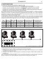
Fig.5 - Example 15 DMX channels conguration
. . . . . . . . . . . .
DMX512 Controller
DMX Address: 78DMX Address: 48DMX Address: 33 DMX Address: 63
Number of
DMX channels
Start address
(example)
DMX Address
occupied
Next possible start
address for unit No. 1
Next possible start
address for unit No. 2
Next possible start
address for unit No. 3
15 33 33-47 48 63 78
18 33 33-50 51 69 87
23 33 33-55 56 79 102

PIXIESPOT
12
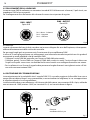
Fig.6
Fig.7
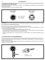
3.5 CONNECTION OF THE DMX LINE
DMX connection employs standard XLR connectors. Use shielded pair-twisted cables with 120Ω imped-
ance and low capacity.
The following diagram shows the connection mode:
ATTENTION
The screened parts of the cable (sleeve) must never be connected to the system’s earth, as this would
cause faulty xture and controller operation.
Over long runs can be necessary to insert a DMX level matching amplier.
For those connections the use of balanced microphone cable is not recommended because it cannot
transmit control DMX data reliably.
• Connect the controller DMX input to the DMX output of the rst unit.
• Connect the DMX output to the DMX input of the following unit. Connect again the output to the input
of the following unit until all the units are connected in chain.
• When the signal cable has to run longer distance is recommended to insert a DMX termination on the
last unit.
3.6 CONSTRUCTION OF THE DMX TERMINATION
The termination avoids the risk of DMX 512 signals being reected back along the cable when they reach-
es the end of the line: under certain conditions and with certain cable lengths, this could cause them to
cancel the original signals.
The termination is prepared by soldering a 120Ω 1/4 W resistor between pins 2 and 3 of the 3-pin male XLR
connector, as shown in gure.
DMX - OUTPUT
XLR socket
DMX - INPUT
XLR plug
Pin1 : GND - Shield
Pin2 : - Negative
Pin3 : + Positive
Example:
3 pin XLR connector

13
PIXIESPOT
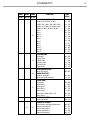
3.7 DMX CHANNELS
MODE MODE MODE
FUNCTION DMX
Value
15 Ch 18 Ch 23 Ch
1 1 1
PAN
0~100% 000 - 255
2 2 2
PAN FINE
0~100% 000 - 255
3 3 3
TILT
0~100% 000 - 255
4 4 4
TILT FINE
0~100% 000 - 255
5 5 5
PAN/TILT SPEED
Fast to slow 000 - 255
6 6 6
SPECIAL FUNCTION
No function
Reset all (Hold 3 Seconds)
No function
000 - 199
200 - 209
210 - 255
7 7 7
RED
0~100% 000 - 255
8 8 8
GREEN
0~100% 000 - 255
9 9 9
BLUE
0~100% 000 - 255
10 10 10
WHITE
0~100% 000 - 255
11 11
COLOR
No function
Red
Yellow
Green
Cyan
Blue
Magenta
White
Full
Clockwise rotation (Fast to Slow)
Stop Run
Counterclockwise rotation (Slow to Fast)
000 - 007
008 - 022
023 - 037
038 - 052
053 - 067
068 - 082
083 - 097
098 - 112
113 - 127
128 - 189
190 - 193
194 - 255
11 12 12
GOBO
Open
Gobo 1
Gobo 2
Gobo 3
Gobo 4
000 - 007
008 - 015
016 - 023
024 - 031
032 - 039

PIXIESPOT
14
MODE MODE MODE
FUNCTION DMX
Value
15 Ch 18 Ch 23 Ch
12 12
Gobo 5
Gobo 6
Gobo 7
Gobo 1 Shaking
Gobo 2 Shaking
Gobo 3 Shaking
Gobo 4 Shaking
Gobo 5 Shaking
Gobo 6 Shaking
Gobo 7 Shaking
Clockwise rotation (Fast to Slow)
Stop Rotation
Counterclockwise rotation (Slow to Fast)
040 - 047
048 - 055
056 - 063
064 - 073
074 - 082
083 - 091
092 - 100
101 - 109
110 - 118
119 - 127
128 - 189
190 - 193
194 - 255
12 13 13
GOBO ROTATION
Stop Rotation
Clockwise rotation (Fast to Slow)
Stop Rotation
Counterclockwise rotation (Slow to Fast)
000 - 127
128 - 129
190 - 193
194 - 255
13 14 14
PRISM
Prism O
Prism On
Clockwise rotation (Fast to Slow)
Stop Rotation
Counterclockwise rotation (Slow to Fast)
000 - 010
011 - 127
128 - 189
190 - 193
194 - 255
14 15 15
STROBE
Shutter Closed
No Function (Shutter open)
Strobe Eect (Slow to Fast)
No function (Shutter open)
Pulse-eect in sequence
No function (Shutter open)
Random Strobe Eect (Slow to Fast)
No Function (Shutter open)
000 - 031
032 - 063
064 - 095
096 - 127
128 - 159
160 - 191
192 - 223
224 - 255
15 16 16
FOCUS
0~100% 000 - 255
17 17
DIMMER
0~100% 000 - 255
18
COLOR MACRO
No Function
R:100% / G:0~100% / B:0 / W:0
R:100%~0 / G:100% / B:0 / W:0
R:0 / G:100% / B:0~100% / W:0
R:0 / G:100%~0 / B:100% / W:0
000 - 010
011 - 030
031 - 050
051 - 070
071 - 090

15
PIXIESPOT
MODE MODE MODE
FUNCTION DMX
Value
15 Ch 18 Ch 23 Ch
18
R:0~100% / G:0 / B:100% / W:0
R:100% / G:0 / B:100%~0 / W:0
R:100% / G:0~100% / B:0~100% / W:0
R:100%~0 / G:100%~0 / B:100% / W:0
R:100% / G:100% / B:100% / W:100%
Color 1
Color 2
Color 3
Color 4
Color 5
Color 6
Color 7
Color 8
Color 9
Color 10
Color 11
091 - 110
111 - 130
131 - 150
151 - 170
171 - 200
201 - 205
206 - 210
211 - 215
216 - 220
221 - 225
226 - 230
231 - 235
236 - 240
241 - 245
246 - 250
251 - 255
19
AUTO PROGRAM
No Function
4 Colours Snap
4 Colours Fade
15 Colours Snap
15 Colours Fade
Sound Control
000 - 010
011 - 070
071 - 130
131 - 190
191 - 250
251 - 255
20
AUTO PROGRAM SPEED
Speed (Slow to Fast)
SOUND SENSITIVITY
Sound Sensitivity OFF
Control the Sound Sensitivity
000 - 010
000 - 010
011 - 255
21
MOTOR SHOW
No Function
Motor Show 1
Motor Show 2
Motor Show 3
Motor Show 4
Motor Show 5 (Motor Show 1 - 4)
Motor Show 6
000 - 010
011 - 058
059 - 106
107 - 154
155 - 202
203 - 250
251 - 255
22
MOTOR SHOW SPEED
Speed (Slow to Fast) 000 - 255
18 23
DIMMER SPEED MODE
Preset dimmer speed from display menu
Dimmer speed mode o
Dimmer speed mode 1
Dimmer speed mode 2
Dimmer speed mode 3
000 - 051
052 - 101
102 - 152
153 - 203
204 - 255

PIXIESPOT
16
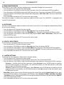
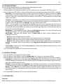
3.8 DMX CONFIGURATION
The PIXIESPOT has 3 DMX channels congurations selectable through the control panel.
• Press the button LEFT to enter the menu mode.
• Use the buttons UP/DOWN to select the DMX Functions item. Press the button ENTER to conrm.
• Press the buttons UP/DOWN to select the DMX Channels item. Then press the button ENTER to conrm.
• Press the buttons UP/DOWN to select the desired conguration 15CH - 18CH - 23CH. ; Then press the button
ENTER to save.
• Press repeatedly the button LEFT to return the menu mode.
The tables on page 14 indicate the operating mode and DMX value. The PIXIESPOT is equipped with
3-pole XLR connections.
3.9 AUTOSHOW
To enter in the automatic mode and allow to the unit to carry out its show program independently follow
the instructions below:
• Press the button LEFT to enter the menu mode.
• Use the buttons UP/DOWN to select the Show setup item. Press the button ENTER.
• Press the buttons UP/DOWN to select the Show Mode item. Then press the button ENTER to conrm.
• Press the buttons UP/DOWN to select the desired program Show1 - Show2 - Show3-Show4 ; Then press the
button ENTER to save.
• Press repeatedly the button LEFT to return the menu mode.
3.10 FOCUS ADJUSTMENT
To set the focus regulation follow the instructions below:
• Press the button LEFT to enter the menu mode.
• Use the buttons UP/DOWN to select the Show setup item. Press the button ENTER.
• Press the buttons UP/DOWN to select the Focus adjust item. Then press the button ENTER to conrm.
• Press the buttons UP/DOWN to select the desired values (000-255); Then press the button ENTER to save.
• Press repeatedly the button LEFT to return the menu mode.
3.11 MOTOR SETTINGS
To change the unit parameters follow the instructions below:
• Press the button LEFT to enter the menu mode.
• Use the buttons UP/DOWN to select the Motor Setup item. Press the button ENTER.
• Press the buttons UP/DOWN to select the desired option item and press the button ENTER to conrm:
- Pan Inverse - Used for reversing Pan movement. Select Pan Inverse, press ENTER button to conrm,
present mode will blink on the display, use UP/DOWN button to select No (normal) or Yes (pan
inverse), press ENTER button to store.
- Tilt Inverse - Used for reversing tilt movement. Select Tilt Inverse, press ENTER button to conrm, present
mode will blink on the display, use UP/DOWN button to select No (normal) or Yes (tilt inverse), press
ENTER button to store.
• Motor Oset - Allows you to set an oset for the pan/tilt motor. After selecting Motor Setup function press
button ENTER to conrm. Use the buttons UP/DOWN to select Pan Oset - Tilt Oset - Gobo Oset - Prism Oset
- Focus Oset and press the button ENTER. Set through the directional buttons the desired value (000-255).
Then press the button ENTER.
• Press repeatedly the button LEFT to return the menu mode.

17
PIXIESPOT
3.12 FIXTURE SETTINGS
You can change the parameters for the device by following these steps:
• Press the button LEFT to enter the menu mode.
• Use the buttons UP/DOWN to select the System setup item. Press the button ENTER to conrm.
• Press the buttons UP/DOWN to select the desired option item and press the button ENTER to conrm:
- Master/Slave - This conguration allows to connect many units PIXIESPOT. The rst will be set as Master
and the others will work as Slave with the same eect. Press the buttons UP/DOWN to set the units as
master or slave. Press the button ENTER to conrm. Use PIXIESPOT DMX connectors and XLR cable
to do a units chain.
- Sound Sence - Microphone sensibility for the control through musical command in autoshow modal-
ity. After selecting Sound Sence function press the button ENTER to conrm. Use the buttons UP/
DOWN to select the desired value (000-100). Then press the button ENTER.
NOTE - In music mode, via its integrated microphone, the unit can be controlled by music with a
clear rhythm in the bass range. If the music control should not work optimally, increase the volume
or reduce the distance between the sound source and the light eect unit or alternatively increase
the sensitivity of the microphone.
- White Balance - White Balance function. Select the White Balance function to set the white balance by
changing the values (125-255) of the colors Red, Green and Blue.
- Dimmer Mode - Adjusting the dimmer. Enter in Dimmer Mode to select specic dimming curve.
Particularly when set:
• O: The increase in light intensity is linear
• Dimmer 1: Light intensity control is nger at low levels and coarse at high levels.
• Dimmer 2: Light intensity control is nger at high levels and coarse at low levels.
• Dimmer 3: Light intensity control is nger at low levels and high levels and coarse at medium levels.
- Fan Mode - Fan speed. Select the desired fan speed High Speed or Auto Speed through the button UP/
DOWN.
- Factory Settings - Factory reset. Select Factory Settings function and then Yes to restore all values to the
original factory settings.
• Press repeatedly the button LEFT to return the menu mode.
3.13 DISPLAY SETTINGS
• Press the button LEFT to enter the menu mode.
• Press the buttons UP/DOWN to select the Display setup item. Then press the button ENTER.
• Press the buttons UP/DOWN to select the desired option item and press the button ENTER to conrm:
- Display Inverse - Used for reversing display. Select Display Inverse, press ENTER button to conrm, present
mode will blink on the display, use UP/DOWN button to select No (normal display) or Yes (inverse dis-
play), press ENTER button to store.
- Back Light - Display backlight. Select Back Light, press ENTER button to conrm. Use the UP/DOWN keys
to select On for display always on or Off for setting display o one minute after the exit from the menu.
- Warn Cue - Select Warn Cue, press ENTER button to conrm, present mode will blink on the display, use
UP/DOWN button to select No (Normal) or Yes (display will show the error warning when the unit
went wrong).
• Press repeatedly the button LEFT to return the menu mode.
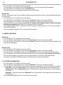
3.14 FIXTURE TEST
Auto Test
Allow checking the proper functioning of the unit. Start the automatic test in the following way:

PIXIESPOT
18
• Press the button LEFT to enter the menu mode.
• Use the buttons UP/DOWN to select the Test Setup item. Press the button ENTER to conrm.
• Press the buttons UP/DOWN to select the Auto Test item.
• To conrm and start the automatic test press the ENTER button.
Manual Test
It allows to do adjustments on the eects through comands pannel to obtain a perfect balance between
the projectors.
• Press the button LEFT to enter the menu mode.
• Press the buttons UP/DOWN to select the item Test Setup. Then press the button ENTER.
• Press the buttons UP/DOWN to select the Manual Test item. Then press the button ENTER.
• Select the eect you want change (Pan, Pan Fine, Tilt, Tilt Fine, P/T Speed, Dimmer, Shutter, Red, Green, Blue, White,
Gobo, RGobo, Prism, Rprism, Focus).Then press the button ENTER to conrm
• Use the directional buttons to calibrate the eect setting a value between 0 - 255. Then press the but-
ton ENTER to conrm
• Press repeatedly the button LEFT to return the menu mode.
3.15 RESET FUNCTIONS
Auto reset
• Press the button LEFT to enter the menu mode.
• Press the buttons UP/DOWN to select the item Reset Setup. Then press the button ENTER.
• Press the buttons UP/DOWN to select the item Auto reset. Then press the button ENTER to conrm and
to restart automatically
Manual reset
• Press the button LEFT to enter the menu mode.
• Press the buttons UP/DOWN to select the item Reset Setup. Then press the button ENTER.
• Press the buttons UP/DOWN to select the item Manual reset. Then press the button ENTER to conrm.
• Press the buttons UP/DOWN to select the function you want reset between Pan, Tilt, Gobo, Prism e Focus. In
this way selecting Yes it is possible to start a preset program to restore the selected function.
• Then press the button ENTER to conrm, waiting the reactivation of the function.
3.16 FIXTURE INFORMATION
• Press the button LEFT to enter the menu mode.
• Press the buttons UP/DOWN to select the item Information. Then press the button ENTER.
• Press the buttons UP/DOWN to select the desired option item and press the button ENTER to conrm:
- Fixture Time - Through the Fixture Time function you can display the operating time of the projector.
- Software Version - Select Software Version, press ENTER button to conrm, rmware version will show on
the display.
- Temperature - Through the function Temperature can be displayed on the display the temperature of
the device in ° C.
• Press repeatedly the button LEFT to return the menu mode.
La pagina si sta caricando...
La pagina si sta caricando...
La pagina si sta caricando...
La pagina si sta caricando...
La pagina si sta caricando...
La pagina si sta caricando...
La pagina si sta caricando...
La pagina si sta caricando...
La pagina si sta caricando...
La pagina si sta caricando...
La pagina si sta caricando...
La pagina si sta caricando...
La pagina si sta caricando...
La pagina si sta caricando...
La pagina si sta caricando...
La pagina si sta caricando...
La pagina si sta caricando...
La pagina si sta caricando...
La pagina si sta caricando...
La pagina si sta caricando...
La pagina si sta caricando...
La pagina si sta caricando...
La pagina si sta caricando...
La pagina si sta caricando...
La pagina si sta caricando...
La pagina si sta caricando...
La pagina si sta caricando...
La pagina si sta caricando...
-
 1
1
-
 2
2
-
 3
3
-
 4
4
-
 5
5
-
 6
6
-
 7
7
-
 8
8
-
 9
9
-
 10
10
-
 11
11
-
 12
12
-
 13
13
-
 14
14
-
 15
15
-
 16
16
-
 17
17
-
 18
18
-
 19
19
-
 20
20
-
 21
21
-
 22
22
-
 23
23
-
 24
24
-
 25
25
-
 26
26
-
 27
27
-
 28
28
-
 29
29
-
 30
30
-
 31
31
-
 32
32
-
 33
33
-
 34
34
-
 35
35
-
 36
36
-
 37
37
-
 38
38
-
 39
39
-
 40
40
-
 41
41
-
 42
42
-
 43
43
-
 44
44
-
 45
45
-
 46
46
-
 47
47
-
 48
48


ProLights 60 W moving spot Manuale utente
- Categoria
- Stroboscopi
- Tipo
- Manuale utente
- Questo manuale è adatto anche per
in altre lingue
Documenti correlati
-
ProLights 60W moving spot Scheda dati
-
-
-
-
-
-
-
-
-
