Denon DN-X1500 Manuale utente
- Categoria
- Mixer audio
- Tipo
- Manuale utente
Questo manuale è adatto anche per

DJ MIXER
DN-X1500
OPERATING INSTRUCTIONS
MODE D’EMPLOI
FOR ENGLISH READERS PAGE 2 ~ PAGE 13
POUR LES LECTEURS FRANCAIS PAGE 14 ~ PAGE 22

2
CAUTION:
TO REDUCE THE RISK OF ELECTRIC SHOCK, DO NOT REMOVE COVER (OR
BACK). NO USER SERVICEABLE PARTS INSIDE. REFER SERVICING TO
QUALIFIED SERVICE PESONNEL.
The lightning flash with arrowhead symbol, within an equilateral triangle, is intended to
alert the user to the presence of uninsulated “dangerous voltage” within the product’s
enclosure that may be of sufficient magnitude to constitute a risk of electric shock to
persons.
The exclamation point within an equilateral triangle is intended to alert the user to the
presence of important operating and maintenance (servicing) instructions in the literature
accompanying the appliance.
WARNING: TO PREVENT FIRE OR SHOCK HAZARD, DO NOT EXPOSE THIS
APPLIANCE TO RAIN OR MOISTURE.
CAUTION:
1. Handle the power supply cord carefully
Do not damage or deform the power supply cord. If it
is damaged or deformed, it may cause electric shock
or malfunction when used. When removing from wall
outlet, be sure to remove by holding the plug
attachment and not by pulling the cord.
2. Do not open the top cover
In order to prevent electric shock, do not open the top
cover.
If problems occur, contact your DENON dealer.
3. Do not place anything inside
Do not place metal objects or spill liquid inside the DJ
mixer.
Electric shock or malfunction may result.
Please, record and retain the Model name and serial
number of your set shown on the rating label.
Model No. DN-X1500 Serial No.
This device complies with Part 15 of the FCC Rules.
Operation is subject to the following two conditions:
(1) This device may not cause harmful interference,
and (2) this device must accept any interference
received, including interference that may cause
undesired operation.
This Class B digital apparatus meets all requirements
of the Canadian Interference-Causing Equipment
Regulations.
Cet appareil numérique de la classe B respecte toutes
les exigences du Règlement sur le matériel brouilleur
du Canada.
CAUTION
TO PREVENT ELECTRIC SHOCK, MATCH
WIDE BLADE OF PLUG TO WIDE SLOT,
FULLY INSERT.
ATTENTION
POUR ÉVITER LES CHOCS ÉLECTRIQUES,
INTERODUIRE LA LAME LA PLUS LARGE
DE LA FICHE DANS LA BORNE
CORRESPONDANTE DE LA PRISE ET
POUSSER JUSQU’ AU FOND.
CAUTION
RISK OF ELECTRIC SHOCK
DO NOT OPEN
LABELS:
SAFETY INSTRUCTIONS
1. Read Instructions – All the safety and operating instructions
should be read before the product is operated.
2. Retain Instructions – The safety and operating instructions
should be retained for future reference.
3. Heed Warnings – All warnings on the product and in the
operating instructions should be adhered to.
4. Follow Instructions – All operating and use instructions
should be followed.
5. Cleaning – Unplug this product from the wall outlet before
cleaning. Do not use liquid cleaners or aerosol cleaners.
6. Attachments – Do not use attachments not recommended
by the product manufacturer as they may cause hazards.
7. Water and Moisture – Do not use this product near water –
for example, near a bath tub, wash bowl, kitchen sink, or
laundry tub; in a wet basement; or near a swimming pool;
and the like.
8. Accessories – Do not place this product on an unstable cart,
stand, tripod, bracket, or table. The product may fall,
causing serious injury to a child or adult, and serious
damage to the product. Use only with a cart, stand, tripod,
bracket, or table recommended by the manufacturer, or
sold with the product. Any mounting of the product should
follow the manufacturer’s instructions, and should use a
mounting accessory
recommended by the
manufacturer.
9. A product and cart
combination should be
moved with care. Quick
stops, excessive force,
and uneven surfaces may
cause the product and cart
combination to overturn.
10. Ventilation – Slots and openings in the cabinet are provided
for ventilation and to ensure reliable operation of the
product and to protect it from overheating, and these
openings must not be blocked or covered. The openings
should never be blocked by placing the product on a bed,
sofa, rug, or other similar surface. This product should not
be placed in a built-in installation such as a bookcase or rack
unless proper ventilation is provided or the manufacturer’s
instructions have been adhered to.
11. Power Sources – This product should be operated only
from the type of power source indicated on the marking
label. If you are not sure of the type of power supply to
your home, consult your product dealer or local power
company. For products intended to operate from battery
power, or other sources, refer to the operating instructions.
12. Grounding or Polarization – This product may be equipped
with a polarized alternating-current line plug (a plug having
one blade wider than the other). This plug will fit into the
power outlet only one way. This is a safety feature. If you
are unable to insert the plug fully into the outlet, try
reversing the plug. If the plug should still fail to fit, contact
your electrician to replace your obsolete outlet. Do not
defeat the safety purpose of the polarized plug.
13. Power-Cord Protection – Power-supply cords should be
routed so that they are not likely to be walked on or pinched
by items placed upon or against them, paying particular
attention to cords at plugs, convenience receptacles, and
the point where they exit from the product.
15. Outdoor Antenna Grounding – If an outside antenna or
cable system is connected to the product, be sure the
antenna or cable system is grounded so as to provide some
protection against voltage surges and built-up static
charges. Article 810 of the National Electrical Code,
ANSI/NFPA 70, provides information with regard to proper
grounding of the mast and supporting structure, grounding
of the lead-in wire to an antenna discharge unit, size of
grounding conductors, location of antenna-discharge unit,
connection to grounding electrodes, and requirements for
the grounding electrode. See Figure A.
16. Lightning – For added protection for this product during a
lightning storm, or when it is left unattended and unused
for long periods of time, unplug it from the wall outlet and
disconnect the antenna or cable system. This will prevent
damage to the product due to lightning and power-line
surges.
17. Power Lines – An outside antenna system should not be
located in the vicinity of overhead power lines or other
electric light or power circuits, or where it can fall into such
power lines or circuits. When installing an outside antenna
system, extreme care should be taken to keep from
touching such power lines or circuits as contact with them
might be fatal.
18. Overloading – Do not overload wall outlets, extension
cords, or integral convenience receptacles as this can result
in a risk of fire or electric shock.
19. Object and Liquid Entry – Never push objects of any kind
into this product through openings as they may touch
dangerous voltage points or short-out parts that could
result in a fire or electric shock. Never spill liquid of any
kind on the product.
20. Servicing – Do not attempt to service this product yourself
as opening or removing covers may expose you to
dangerous voltage or other hazards. Refer all servicing to
qualified service personnel.
21. Damage Requiring Service – Unplug this product from the
wall outlet and refer servicing to qualified service personnel
under the following conditions:
a) When the power-supply cord or plug is damaged,
b) If liquid has been spilled, or objects have fallen into the
product,
c) If the product has been exposed to rain or water,
d) If the product does not operate normally by following
the operating instructions. Adjust only those controls
that are covered by the operating instructions as an
improper adjustment of other controls may result in
damage and will often require extensive work by a
qualified technician to restore the product to its normal
operation,
e) If the product has been dropped or damaged in any way,
and
f) When the product exhibits a distinct change in
performance – this indicates a need for service.
22. Replacement Parts – When replacement parts are required,
be sure the service technician has used replacement parts
specified by the manufacturer or have the same
characteristics as the original part. Unauthorized
substitutions may result in fire, electric shock, or other
hazards.
23. Safety Check – Upon completion of any service or repairs
to this product, ask the service technician to perform safety
checks to determine that the product is in proper operating
condition.
24. Wall or Ceiling Mounting – The product should be mounted
to a wall or ceiling only as recommended by the
manufacturer.
25. Heat – The product should be situated away from heat
sources such as radiators, heat registers, stoves, or other
products (including amplifiers) that produce heat.
FIGURE A
EXAMPLE OF ANTENNA GROUNDING
AS PER NATIONAL
ELECTRICAL CODE
ANTENNA
LEAD IN
WIRE
GROUND
CLAMP
ELECTRIC
SERVICE
EQUIPMENT
ANTENNA
DISCHARGE UNIT
(NEC SECTION 810-20)
GROUNDING CONDUCTORS
(NEC SECTION 810-21)
GROUND CLAMPS
POWER SERVICE GROUNDING
ELECTRODE SYSTEM
(NEC ART 250, PART H)
NEC - NATIONAL ELECTRICAL CODE

3
ENGLISH
@1
@3
#2
#1
#3
q
w
e
r
t
y
!4
!2
!0
!1
!3
o
u
i
!6@0 !8!9 !5!7 !7
#5
#6
#5
#6
#5
#6
#5
#6
#4 #7
#0
@7
@8
@5
@6
@4
@9
@2
#9 #9 #9 #9
#8 #8 #8 #8
!6 !6 !6 !6
!0
Unit: mm
Unité: mm
FRANÇAIS
TOP PANEL DIAGRAM / SCHEMA DU PANNEAU SUPERIEUR
DISPLAY / AFFICHAGE
REAR PANEL DIAGRAM / SCHEMA DU PANNEAU ARRIERE
%5 %4 %2
%3 %1
%0 $9 $8 $7 $6
$0
$0
$0
$1 $0
$1
$3 $0
$1 $4 $5$2 $2
$2
^4^5 ^2^3
%6 %9 ^0 ^1%7 %8
327 (12-7/8”)
310 (12-13/64”)
90
(3-35/64”)
20
(25/32”)

4
• DECLARATION OF CONFORMITY
We declare under our sole responsibility that this
product, to which this declaration relates, is in
conformity with the following standards:
EN60065, EN55013, EN55020, EN61000-3-2 and
EN61000-3-3.
Following the provisions of 73/23/EEC,
89/336/EEC and 93/68/EEC Directive.
• ÜBEREINSTIMMUNGSERKLÄRUNG
Wir erklären unter unserer Verantwortung, daß
dieses Produkt, auf das sich diese Erklärung
bezieht, den folgenden Standards entspricht:
EN60065, EN55013, EN55020, EN61000-3-2 und
EN61000-3-3.
Entspricht den Verordnungen der Direktive
73/23/EEC, 89/336/EEC und 93/68/EEC.
• DECLARATION DE CONFORMITE
Nous déclarons sous notre seule responsabilité
que l’appareil, auquel se réfère cette déclaration,
est conforme aux standards suivants:
EN60065, EN55013, EN55020, EN61000-3-2 et
EN61000-3-3.
D’après les dispositions de la Directive
73/23/EEC, 89/336/EEC et 93/68/EEC.
• DICHIARAZIONE DI CONFORMITÀ
Dichiariamo con piena responsabilità che questo
prodotto, al quale la nostra dichiarazione si
riferisce, è conforme alle seguenti normative:
EN60065, EN55013, EN55020, EN61000-3-2 e
EN61000-3-3.
In conformità con le condizioni delle direttive
73/23/EEC, 89/336/EEC e 93/68/EEC.
QUESTO PRODOTTO E’ CONFORME
AL D.M. 28/08/95 N. 548
• DECLARACIÓN DE CONFORMIDAD
Declaramos bajo nuestra exclusiva
responsabilidad que este producto al que hace
referencia esta declaración, está conforme con
los siguientes estándares:
EN60065, EN55013, EN55020, EN61000-3-2 y
EN61000-3-3.
Siguiendo las provisiones de las Directivas
73/23/EEC, 89/336/EEC y 93/68/EEC.
• EENVORMIGHEIDSVERKLARING
Wij verklaren uitsluitend op onze
verantwoordelijkheid dat dit produkt, waarop
deze verklaring betrekking heeft, in
overeenstemming is met de volgende normen:
EN60065, EN55013, EN55020, EN61000-3-2 en
EN61000-3-3.
Volgens de bepalingen van de Richtlijnen
73/23/EEC, 89/336/EEC en 93/68/EEC.
• ÖVERENSSTÄMMELSESINTYG
Härmed intygas helt på eget ansvar att denna
produkt, vilken detta intyg avser, uppfyller
följande standarder:
EN60065, EN55013, EN55020, EN61000-3-2 och
EN61000-3-3.
Enligt stadgarna i direktiv 73/23/EEC, 89/336/EEC
och 93/68/EEC.
NOTE ON USE /
OBSERVATIONS RELATIVES A L’UTILISATION
•Avoid high temperatures.
Allow for sufficient heat dispersion when
installed on a rack.
•Vermeiden Sie hohe Temperaturen.
Beachten Sie, daß eine ausreichend
Luftzirkulation gewährleistet wird, wenn das
Gerät auf ein Regal gestellt wird.
• Eviter des températures élevées
Tenir compte d’une dispersion de chaleur
suffisante lors de l’installation sur une
étagère.
• Evitate di esporre l’unità a temperature alte.
Assicuratevi che ci sia un’adeguata
dispersione del calore quando installate
l’unità in un mobile per componenti audio.
• Evite altas temperaturas
Permite la suficiente dispersión del calor
cuando está instalado en la consola.
•Vermijd hoge temperaturen.
Zorg voor een degelijk hitteafvoer indien het
apparaat op een rek wordt geplaatst.
• Undvik höga temperaturer.
Se till att det finns möjlighet till god
värmeavledning vid montering i ett rack.
•Keep the set free from moisture, water, and
dust.
•Halten Sie das Gerät von Feuchtigkeit,
Wasser und Staub fern.
•Protéger l’appareil contre l’humidité, l’eau et
lapoussière.
•Tenete l’unità lontana dall’umidità, dall’acqua
e dalla polvere.
• Mantenga el equipo libre de humedad, agua
y polvo.
• Laat geen vochtigheid, water of stof in het
apparaat binnendringen.
•Utsätt inte apparaten för fukt, vatten och
damm.
• Do not let foreign objects in the set.
• Keine fremden Gegenstände in das Gerät
kommen lassen.
• Ne pas laisser des objets étrangers dans
l’appareil.
•E’ importante che nessun oggetto è inserito
all’interno dell’unità.
• No deje objetos extraños dentro del equipo.
• Laat geen vreemde voorwerpen in dit
apparaat vallen.
• Se till att främmande föremål inte tränger in i
apparaten.
• Do not let insecticides, benzene, and thinner
come in contact with the set.
• Lassen Sie das Gerät nicht mit Insektiziden,
Benzin oder Verdünnungsmitteln in
Berührung kommen.
• Ne pas mettre en contact des insecticides,
du benzène et un diluant avec l’appareil.
• Assicuratevvi che l’unità non venga in
contatto con insetticidi, benzolo o solventi.
• No permita el contacto de insecticidas,
gasolina y diluyentes con el equipo.
• Laat geen insektenverdelgende middelen,
benzine of verfverdunner met dit apparaat in
kontakt komen.
• Se till att inte insektsmedel på spraybruk,
bensen och thinner kommer i kontakt med
apparatens hölje.
• Unplug the power cord when not using the
set for long periods of time.
•Wenn das Gerät eine längere Zeit nicht
verwendet werden soll, trennen Sie das
Netzkabel vom Netzstecker.
• Débrancher le cordon d’alimentation lorsque
l’appareil n’est pas utilisé pendant de
longues périodes.
• Disinnestate il filo di alimentazione quando
avete l’intenzione di non usare il filo di
alimentazione per un lungo periodo di tempo.
• Desconecte el cordón de energía cuando no
utilice el equipo por mucho tiempo.
• Neem altijd het netsnoer uit het stopkontakt
wanneer het apparaat gedurende een lange
periode niet wordt gebruikt.
• Koppla ur nätkabeln om apparaten inte
kommer att användas i lång tid.
• Do not obstruct the ventilation holes.
•Die Belüftungsöffnungen dürfen nicht
verdeckt werden.
• Ne pas obstruer les trous d’aération.
• Non coprite i fori di ventilazione.
• No obstruya los orificios de ventilación.
• De ventilatieopeningen mogen niet worden
beblokkeerd.
• Täpp inte till ventilationsöppningarna.
• Handle the power cord carefully.
Hold the plug when unplugging the cord.
• Gehen Sie vorsichtig mit dem Netzkabel um.
Halten Sie das Kabel am Stecker, wenn Sie
den Stecker herausziehen.
•Manipuler le cordon d’alimentation avec
précaution.
Tenir la prise lors du débranchement du
cordon.
•Manneggiate il filo di alimentazione con cura.
Agite per la spina quando scollegate il cavo
dalla presa.
•Maneje el cordón de energía con cuidado.
Sostenga el enchufe cuando desconecte el
cordón de energía.
• Hanteer het netsnoer voorzichtig.
Houd het snoer bij de stekker vast wanneer
deze moet worden aan- of losgekoppeld.
• Hantera nätkabeln varsamt.
Håll i kabeln när den kopplas från el-uttaget.
• Never disassemble or modify the set in any
way.
•Versuchen Sie niemals das Gerät
auseinander zu nehmen oder auf jegliche Art
zu verändern.
• Ne jamais démonter ou modifier l’appareil
d’une manière ou d’une autre.
• Non smontate mai, nè modificate l’unità in
nessun modo.
• Nunca desarme o modifique el equipo de
ninguna manera.
• Nooit dit apparaat demonteren of op andere
wijze modifiëren.
•Ta inte isär apparaten och försök inte bygga
om den.
✽ (For sets with ventilation holes)
CAUTION
• The ventilation should not be impeded by covering the
ventilation openings with items, such as newspapers,
table-cloths, curtains, etc.
• No naked flame sources, such as lighted candles,
should be placed on the apparatus.
• Please be care the environmental aspects of battery
disposal.
• The apparatus shall not be exposed to dripping or
splashing for use.
• No objects filled with liquids, such as vases, shall be
placed on the apparatus.

5
ENGLISH
1
MAIN FEATURES
1. Matrix input assignment
8 input sources is freely assignable to each
channels.
2. Penny & Giles Crossfader
Smooth and reliable mixing is excelled by Penny &
Giles Crossfader.
3. Sampler
On-board digital Sampler can record up to 8
seconds CD quality sound. You can seamlessly
Loop this Sampler or play it backwards
(REVERSE). The pitch and output level of Sampler
can be adjusted independently.
4. Internal Effector
Various sound effects can be performed. (DELAY,
ECHO, PAN, TRANS, FILTER, FLANGER, KEY)
5. Auto BPM counter, BPM Lock, TAP and Manual
BPM input
In addition to an Auto BPM counter and Tap
function, the DN-X1500 is also equipped with the
temporarily Lock function of the Auto BPM
counter and the Manual BPM input function.
6. Channel Fader and Crossfader Start
The CD player can be started or stopped simply by
increasing or decreasing the level of the Ch. Fader
or by using the Crossfader left to right or right to
left. (This function can only be used when the
DENON CD players DN-S3000, DN-S5000, DN-
D4000 or etc. is connected to the DN-X1500.)
7. Digital output
The DN-X1500 allows you to record directly to CD-
R, MiniDisc or a hard disk device through it’s
exclusive coaxial digital output.
The digital output maintains a constant 44.1 kHz
signal.
8. Enhanced SEND/RETURN terminals
8 LINE, 3 PHONO, 2 Microphone systems, 2
MASTER outputs, BOOTH output and REC output
are provided independently. Effect SEND/RETURN
terminals are also provided for a external effects
processor.
9. 3-Band equalizer/gain
LOW, MID, HI and GAIN controls are available on
every input channel.
10. Crossfader Contour
This feature allows adjusting the “shape” of the
Crossfader response from a gentle curve for
smooth, long running fades, to the steep pitch
required for top performance cut and scratch
effects.
11. Mic Post
This feature will pass the Mic signal into the
BOOTH, REC output and DIGITAL output signal
path.
In the OFF mode, the Mic signal will not be routed
through the above outputs.
2
INSTALLATION
When the DN-X1500 is installed inside a coffin or DJ
booth, separate it from the foam (sponge), walls or
other equipment to improve heat radiation.
3
PART NAMES AND FUNCTIONS
(Refer to page 3.)
(1) Top panel
q Power operation switch (POWER)
• The power turns on when the button is
switched from the off position (
£) to the on
position (
¢).
• The power turns off when the button is
switched from the on position (
¢) to the off
position (
£).
w MASTER BALANCE control
• Adjusts the L/R balance of the MASTER output.
e MASTER LEVEL control
• Adjusts the level of the MASTER outputs.
r BOOTH ASSIGN switch
• Selects the source of the BOOTH output.
t BOOTH LEVEL control
• Adjusts the level of the BOOTH output.
y SAMPLER ASSIGN switch
• Use this to select the source for Sampler
recording.
u SAMPLER MODE knob
• Use this to set the Sampler playback mode or
edit the Sampler.
• Push this knob during the Sampler playback or
recording, the Sampler playback or recording is
stopped.
i SAMPLER A button
• Push this button, the Sampler recording or
playback starts.
o SAMPLER B button
• Use this to set the Sampler B point.
Min. 2 cm
– TABLE OF CONTENTS –
z
MAIN FEATURES ...............................................5
x
INSTALLATION ...................................................5
c
PART NAMES AND FUNCTIONS ................5 ~ 7
v
CONNECTIONS ..................................................8
b
SPECIFICATIONS................................................9
n
FADER START ..................................................10
m
EFFECTOR........................................................11
,
SAMPLER.........................................................12
.
PFL (Pre Fader Level) .......................................12
⁄0
PRESET ............................................................13
2 ACCESSORIES
Please check to make sure the following items
are included with the main unit in the carton:
q Operating instructions.......................................1
2 INTRODUCTION
Thank you very much for purchasing the DENON DN-X1500 DJ MIXER.
DENON proudly presents this advanced DJ MIXER to audiophiles and music lovers as a further proof of DENON’s
non-compromising pursuit of the ultimate in sound quality. The high quality performance and easy operation are
certain to provide you with many hours of outstanding listening pleasure.
Min. 2 cm
12. PFL (Pre Fader Level)
This feature provides a means to adjust the input
level gain of each channel to avoid over loading. By
making this adjustment in advance will insure a
smooth transition between cross fades or channel
fades.
13. Preset functions
It is possible to customise the machine to your
preference by saving your favourite setting to
internal memory. For items found in the presets,
please see page 13.
Min. 2 cm
Min. 3 mm

6
ENGLISH
!0 CROSSFADER ASSIGN switch
A, B:
• The channel source is assigned to A or B of the
Crossfader.
POST:
• Select when you don’t assign the channel
source into the Crossfader.
!1 EFFECTS ASSIGN switch
• Use this to select the source of the internal
Effector.
!2 MODE PARAMETER knob
• Use this to set the effect mode and parameters.
!3 EFFECTS WET/DRY control
• Use this to adjust the ratio of original and
effected sound.
!4 EFFECTS ON/OFF button
• Use this to switch the internal Effector function
ON and OFF.
!5 TAP button
• TAP:
When you push this button repeatedly, the
AUTO mode turns off and starts measuring your
Beats Per Minute (BPM) by tapping.
• LOCK:
When this button is pressed once while the
auto BPM counter is operating, the data
measured by the auto BPM counter is locked.
• AUTO:
When pushing the TAP button for 1 second,
activates AUTO BPM mode.
The measured BPM is displayed in the BPM
display.
• INPUT BPM:
When the TAP button is pressed and held in for
more than 2 seconds, the BPM input mode is
set and the BPM value can be input directly with
the MODE PARAMETERS knob !2. When the
button is pressed again, the BPM input mode is
turned off.
!6 CUE buttons
• Pressing in any or all of the CUE buttons routes
the respective source to the headphone and
meter cue sections. Pressing multiple buttons
makes it possible to derive mixed sound from
the selected sources.
!7 CROSSFADER START A, B switches
• Use this to switch the Crossfader Start function
ON and OFF.
!8 Crossfader
• Controls the relative output level from the
summed A and B Mixes. When the fader is at its
far left, only the A Mix is heard from the
outputs. As the fader is moved toward the right,
the amount of B Mix is increased and the
amount of A Mix is decreased. When the fader
is centered, equal amounts of A and B Mixes
are routed to the outputs. Fully right is all B Mix
at the outputs.
!9 Source input fader (Ch. Fader)
• Controls the level of the selected Input.
@0 CROSSFADER CONTOUR control
• Allows adjusting the “shape” of the Crossfader
response from a gentle curve for smooth, long
running fades, to the steep pitch required for
top performance cut and scratch effects.
@1 HEADPHONE output jack
• Accepts 1/4” stereo headphone plugs.
@2 HEADPHONE LEVEL control
• Adjusts the volume for the headphones.
@3 HEADPHONE PAN control
• Serves two purposes…In the STEREO mode it
changes the relative levels of the Cue and
Program (CUE MASTER) mixed together in both
earcups. In the SPLIT CUE (MONO) mode it
changes the balance between the Mono Cue in
the left ear cup and the Mono Program
(MASTER) in the right.
@4 SPLIT CUE button
• In the STEREO mode, this button feeds
STEREO Program (CUE MASTER) and Cue to
both earcups, in the SPLIT CUE (MONO) mode,
the headphone circuit provides MONO Cue to
the left ear and MONO Program (MASTER) to
the right.
• In the STEREO mode, the meter indicates the
stereo level in the LEFT and RIGHT Master
Outputs. In the SPLIT CUE (MONO) mode,
mono Cue level is displayed on the Left meter
and mono Program (CUE MASTER) level is
displayed on the Right meter.
• In the SPLIT CUE (MONO) mode, the button is
lit.
@5 EFFECT LOOP WET/DRY control
• Use this to adjust the ratio of original and
effected sound.
@6 CH FADER START switch
• Use this to switch the Channel Fader Start
function ON and OFF.
@7 EFFECT LOOP ASSIGN switch
• Use this to select the source of the external
processor.
@8 EFFECT LOOP ON/OFF button
• Routes the assigned signal through the external
processor attached to the SEND/RETURN
connectors on the rear.
• When the EFFECT is ON, the button is lit.
(When the processor isn’t connected, the
button will blink when activated.)
@9 TALK OVER ON/OFF button
• Use this to switch the Talk Over function ON
and OFF.
• When the button is lit, level of signals except
Mics is attenuated.
• The Talk Over attenuation level can be adjusted
in the Preset mode.
NOTE:
When this button is pushed, volume changes
rapidly.
#0 MIC POST ON/OFF button
• Puts the Mic signals into the BOOTH, REC and
DIGITAL out signal path.
#1 MIC EQ controls
• Contour the frequency response of the MIC
input –12 dB to +12 dB.
At the center position, sound is flat.
#2 MIC LEVEL controls
• Adjusts the level of the Mic signal.
#3 MIC ON/OFF buttons
• When the button is lit, Mic signal is transferred
to output section, otherwise Mic input is muted.
#4 INPUT ASSIGN (Input selectors)
• Select any source from eight inputs
(PHONO1/LINE1, LINE2, PHONO2/LINE3,
LINE4, PHONO3/LINE5, LINE6, LINE7, LINE8)
for each channel independently.
• You also can assign the same input to several
channels for creative mixing.
#5 GAIN (Line input level controls)
• Adjusts the level of the selected input.
• You can adjust each GAIN volume to indicate
0dB on source level meter.
#6 Source EQ controls
• Contour the frequency response of the selected
inputs.
At the center position, sound is flat.
HI and MID:
• Adjusts the high-tone and mid-tone sound –40
dB to +10 dB.
LOW:
• Adjusts the low-tone sound –40 dB to +6 dB.
NOTE:
Clipping may occur if adjustments are set to
harsh.
#7 CUE MASTER level meter
• Displays the output level following MASTER
LEVEL adjustment.
• Can switch between two display mode. See
below @4.
#8 Source level meters
• Displays the input level after adjusted with
GAIN #5 and EQ #6 controls.
NOTE:
If this meter indicates over +12 dB, inputted
sound may be clipped.
#9 EQ ON/OFF buttons
• When this button is lit EQ is on, otherwise EQ is
bypassed.
LINE1
LINE2
LINE3
LINE4
LINE5
LINE6
LINE7
LINE8
• • • • •
INPUT ASSIGN INPUT ASSIGN
CH1 CH4

7
ENGLISH
(2) Rear panel
$0 LINE2, 4, 6, 7, 8 input jacks
• These stereo pairs of unbalanced RCA jacks are
inputs for any line level device.
$1 PHONO1, 2, 3 / LINE1, 3, 5 input
jacks
• These stereo pairs of unbalanced RCA jacks are
inputs for a PHONO (RIAA) stage for magnetic
(MM) cartridges or a LINE stage suitable for any
device, such as a CD player.
$2 PHONO1, 2, 3 / LINE1, 3, 5 switches
• These switches change the input from PHONO
to a LINE level inputs.
• These switches set a LINE level inputs when
turntable is not connected.
$3 Phono ground screw (GND)
• This screws provide a place to connect the
ground wire from a turntable.
This terminal is exclusively for a turntable
grounding and not a safety earth ground.
$4 AUX MIC input jack
• Accepts an balanced microphone with 1/4” TRS
mono jacks.
• Pin layout: Tip=Hot Ring=Cold Sleeve=GND
$5 MAIN MIC input connector
• Neutrik combo jack.
• Accepts either a balanced microphone with an
XLR connector or a balanced microphone with
1/4” TRS mono jacks.
• Pin layout:
XLR: 1. GND 2. Hot 3. Cold
1/4” TRS: Tip=Hot Ring=Cold Sleeve=GND
$6 Maintenance connector
NOTE:
This connector can be used only for firmware
updating. Do not connect device, or may cause
damage.
$7 LINE2, 4, 6, 8 FADER output jacks
• Connect these jacks to the FADER input jacks of
DN-S3000, DN-S5000, DN-D4000 and etc. using
the 3.5 mm stereo mini cord.
$8 SEND / RETURN jacks
• These 1/4” TS mono jacks allow external
processing of the program signal.
• When connect monaural type effect processor,
use Lch input and output.
$9 DIGITAL OUT (COAXIAL) jack
• This RCA jack provides a digital output data. The
signal is unaffected by the MASTER LEVEL
control.
• We recommend using a 75 Ω/ohm RCA cord for
best digital transfer. (available from any
audio/video retailer)
%0 REC OUT jacks
• This stereo pair of RCA jacks provide a line level
output. The signal is unaffected by the MASTER
LEVEL control.
%1 BOOTH OUT jacks
• This stereo pair of RCA jacks provide a
unbalanced line level output with independent
top panel BOOTH LEVEL control.
%2 MASTER OUT (UNBALANCED)
jacks
• This stereo pair of RCA jacks provide a
unbalanced line level output.
• Connect these jacks to the unbalanced analog
input jacks on an amplifier or console.
%3 LEVEL ATT
(Master out level attenuator)
• Use this to attenuate the MASTER output level.
(–
∞
~ 0 dB)
• Reference is 0 dB.
%4 MASTER OUT (BALANCED)
connectors
• These XLR type connectors provide a balanced
line level output.
• Connect these connectors to the balanced
analog input connectors on an amplifier or
console.
• Pin layout: 1. GND 2. Hot 3. Cold
• Applicable connector:
Cannon XLR-3-31 or equivalent.
NOTE:
Do not short-circuit the hot or cold pin with the
GND pin.
%5 MASTER MONO OUT ON/OFF
switch
• When this switch is on, mixed L and R signal is
outputted from the MASTER OUT (Both
BALANCED and UNBALANCED).
(3) Display
%6 Crossfader A assign indicators
• This indicator shows channels of assigned
channel to Crossfader A side.
%7 Preset mode indicators
%8 Sampler mode indicators
SAMP.:
• The Sampler sound is recorded.
LOOP:
• Playing Sampler in Loop mode.
REV.:
• Reverse Sampler playback.
%9 Character display
• This displays various operational information,
etc..
• [ 1 ] : CH-1 indicator
[ 2 ] : CH-2 indicator
[ 3 ] : CH-3 indicator
[ 4 ] : CH-4 indicator
The number of assigned input source is
displayed on the character display under these
indicator.
^0 Effect assign indicators
• Selected Effector source is indicated here.
^1 Crossfader B assign indicators
• This indicator shows channels of assigned
channel to Crossfader B side.
^2 Effector BPM display
• This display indicates the BPM of the assigned
source.
^3 BPM mode indicators
AUTO:
• This indicator is lit, when the BPM mode is
AUTO BPM.
• This indicator is flashed, when the AUTO BPM
is locked.
MANUAL:
• This indicator is lit, when the BPM mode is
manual BPM input. You can input desired BPM
by MODE PARAMETER knob.
^4 Cue button indicators
• Channels of CUE selected are indicated.
^5 Cue BPM display (Auto count)
• This display indicates the BPM of the selected
channel.
NOTE:
BPM will not be displayed, if 2 or more channels
are selected.

RLLRLR LR RL
L
R
R
L
R
L
RL
RL
L R LR
DP-DJ151
Digital
Quartz
A
N
T
I
-
S
K
A
T
I
N
G
7
6
5
4
3
2
1
0
ON
SLOW
BRAKE
OFF
POWER
START
/STOP
45
0
1
2
3
4
33
78
+12
0
-12
PITCHKEY ADJUST
DP-DJ151
Digital
Quartz
A
N
T
I
-
S
K
A
T
I
N
G
7
6
5
4
3
2
1
0
ON
SLOW
BRAKE
OFF
POWER
START
/STOP
45
0
1
2
3
4
33
78
+12
0
-12
PITCHKEY ADJUST
DP-DJ151
Digital
Quartz
A
N
T
I
-
S
K
A
T
I
N
G
7
6
5
4
3
2
1
0
ON
SLOW
BRAKE
OFF
POWER
START
/STOP
45
0
1
2
3
4
33
78
+12
0
-12
PITCHKEY ADJUST
8
ENGLISH
4
CONNECTIONS
Refer to the connection diagram below.
1. Make certain AC power is off while making
connections.
2. Quality cables make a big difference in fidelity and
punch. Use high-quality, audio cables.
3. Do not use excessively long cables. Be sure plugs
and jacks are securely fastened. Loose connections
cause hum, noise, or intermittents that could
damage your speakers.
4. Connect all stereo input sources. Then connect any
effects into the stereo effect, if used. Connect your
microphone(s) and monitor headphones. Make sure
all faders are at “zero” and the unit is off. Take care
to connect only one cable at a time. pay attention to
L and R position of jacks, on both the DN-X1500 and
outboard gear.
5. Connect the stereo outputs to the power
amplifier(s) and/or tape deck(s) and/or MD
recorder(s) and/or CD recorder(s). Plug the DN-
X1500 into AC power outlet.
Tape deck
Turntable 2
Main unbalanced power amplifier
Main balanced power amplifier
Booth unbalanced power amplifier
MD recorderCD recorder or PC
CD player
1/4” TRS
mono jack
NOTE:
Always switch on your audio input sources such as
CD players first, then your mixer, and finally any
amplifiers. When turning off, always reverse this
operation by turning off amplifiers, then your mixer,
and then input units.
CD player
Turntable 1Turntable 3
3.5 mm stereo mini cord
3.5 mm stereo mini cord
1/4” TS mono jack
Effects processor
1/4” TS mono jack
1/4” TS mono jack
1/4” TS mono jack
XLR or 1/4” TRS
mono jack
Balanced microphones

9
ENGLISH
5
SPECIFICATIONS
• Phono Inputs: 3 Stereo Unbalanced RCA jacks
Input Impedance 50 kΩ/kohms
Level –50 dBV (3 mV)
• Line Inputs: 5 Stereo Unbalanced RCA jacks
Input Impedance 50 kΩ/kohms
Level –14 dBV (200 mV)
• EQ Control (Line): 3 Bands
[Auto EQ]
Control Range & Frequency HI: –33 dB (15 kHz) to +10 dB (8 kHz)
MID: –40 dB (1 kHz) to +10 dB (1 kHz)
LOW: –40 dB (60 Hz) to +6 dB (60 Hz)
[Parametric EQ]
Control Range HI: –40 to +10 dB
MID: –40 to +10 dB
LOW: –40 to +6 dB
Frequency HI: 6 kHz to 20 kHz Default 13 kHz
MID: 200 Hz to 6 kHz Default 1 kHz
LOW: 20 Hz to 200 Hz Default 100 Hz
• Return Inputs: 2 Mono Unbalanced 1/4” TS jack
Input Impedance 50 kΩ/kohms
Level –14 dBV (200 mV)
• Mic Inputs: 2 Mono
Main Mic Active Balanced XLR and 1/4” TRS jack
(1: GND, 2: Hot, 3: Cold)
(Tip: Hot, Ring: Cold, Sleeve: GND)
Input Impedance 2 kΩ/kohms
Level –54 dBV (2 mV)
Frequency Response 20 Hz to 20 kHz (±3 dB)
S/N 65dB
Aux Mic Active Balanced 1/4” TRS jack
(Tip: Hot, Ring: Cold, Sleeve: GND)
Input Impedance 1 kΩ/kohms
Level –60 dBV (1 mV)
Frequency Response 20 Hz to 20 kHz (±3 dB)
S/N 60dB
• EQ Control (Mic): 3 Bands
Control Range HI: –12 to +12 dB
MID: –12 to +12 dB
LOW: –12 to +12 dB
Frequency HI: 10 kHz
MID: 1 kHz
LOW: 100 Hz
• Master Output:
Balanced Stereo, Active Balanced XLR jacks
(1: GND, 2: Hot, 3: Cold)
Output Impedance 150 Ω/ohms
Level +4 dBu (1.23 V)
Frequency Response 20 Hz to 20 kHz (±2 dB)
THD+N Below 0.02 %
S/N 85 dB (Line) (When noise gate function set with presettings)
70 dB (Phono)
Cross Talk Over 70 dB
Unbalanced Stereo RCA jacks
Output Impedance 1 kΩ/kohms
Level 0 dBV (1 V)
Frequency Response 20 Hz to 20 kHz (±2 dB)
THD+N Below 0.02 %
S/N 85 dB (Line) (When noise gate function set with presettings)
70 dB (Phono)
Cross Talk Over 70 dB
• Rec Output: Stereo Unbalanced RCA jacks
Output Impedance 1 kΩ/kohms
Level –10 dBV (316 mV)
• Booth Output: Stereo Unbalanced RCA jacks
Output Impedance 1 kΩ/kohms
Level 0 dBV (1 V)
• Send Output: 2 mono Unbalanced 1/4” TS jacks
Output Impedance 1 kΩ/kohms
Level –14 dBV (200 mV)
• Headphone Output: Stereo
Output Impedance 100 Ω/ohms
Level 0 dBV (1 V)
• Digital Output: Coaxial IEC958 Type
II
• Power Supply, Consumptions:
USA, Canada AC 120 V ± 10 %, 60 Hz 45 W
Europe, Asia, Oceania AC 230 V ± 10 %, 50 Hz 45 W
Unit Size 310 (W) x 90 (D) x 327 (H) mm
Mass 6.7 kg
✽ Specifications and design are subject to change without notice for purpose of improvement.

10
ENGLISH
6
FADER START
If the separately sold DN-S5000, DN-S3000, DN-D9000, DN-D4000 and etc. players are connected to LINE2, 4,
6 or 8, they can be started using the source input fader (Ch. Fader) or Crossfader, as long as the 3.5 mm stereo
mini cords have been connected.
LINE 2 LINE 4 LINE 6 LINE 8
FADER
LINE 2
FADER
LINE 4
FADER
LINE 6
FADER
LINE 8
DN-X1500
MAIN ALPHA
FADER
MAIN
FADER
ALPHA
DN-S5000
CD1
MAIN ALPHA
FADER
MAIN
FADER
ALPHA
DN-S5000
CD2
3.5 mm stereo mini cord
RCA cord
Channel Fader Start
Turn the INPUT ASSIGN
switch #4 to select the
desired source from LINE2,
4, 6 or 8.
1
2
Crossfader Start
NOTE:
• Channel Fader Start and Crossfader Start for the
same source will not operate simultaneously.
You must select from either one. If both CH
FADER START and CROSSFADER START A, B
switches are ON, priority will be the cross fader.
Turn on the CH FADER START
switch @6.
3
Move the source input fader
(Ch. Fader) !9 of CH-1, CH-2,
CH-3 or CH-4 control all the
way to the bottom.
4
Set the standby mode on CD player.
5
When you want to start the
player, move up the source
input fader (Ch. Fader) !9 and
the CD player will begin
playing.
Turn the INPUT ASSIGN
switch #4 to select the
desired source from LINE2,
4, 6 or 8.
1
2
Using the CROSSFADER
ASSIGN switch !0, assign the
channel or Sampler source into A
or B of Crossfader.
3
Turn on the CROSSFADER START A, B
switches !7.
5
Set the standby mode on CD player.
6
Use the CROSSFADER CONTOUR control @0
to control the cross fader startup curve.
4
Slide the Crossfader !8 all the way in direction
opposite the source you want to start. (In the
following example, startup is done with the CD
player connected set to Assign A.)
7
When the Crossfader !8 is slid in the opposite
direction, CD player play will begin.

11
ENGLISH
7
EFFECTOR
3
Select Effector mode (First selection)
Echo2, Filter2, Pan, Trans and Key% are set
in the preset mode.
• Turn the MODE PARAMETERS knob !2 to
select prefer effect mode.
• The effect mode changes and is displayed on
display by one click.
• After select prefer effect then push MODE
PARAMETERS knob !2 to complete the first
selection and go to the second selection.
None Delay Echo 1 (Echo 2)
Filter 1(Filter 2)Flanger
(Pan) (Trans) (Key %)
5
Time select
(Third selection for Delay, Echo1, Echo2,
Pan, Trans, Filter2 and Flanger)
• Beat mode:
Time parameter of effect is determined
based on countered BPM. BPM is countered
automatically in AUTO BPM mode or
manually inputted in MANUAL mode or
tapped in TAP mode.
Using the MODE PARAMETERS knob !2,
you can select time parameter. Selected time
parameter is used soon.
• Manual mode:
Time parameter of effect is inputted with
MODE PARAMETERS knob !2. Selected
time parameter is used soon.
• After select prefer parameter then push
MODE PARAMETERS knob !2 to return to
the first selection.
4
Beat effect and manual effect mode
(Second selection for Delay, Echo1, Echo2,
Pan, Trans, Filter2 and Flanger)
Manual effect mode is set in the preset
mode.
The default is “Manual OFF”. In this case,
skip to third selection (step 5).
• All effect modes excluded Key and Filter1
work with beat mode or manual mode. You
can choose beat or manual with MODE
PARAMETERS knob !2.
• After select prefer mode then push MODE
PARAMETERS knob !2 to complete the
second selection and go to the third
selection.
1
Select the source of Effector
• Turn the ASSIGN switch !1 in the EFFECTS
part to select the desired source.
6
Key% select
(Second selection for Key%)
• Key is selected with MODE PARAMETERS
knob !2. Selected Key is used soon.
• After select prefer parameter then push
MODE PARAMETERS knob !2 to return to
the first selection.
7
WET/DRY control
• DN-X1500 can adjust the mixing ratio of
source sound and effected sound using
WET/DRY control !3.
• When turn to WET position Effector sound is
only outputted. Otherwise at DRY position
only source sound is outputted.
8
Effector On/Off
• Pushing ON/OFF button !4 to turn on and off
the Effector. When the Effector on, this
button lights.
First selection
Key% is selectable –100 % to
+100 %.
Flanger time is selectable 1/2, 1, 2, 4, 8, 16,
32 of BPM.
Second selection Third selection
Delay
Beat Effect mode
Delay time is selectable 1/4, 1/2, 3/4, 1/1,
2/1, 4/1, 8/1 of BPM.
Manual input mode
Delay time can be set 1 to 3500 msec.
Echo 1 (Loop Echo)
• When the WET/DRY control
is turned clockwise, the
Echo sound is looped.
Pan
Preset functions
Trans
Preset functions
Filter 2 (Auto Filter)
Preset functions
Flanger
Key %
Preset functions
Beat Effect mode
Manual input mode
Beat Effect mode
Manual input mode
Beat Effect mode
Manual input mode
Beat Effect mode
Manual input mode
Beat Effect mode
Manual input mode
Echo time is selectable 1/4, 1/2, 3/4, 1/1,
2/1, 4/1, 8/1 of BPM.
Echo time can be set 1 to 3500 msec.
Panning time is selectable 1/4, 1/2, 3/4,
1/1, 2/1, 4/1, 8/1 of BPM.
Panning time can be set 10 to 16000 msec.
Trans time is selectable 1/4, 1/2, 3/4, 1/1,
2/1, 4/1, 8/1 of BPM.
Trans time can be set 10 to 16000 msec.
Filter time is selectable 1/2, 1, 2, 4, 8, 16,
32 of BPM.
Filter time can be set 10 to 16000 msec.
Flanger time can be set 10 to 16000 msec.
–
2
Set BPM (See page 6.)
• Using the TAP button !5 and the MODE
PARAMETERS knob !2, the BPM can be set
with either the AUTO BPM , TAP or MANUAL
input.
[About BPM]
• When using the auto BPM function, perform
the lock operation. When the BPM changes,
the effect sound changes.
• When the auto BPM cannot be measured,
use the TAP button and input the BPM.
• If you know the selection’s BPM, we
recommend inputting it in the manual mode.
Echo 2 (Normal Echo)
Preset functions
Beat Effect mode
Manual input mode
Echo time is selectable 1/4, 1/2, 3/4, 1/1,
2/1, 4/1, 8/1 of BPM.
Echo time can be set 1 to 3500 msec.
Filter 1 (Manual Filter)
• When the WET/DRY control
is turned, the Filter
frequency is moved.
Filter type is selectable
LowP.F. (Low-pass filter),
MidP.F. (Band-pass filter),
Hi P.F. (High-pass filter)
–
9
Effector Cue
• When the EFFECTS CUE button !6 is
pressed, you can check the effected sound
by headphone.
• The sound is unaffected by the EFFECTS
ON/OFF button !4.

12
ENGLISH
Sampler playback
8
SAMPLER
1
Select the source of Sampler
• Turn the ASSIGN switch y in the SAMPLER
part to select the desired source.
3
Setting B point / Stop recording
When the B button o is pushed during
recording, the B point is set.
• Recording continues for approximately 8
seconds without stopping after set B point.
• If the B point is not set, recording end point
set as B point automatically.
2
Record in Sampler
When the A button i is pushed, the sound of
the selected source is recorded to Sampler
memory up to 8 seconds.
• The A button i flashes after recording starts.
• When the recording is completed, B button
o lights up.
5-1
Select Sampler play mode
You can select play mode for Sampler when
Sampler playback stop.
Loop (default):
Sampler playback continues with looping.
Single:
Sampler playback stops at B point.
Stutter:
Sampler is played while the A button i is
pressed and held down.
Loop + Reverse:
Reverse Sampler playback continues with
looping.
Single + Reverse:
Reverse Sampler stops at A point.
Stutter + Reverse:
Reverse Sampler is played while the A
button i is pressed and held down.
Exit B:
Sampler playback continues over B point
up to recording length.
6
Play Sampler sound
• Playback of the Sampler sound starts when
the A button i is pushed after recording has
completed.
• To stop the Sampler sound, push the MODE
knob u.
• When the CROSSFADER ASSIGN switch !0
in the SAMPLER part is set A or B, you can
perform the Sampler Fader Start by the
Crossfader !8. See page 10.
7
Moving Sampler B point
• When the B button o is pushed during
Sampler playback, the B point moves to the
point at which the button was pushed, and
Loop playback from point A starts.
4
Setting the Sampler sound level
The sound level (volume) can be set for
Sampler.
• To select “S_Level” turn the MODE knob u
and push.
• Turn the MODE knob u and select between
“–14 dB” and “+6 dB”.
9
Clearing the Sampler data
• While pressing the MODE knob u, push the
A button i to clear the Sampler.
Sampler A/B Trim
1
Select A-B Trim mode
• To select “A/BTrim” turn the MODE knob u
and push.
2
Select A point (in A-B Trim)
• Push the A button i.
• The A button i illumination flashes and Loop
playback starts.
5
Select B point (in A-B Trim)
• Select the A-B Trim mode and push the B
button o.
• The B button o illumination flashes.
3
Trim A point
• Turn the MODE knob u. You can move the A
point.
4
Save the A point
• Push the MODE knob u to save new the A
point.
6
Trim B point
• Turn the MODE knob u. You can move the B
point.
9
PFL (Pre Fader Level)
1. Press the SPLIT CUE button @4.
2. Press the CUE button !6 that you wish to monitor
1~ 4 (make sure your source is playing).
3. Turn the GAIN control #5 until the meters peak at
the 0 dB level.
4. Perform your mix using the Crossfader !8 or Ch.
Fader !9 at your desire.
NOTES:
• For proper operation, your channel levels should
always be set to or left on reference line 8.
• This adjustment can be made even if the Ch. Fader
is set to zero level.
Setting the Sampler pitch
The sound pitch can be set for Sampler.
• To select “S_Pitch” turn the MODE knob u
and push.
• Turn the MODE knob u and select between
“–100 %” and “+100 %”.
8
To select Loop/Reverse mode, turn the MODE
knob u then push after recording and before
playing.
q Play mode:
• To select “P_Mode” turn the MODE knob
u and push.
• Turn the MODE knob u and select
“Loop”, “Exit B”, “Single” or “Stutter”.
w Play direction:
• To select “DirMode” turn the MODE knob
u and push.
• Turn the MODE knob u and select
“Forward” or “Reverse”.
5-2
10
Monitoring the Sampler data
(SAMPLER CUE)
• When the SAMPLER CUE button !6 is
pressed, you can check the Sampler data.
NOTE:
When the SAMPLER CUE button is lit, the
Sampler sound is not output into the
Crossfader or MASTER OUT.
7
Save the B point
• Push the MODE knob u to save new the B
point.

13
ENGLISH
10
PRESET
1. Preset mode
q Turn the EFFECTS ASSIGN switch !1 to select “OFF”.
w The preset mode is available when the TAP button !5 is pushed for more than 2 seconds.
e Turn the MODE PARAMETERS knob !2 to select the preset item.
r After selecting an item, push the MODE PARAMETERS knob !2 to select the preset data.
t To change other preset items, repeat these steps.
y To exit from preset mode, press the TAP button !5.
2. Preset items and data
The “*” mark next to the data indicates the default value.
(1) EQ Mode : EQ sound can select Auto or Parametric.
EQMode : Auto* / Para.
(2) High EQ Frequency :
When EQ mode is selected “Para.”, you can select high range frequency of 3 band EQ 6 kHz to
20 kHz.
HEQFreq : xxx Hz (13 kHz*)
(3) Middle EQ Frequency :
When EQ mode is selected “Para.”, you can select middle range frequency of 3 band EQ 200 Hz
to 6 kHz.
MEQFreq : xxx Hz (1 kHz*)
(4) Low EQ Frequency :
When EQ mode is selected “Para.”, you can select low range frequency of 3 band EQ 20 Hz to
200 Hz.
LEQFreq : xxx Hz (100 Hz*)
(5) High EQ Q :
When EQ mode is selected “Para.”, you can select high range Q of 3 band EQ.
HI_EQ_Q : Wide / Normal* / Narrow
(6) Middle EQ Q :
When EQ mode is selected “Para.”, you can select middle range Q of 3 band EQ.
MIDEQ_Q : Wide / Normal* / Narrow
(7) Low EQ Q :
When EQ mode is selected “Para.”, you can select low range Q of 3 band EQ.
LOWEQ_Q : Wide / Normal* / Narrow
(8) Headphone EQ :
Select EQ of headphone, High range boost, Low range boost or High + Low range boost.
H/P_EQ : Normal* / H_Boost / L_Boost / HLBoost
(9) Channel Fader Curve : Select the startup curve of channel fader.
CHCurve : Slow / Normal* / Sharp
(10) Crossfader Curve : Set the startup curve of Crossfader.
CRCurve : Normal / Sharp*
(11) Auto BPM : Auto BPM displays when the CUE button !6 is pressed.
AutoBPM : ON / OFF*
(12) Talk Over Level : You can select decreased level of the Talk Over function.
T.Over : –6 dB / –10 dB / –20 dB*
(13) Effector Manual mode ON/OFF :
Setting of whether or not to perform the Manual parameter mode of the internal Effector.
Manual Eff. : ON / OFF*
(14) Echo2 (Normal Echo) ON/OFF :
Setting of whether or not to perform the Echo2 (Normal Echo) of the internal Effector.
Echo 2 : ON / OFF*
(15) Filter2 (Auto Filter) ON/OFF :
Setting of whether or not to perform the Filter2 (Auto Filter) of the internal Effector.
Filter 2 : ON / OFF*
(16) Pan ON/OFF :
Setting of whether or not to perform the Pan of the internal Effector.
Pan : ON / OFF*
(17) Trans ON/OFF :
Setting of whether or not to perform the Trans of the internal Effector.
Trans : ON / OFF*
(18) Key% ON/OFF :
Setting of whether or not to perform the Key of the internal Effector.
Key% ↑ ↓ : ON / OFF*
(19) Noise Gate (CH) :
Setting of the function for attenuating the noise of the signals output from channels 1 to 4.
N.Gate CH : OFF* / Low / Hi
(20) Noise Gate (MIC) :
Setting of the function for attenuating the noise of the MIC signals.
N.Gate Mic : OFF* / ON
NOTES:
• The Noise Gate function is a function for attenuating the noise on the analog circuitry using internal digital
signal processing. Set it as desired.
• With the Noise Gate Function, the sound may seem distorted, for example when low level input signals
are input or when the level of the input signals is set low with the GAIN control.
(21) Display the microprocessor version. (“xxxx” is a number.)
Version : Sysxxxx / Panxxxx / Dspxxxx
(22) Preset Clear : Set all the preset data back to factory defaults. (“P.Init?”)
q To clear the PRESET data, push the MODE PARAMETERS knob !2.
• “InitOK?” displays on the character display.
w Push the MODE PARAMETERS knob !2 again and start to clear the preset data.
• “Preset” and “Initial” are displayed on the character display while data clearing.

14
FRANÇAIS
1
PRINCIPALES CARACTERISTIQUES
1. Attribution des entrées de la matrice
8 sources d’entrée peuvent être attribuées
librement à chaque canal.
2. Crossfader Penny & Giles
Un mixage uniforme et fiable est obtenu grâce au
Crossfader Penny & Giles.
3. Sampler
Sampler numérique de bord peut enregistrer
jusqu’à 8 secondes de son de qualité CD. Il est
tout à fait possible d’utiliser cet Sampler en boucle
ou d’effectuer une lecture inverse (REVERSE). Le
pitch et le niveau de sortie de Sampler peuvent
être réglés indépendamment.
4. Effector Interne
Il est possible d’obtenir divers effets sonores.
(DELAY, ECHO, PAN, TRANS, FILTER, FLANGER,
KEY)
5. Compteur auto BPM, Verrouillage BPM, TAP et
entrée BPM manuelle
En plus du compteur auto BPM et de la fonction
Tap, le DN-X1500 est également équipé de la
fonction de verrouillage temporaire du compteur
auto BPM et de la fonction d’entrée BPM
manuelle.
6. Démarrage du Fader de Canal et du Crossfader
Le lecteur de CD peut être activé ou inactivé
simplement en augmentant ou en diminuant le
niveau du Ch. Fader ou en utilisant le Crossfader
de gauche à droite ou de droite à gauche. (Cette
fonction peut être utilisée uniquement lorsque les
lecteurs de CD DENON DN-S3000, DN-S5000,
DN-D4000 etc. sont connectés au DN-X1500.)
7. Sortie numérique
Le DN-X1500 vous permet d’enregistrer
directement sur un CD-R, un MiniDisc ou sur un
disque dur grâce à sa sortie numérique coaxial
exclusive.
La sortie numérique maintient un signal de 44.1
kHz constant.
8. Bornes SEND/RETURN améliorées
8 LINE, 3 PHONO, 2 systèmes microphone, 2
sorties MASTER, la sortie BOOTH et la sortie REC
sont fournis indépendamment. Les bornes
d’effets SEND/RETURN sont également fournies
pour un processeur d’effets externe.
9. Egaliseur/gain 3 bandes
Les commandes LOW, MID, HI et GAIN sont
disponibles sur chaque canal d’entrée.
2
INSTALLATION
Lorsque le DN-X1500 est installé dans un coffret ou
une cabine de DJ, le séparer de la mousse (éponge),
des parois ou de tout autre matériel afin de ne pas
gêner le rayonnement de la chaleur.
3
NOMS DES PIECES ET FONCTIONS
(Se reporter à la page 3.)
(1) Panneau supérieur
q Interrupteur d’alimentation
(POWER)
• L’appareil s’allume lorsque la touche est placée
de la position hors circuit (
£) en position sous
tension (
¢).
• L’appareil s’éteint lorsque la touche est placée
de la position sous tension (
¢) en position hors
circuit (
£).
w Commande MASTER BALANCE
• Règle l’équilibre L/R de la sortie MASTER.
e Commande MASTER LEVEL
• Règle le niveau des sorties MASTER.
r Commutateur BOOTH ASSIGN
• Sélectionne la source de la sortie BOOTH.
t Commande BOOTH LEVEL
• Règle le niveau de la sortie BOOTH.
y Commutateur SAMPLER ASSIGN
• Utiliser cette fonction afin de sélectionner la
source de l’enregistrement de Sampler.
u Bouton SAMPLER MODE
• Utiliser cette fonction afin de régler le mode de
lecture de Sampler ou pour modifier Sampler.
• Enfoncer ce bouton lors de la lecture ou de
l’enregistrement de Sampler, la lecture ou
l’enregistrement de Sampler est alors
interrompu.
i Touche SAMPLER A
• Appuyer sur cette touche, l’enregistrement ou
la lecture de Sampler débute.
o Touche SAMPLER B
• Utiliser cette fonction afin de régler le point B de
Sampler.
Min. 2 cm
– TABLE DES MATIERES –
z
PRINCIPALES CARACTERISTIQUES................23
x
INSTALLATION .................................................23
c
NOMS DES PIECES ET FONCTIONS......23 ~ 25
v
CONNEXIONS ..................................................26
b
SPECIFICATIONS..............................................27
n
DEMARRAGE DU FADER ................................28
m
EFFECTOR........................................................29
,
SAMPLER.........................................................30
.
PFL (Niveau de Pré-Fondu)...............................30
⁄0
PRESET ............................................................31
2 ACCESSOIRES
Veuillez contrôler que les articles suivants sont
bien joints à l’appareil principal dans le carton:
q Mode d’emploi..................................................1
2 INTRODUCTION
Nous vous remercions d’avoir acheté ce DENON DN-X1500 DJ MIXER.
DENON est fier de présenter ce DJ MIXER perfectionné aux amateurs de sons et aux mélomanes comme une
preuve de la quête sans concession de la qualité de son ultime. La performance de haute qualité et l’utilisation
facile fournissent certainement de nombreuses heures d’excellent plaisir musical.
Min. 2 cm
10. Ajuster le Crossfader
Cette fonction permet de régler la “forme” de la
réponse du Crossfader, d’une courbe douce pour
de longs fondus aux pitchs offrant les meilleurs
résultats pour des coupures et des effets scratch.
11. Mic Post
Cette fonction permet de passer le signal Mic sur
la trajectoire du signal BOOTH, de la sortie REC et
de la sortie DIGITAL.
En mode OFF, le signal Mic ne sera pas acheminé
par les sorties ci-dessus.
12. PFL (Niveau de Pré-Fondu)
Cette fonction permet de régler le gain de niveau
d’entrée de chaque canal afin d’empêcher
l’apparition de surcharge. Une transition plus fine
entre les fondus croisés ou les fondus de canal
sera obtenue en effectuant ce réglage à l’avance.
13. Fonctions pré-sélectionnées
Il est possible de personnaliser la machine selon
votre préférence en enregistrant votre réglage
préféré dans la mémoire interne. Pour les
éléments dans les préréglages, voir page 31.
Min. 2 cm
Min. 3 mm

15
FRANÇAIS
!0 Commutateur CROSSFADER
ASSIGN
A, B:
• La source du canal est attribuée à A ou B du
Crossfader.
POST:
• Sélectionner cette fonction lorsque vous
n’attribuez pas la source du canal au Crossfader.
!1 Commutateur EFFECTS ASSIGN
• Utiliser cette fonction afin de sélectionner la
source de l’effector interne.
!2 Bouton MODE PARAMETER
• Utiliser cette fonction afin de régler le mode
d’effet et les paramètres.
!3 Commande EFFECTS WET/DRY
• Utiliser cette fonction afin d’ajuster le rapport du
son original et du son avec effets.
!4 Touche EFFECTS ON/OFF
• Utiliser cette fonction afin de commuter la
fonction d’effector interne sur ON et sur OFF.
!5 Touche TAP
• TAP:
Lorsque cette touche est enfoncée
répétitivement, le mode AUTO est désactivé et
la mesure des Battements Par Minute (BPM)
démarre par tapotement.
• LOCK:
Lorsque cette touche est enfoncée une fois
pendant que le compteur automatique de BPM
fonctionne, les données mesurées par le
compteur automatique de BPM est verrouillé.
• AUTO:
Lorsque la touche TAP est enfoncée pendant 1
seconde, le mode AUTO BPM est activé.
Le BPM mesuré est affiché dans l’affichage
BPM.
• INPUT BPM:
Lorsque la touche TAP est enfoncée et
maintenue enfoncée pendant plus de 2
secondes, le mode d’entrée du BPM est réglé
et la valeur du BPM peut être entrée
directement à l’aide du bouton MODE
PARAMETERS !2. Lorsque la touche est
enfoncée à nouveau, le mode d’entrée du BPM
est désactivé.
!6 Touches CUE
• Le fait d’appuyer sur un des touches CUE,
transfère les sources respectives vers le casque
et les sections de Repère du Vu-mètre. En
appuyant sur plusieurs touches, il est possible
de dériver le son mixé des sources
sélectionnées.
!7 Commutateurs CROSSFADER
START A, B
• Utiliser cette fonction afin de commuter la
fonction de démarrage du Crossfader entre ON
et OFF.
!8 Crossfader
• Contrôle le niveau de sortie relatif des mixages
A et B. Lorsque le fader est tourné vers la
gauche, uniquement le mixage A est audible.
Lorsque le fader est tourné vers la droite, la
quantité de mixage B est augmentée et la
quantité de mixage A est diminuée. Lorsque le
fader est placé sur une position centrale, la
même quantité de mixages A et B est
acheminée vers les sorties. Lorsque le fader est
tourné complètement vers la droite,
uniquement le mixage B est audible.
!9 Fader de la source (Ch. Fader)
• Contrôle le niveau de l’entrée sélectionnée.
@0 Commande CROSSFADER
CONTOUR
• Cette fonction permet de régler la “forme” de la
réponse du Crossfader, d’une courbe douce
pour de longs fondus aux pitchs offrant les
meilleurs résultats pour les coupures et les
effets de scratch.
@1 Prise de sortie HEADPHONE
• Tolère des prises casques stéréo de 1/4”.
@2 Commande HEADPHONE LEVEL
• Règle le volume des écouteurs.
@3 Commande HEADPHONE PAN
• Elle remplit deux fonctions….En mode
STEREO, elle sert à changer les niveaux relatifs
du repérage et du programme (CUE MASTER),
lesquels sont mélangés dans les deux
écouteurs. En mode SPLIT CUE (MONO), elle
sert à changer l’équilibre entre le repère Mono
dans l’écouteur gauche et le programme Mono
(MASTER) dans le droit.
@4 Touche SPLIT CUE
• En mode STEREO, cette touche permet
d’envoyer le Programme et le Repère (cue)
STEREO (CUE MASTER) dans les deux
écouteurs, en mode SPLIT CUE (MONO), le
circuit du casque envoie le repère MONO dans
l’oreille gauche et le programme MONO
(MASTER) dans la droite.
• En mode STEREO, le compteur indique le
niveau stéréo dans les sorties Master LEFT et
RIGHT. En mode SPLIT CUE (MONO), le niveau
de repère mono est affiché sur le Vumètre
Gauche et le niveau de programme mono (CUE
MASTER) est affiché sur le Vumètre Droit.
• En mode SPLIT CUE (MONO), la touche est
allumée.
@5 Commande EFFECT LOOP
WET/DRY
• Utiliser cette fonction afin d’ajuster le rapport du
son original et du son avec effets.
@6 Commutateur CH FADER START
• Utiliser cette fonction afin de commuter la
fonction de démarrage du fader de canal entre
ON et OFF.
@7 Commutateur EFFECT LOOP
ASSIGN
• Utiliser cette fonction afin de sélectionner la
source du processeur externe.
@8 Touche EFFECT LOOP ON/OFF
• Achemine le signal attribué par l’intermédiaire
du processeur externe relié aux connecteurs
SEND/RETURN situés à l’arrière.
• Lorsque EFFECT est sur ON, la touche est
allumée. (Lorsque le processeur n’est pas
connecté, la touche clignotera lorsqu’elle sera
activée.)
@9 Touche TALK OVER ON/OFF
• Utiliser cette fonction afin de commuter la
fonction Talk over entre ON et OFF.
• Lorsque la touche est allumée, le niveau des
signaux, à part celui des micros, est atténué.
• Le niveau d’atténuation du Talk over peut être
réglé dans le mode de pré-sélection.
REMARQUE:
Lorsque cette touche est enfoncée, le volume
change rapidement.
#0 Touche MIC POST ON/OFF
• Place les signaux du micro dans la trajectoire
des signaux de sortie BOOTH, REC et DIGITAL.
#1 Commandes MIC EQ
• Ajuste la réponse en fréquence de l’entrée du
MIC de –12 dB à +12 dB.
A la position centrale, le son est plat.
#2 Commandes MIC LEVEL
• Règle le niveau du signal du micro.
#3 Touches MIC ON/OFF
• Lorsque la touche est allumée, le signal du
micro est transféré vers la section de sortie,
sinon l’entrée du micro est mise en sourdine.
#4 INPUT ASSIGN
(Sélecteurs d’entrée)
• Sélectionner indépendamment n’importe quelle
source parmi huit entrées (PHONO1/LINE1,
LINE2, PHONO2/LINE3, LINE4,
PHONO3/LINE5, LINE6, LINE7, LINE8) pour
chaque canal.
• Pour un mixage créatif, il est également
possible d’attribuer la même entrée à plusieurs
canaux.
#5 GAIN (Commandes de niveau
d’entrée de ligne)
• Règle le niveau de l’entrée sélectionnée.
• Il est possible de régler chaque volume de GAIN
afin d’indiquer 0dB sur le compteur du niveau de
la source.
#6 Commandes de Source EQ
• Ajuste la réponse en fréquence des entrées
sélectionnées.
A la position centrale, le son est plat.
HI et MID:
• Règle le son des tonalités élevées et
moyennes, de –40 dB à +10 dB.
LOW:
• Règle les sons graves de –40 dB à +6 dB.
REMARQUE:
Des réglages trop brusques risquent de causer
des coupures.
#7 Indicateur de niveau CUE MASTER
• Affiche le niveau de sortie suivant le réglage du
MASTER LEVEL.
• Possibilité de commuter entre deux modes
d’affichage. Voir ci-dessous @4.
#8 Indicateurs des niveaux de source
• Affiche le niveau d’entrée après le réglage des
commandes GAIN #5 et EQ #6.
REMARQUE:
Si ce compteur indique +12 dB, le son émis
risque d’être écrêté.
#9 Touches EQ ON/OFF
• Lorsque cette touche est allumée, EQ est
activé, sinon EQ est dérivé.
LINE1
LINE2
LINE3
LINE4
LINE5
LINE6
LINE7
LINE8
• • • • •
INPUT ASSIGN INPUT ASSIGN
CH1 CH4

16
FRANÇAIS
(2) Panneau arrière
$0 Prises d’entrées LINE 2, 4, 6, 7, 8
• Ces paires de prises stéréo RCA non-équilibrées
sont des entrées pour tous les dispositifs de
niveau de ligne.
$1 Prises d’entrées PHONO 1, 2, 3 /
LINE 1, 3, 5
• Ces paires de prises RCA stéréo non-équilibrée
sont des entrées d’étage PHONO (RIAA) pour
lecteurs électromagnétiques (MM) ou un étage
de LINE compatible avec n’importe quel
dispositif tel un lecteur de CD.
$2 Commutateurs PHONO 1, 2, 3 /
LINE 1, 3, 5
• Ces commutateurs permettent de changer
l’entrée; de PHONO aux entrées de niveau de
LINE.
• Ces commutateurs règlent un niveau d’entrée
de LINE lorsque le plateau de tourne-disques
n’est pas connecté.
$3 Vis de mise à la terre phono (GND)
• Ces vis permettent de brancher le fil de mise à
la terre de la platine.
Cette borne est réservée exclusivement à un
branchement entre les platines et ne doit pas
être utilisée pour une mise à la terre de sécurité.
$4 Prise d’entrée AUX MIC
• Compatible avec un micro balancé avec des
prises mono 1/4” TRS de po.
• Typologie de la borne: Extrémité=Chaud
Anneau=Froid Manchon=Masse
$5 Connecteur d’entrée MAIN MIC
• Prise combo Neutrik.
• Compatible soit avec un micro balancé avec un
connecteur XLR ou avec un micro balancé avec
des prises mono 1/4” TRS de po.
• Typologie de la borne:
XLR: 1. Masse 2. Chaud 3. Froid
1/4” TRS: Extrémité=Chaud Anneau=Froid
Manchon=Masse
$6 Connecteur de maintenance
REMARQUE:
Ce connecteur peut être utilisé uniquement
pour la mise à jour d’un micrologiciel. Ne pas
connecter de dispositif car cela pourrait
entraîner des dommages.
$7 Prises de sortie LINE2, 4, 6, 8
FADER
• Connecter ces prises aux prises d’entrée
FADER du DN-S3000, DN-S5000, DN-D4000
etc. à l’aide du mini cordon stéréo de 3,5 mm.
$8 Prises SEND / RETURN
• Ces prises mono 1/4” TS permettent un
traitement externe du signal du programme.
• Lorsqu’un processeur d’effets de type monaural
est connecté, utiliser l’entrée et la sortie Lch.
$9 Prise DIGITAL OUT (COAXIAL)
• Cette prise RCA fournit des données de sortie
numérique. Le signal n’est pas affecté par la
commande MASTER LEVEL.
• Nous vous conseillons d’utiliser un cordon RCA
de 75Ω/ohms pour un meilleur transfert
numérique. (Disponible chez les revendeurs de
matériel audio/vidéo).
%0 Prises REC OUT
• Cette paire de prise stéréo RCA permet une
sortie de niveau de ligne. Le signal n’est pas
affecté par la commande MASTER LEVEL.
%1 Prises BOOTH OUT
• Cette paire de prises RCA stéréo fournit une
sortie de niveau de ligne non balancée avec une
commande BOOTH LEVEL indépendante sur la
façade supérieure.
%2 Prises MASTER OUT
(UNBALANCED)
• Cette paire de prises stéréo RCA procure une
sortie de niveau de ligne non-équilibrée.
• Branchez ces prises aux prises d’entrée
analogiques non-équilibrée de l’amplificateur ou
de la console.
%3 LEVEL ATT
(Atténuateur du niveau de sortie
master)
• Utiliser cette fonction afin d’atténuer le niveau
de sortie MASTER. (–
∞
~ 0 dB)
• La référence est 0 dB.
(3) Affichage
%6 Indicateurs d’attribution du
Crossfader A
• Ce témoin indique les canaux du canal attribué
au côté du Crossfader A.
%7 Indicateurs du mode de pré-
sélection
%8 Indicateurs du mode Sampler
SAMP.:
• Le son de Sampler est enregistré.
LOOP:
• Lecture de Sampler en mode boucle.
REV.:
• Lecture inverse de Sampler.
%9 Affichage de caractères
• Cette fonction affiche différentes informations
opérationnelles, etc.
• [ 1 ] : CH-1 indicateur
[ 2 ] : CH-2 indicateur
[ 3 ] : CH-3 indicateur
[ 4 ] : CH-4 indicateur
Le nombre de sources d’entrées attribuées est
affiché sur l’affichage des caractères en
dessous de ces indicateurs.
^0 Indicateurs d’attribution des effets
• La source de l’effector sélectionné est indiquée
ici.
^1 Indicateurs d’attribution du
Crossfader B
• Ce témoin indique les canaux du canal attribué
au côté du Crossfader B.
^2 Affichage du BPM de l’effector
• Cet affichage indique le BPM de la source
assignée.
^3 Indicateurs de modes de BPM
AUTO:
• Cet indicateur est allumé lorsque le mode BPM
est AUTO BPM.
• Cet indicateur clignote lorsque AUTO BPM est
verrouillé.
MANUAL:
• Cet indicateur est allumé lorsque le mode BPM
est réglé sur l’entrée BPM manuelle. Il est
possible de choisir le BPM souhaité à l’aide du
bouton MODE PARAMETER.
^4 Indicateurs de la touche Cue
• Les canaux du CUE sélectionné sont indiqués.
^5 Affichage du BPM de Cue
(compteur automatique)
• Cet affichage indique le BPM du canal
sélectionné.
REMARQUE:
Le BPM ne sera pas affiché si 2 canaux ou plus
sont sélectionnés.
%4 Connecteurs MASTER OUT
(BALANCED)
• Ces connecteurs de type XLR permettent des
sorties de niveau de ligne équilibrées.
• Branchez ces connecteurs aux connecteurs
d’entrée analogiques équilibrés de
l’amplificateur ou de la console.
• Typologie de la borne:
1. Masse 2. Chaud 3. Froid
• Connecteur compatible:
Cannon XLR-3-31 ou équivalent.
REMARQUE:
Ne pas court-circuiter la broche chaude ou la
broche froide avec la broche de la masse.
%5 Commutateur MASTER MONO
OUT ON/OFF
• Lorsque ce commutateur est activé, le signal L
et R mélangé est émis par la sortie MASTER
OUT (à la fois BALANCED et UNBALANCED).

RLLRLR LR RL
L
R
R
L
R
L
RL
RL
L R LR
DP-DJ151
Digital
Quartz
A
N
T
I
-
S
K
A
T
I
N
G
7
6
5
4
3
2
1
0
ON
SLOW
BRAKE
OFF
POWER
START
/STOP
45
0
1
2
3
4
33
78
+12
0
-12
PITCHKEY ADJUST
DP-DJ151
Digital
Quartz
A
N
T
I
-
S
K
A
T
I
N
G
7
6
5
4
3
2
1
0
ON
SLOW
BRAKE
OFF
POWER
START
/STOP
45
0
1
2
3
4
33
78
+12
0
-12
PITCHKEY ADJUST
DP-DJ151
Digital
Quartz
A
N
T
I
-
S
K
A
T
I
N
G
7
6
5
4
3
2
1
0
ON
SLOW
BRAKE
OFF
POWER
START
/STOP
45
0
1
2
3
4
33
78
+12
0
-12
PITCHKEY ADJUST
17
FRANÇAIS
4
CONNEXIONS
Reportez-vous au diagramme des connexions ci-
dessous.
1. Lorsque vous effectuez les connexions, assurez-
vous que le courant alternatif est inactivé.
2. L’utilisation de câbles de qualité crée une différence
notable dans la fidélité et le punch. Utilisez des
câbles audio de haute qualité.
3. N’utilisez pas des câbles trop longs. Veillez à ce que
les prises soient fixées correctement. Des
connections lâches provoquent des
bourdonnements, des bruits ou des intermittences
risquant d’endommager vos enceintes.
4. Branchez toutes les sources d’entrée stéréo. Puis
branchez les effets sur stereo Effect, s’il y a lieu.
Branchez le(s) microphone(s) et le casque de
contrôle. Veillez à ce que tous les faders soit sur
“zéro” et à ce que l’appareil soit hors tension.
Faites attention à ne brancher qu’un seul câble à la
fois. Faites attention aux positions L et F des prises,
à la fois sur le DN-X1500 et sur le port extérieur.
5. Branchez les sorties stéréo sur le(s) amplificateur(s)
et /ou sur le(s) magnétophone(s) et / ou sur le(s)
enregistreur(s) de MD et / ou de CD. Branchez le
DN-X1500 sur une prise de courant alternatif.
Magnétophone
Platine disques 2
Principal amplificateur de puissance non-équilibré
Principal amplificateur de puissance équilibré
Amplificateur de puissance Booth non équilibré
Enregistreur de MD Enregistreur de CD ou PC
Lecteur de CD
Prise mono
1/4” TRS
REMARQUE:
Lorsque vous allumez les sources d’entrée audio, veuillez toujours mettre sous tension les lecteurs de CD en
premier, puis les mixeurs, et enfin les amplificateurs. Lors de la mise hors tension, veuillez effectuer cette
opération en sens inverse en éteignant tout d’abord les amplificateurs, puis le mixeur, et enfin les unités
d’entrée.
Lecteur de CD
Platine disques 1Platine disques 3
Mini cordon stéréo de 3,5 mm
Mini cordon stéréo de 3,5 mm
Prise mono 1/4” TS
Processeur d’effets
Prise mono 1/4” TS
Prise mono 1/4” TS
Prise mono 1/4” TS
Prise mono
XLR ou 1/4” TRS
Microphones équilibrés

18
FRANÇAIS
5
SPECIFICATIONS
• Entrées Phono: 3 Stéréo Prises RCA non balancées
Impédance d’entrée 50 kΩ/kohms
Niveau –50 dBV (3 mV)
• Entrées de ligne: 5 Stéréo Prises RCA non balancées
Impédance d’entrée 50 kΩ/kohms
Niveau –14 dBV (200 mV)
• Commande EQ (Ligne): 3 Bandes
[Auto EQ]
Bande d’action et fréquence HI: –33 dB (15 kHz) à +10 dB (8 kHz)
MID: –40 dB (1 kHz) à +10 dB (1 kHz)
LOW: –40 dB (60 Hz) à +6 dB (60 Hz)
[Paramétrique EQ]
Bande d’action HI: –40 à +10 dB
MID: –40 à +10 dB
LOW: –40 à +6 dB
Fréquence HI: 6 kHz à 20 kHz Réglage par défaut 13 kHz
MID: 200 Hz à 6 kHz Réglage par défaut 1 kHz
LOW: 20 Hz à 200 Hz Réglage par défaut 100 Hz
• Entrées de retour: 2 Mono Prise 1/4” TS non balancée
Impédance d’entrée 50 kΩ/kohms
Niveau –14 dBV (200 mV)
• Entrées de micro: 2 Mono
Micro principal Balancées actives Prise XLR et 1/4” TRS de po
(1. Masse, 2. Chaud, 3. Froid)
(Extrémité: Chaud, Anneau: Froid,
Manchon: Masse)
Impédance d’entrée 2 kΩ/kohms
Niveau –54 dBV (2 mV)
Réponse en fréquence 20 Hz à 20 kHz (±3 dB)
S/N 65 dB
Micro auxiliaire Balancées actives Prise 1/4” TRS de po
(Extrémité: Chaud, Anneau: Froid,
Manchon: Masse)
Impédance d’entrée 1 kΩ/kohms
Niveau –60 dBV (1 mV)
Réponse en fréquence 20 Hz à 20 kHz (±3 dB)
S/N 60 dB
• Commande EQ (Mic): 3 Bandes
Bande d’action HI: –12 à +12 dB
MID: –12 à +12 dB
LOW: –12 à +12 dB
Fréquence HI: 10 kHz
MID: 1 kHz
LOW: 100 Hz
• Sortie master:
Balancée Stéréo, Balancées actives Prises XLR de po
(1. Masse, 2. Chaud, 3. Froid)
Impédance de sortie 150 Ω/ohms
Niveau +4 dBu (1,23 V)
Réponse en fréquence 20 Hz à 20 kHz (±2 dB)
THD+N Inférieur à 0,02%
S/N 85 dB (Ligne)
(Lorsque la fonction de circuit antiparasite est réglée avec les réglages
préalables.)
70 dB (Phono)
Diaphonie Plus de 70 dB
Non balancée Prises RCA stéréo
Impédance de sortie 1 kΩ/kohms
Niveau 0 dBV (1 V)
Réponse en fréquence 20 Hz à 20 kHz (±2 dB)
THD+N Inférieur à 0,02%
S/N 85 dB (Ligne)
(Lorsque la fonction de circuit antiparasite est réglée avec les réglages
préalables.)
70 dB (Phono)
Diaphonie Plus de 70 dB
• Sortie d’enregistrement: Stéréo Prises RCA non balancées
Impédance de sortie 1 kΩ/kohms
Niveau –10 dBV (316 mV)
• Sortie booth: Stéréo Prises RCA non balancées
Impédance de sortie 1 kΩ/kohms
Niveau 0 dBV (1 V)
• Sortie d’envoi: 2 Mono Prises 1/4” TS non balancée
Impédance de sortie 1 kΩ/kohms
Niveau –14 dBV (200 mV)
• Sortie écouteurs: Stéréo
Impédance de sortie 100 Ω/ohms
Niveau 0 dBV (1 V)
• Sortie numérique Coaxial IEC958 de type
II
• Alimentation électrique, consommation:
US et canadiens 120 V CA ± 10 %, 60 Hz 45 W
Europe, Asie, Océanie 230 V CA ± 10 %, 50 Hz 45 W
Taille de l’unité 310 (L) x 90 (H) x 327 (P) mm
Poids 6,7 kg
✽ La conception et les spécifications sont susceptibles de modifications sans avertissement aux fins
d’améliorations.

19
FRANÇAIS
6
DEMARRAGE DU FADER
Si les lecteurs DN-S5000, DN-S3000, DN-D9000, DN-D4000 etc. vendus séparément sont connectés à LINE2, 4,
6 ou 8, ils peuvent être démarrés à l’aide du fader d’entrée de la source (Ch. Fader) ou du Crossfader, à condition
que les mini cordons stéréo de 3,5 mm aient été connectés.
LINE 2 LINE 4 LINE 6 LINE 8
FADER
LINE 2
FADER
LINE 4
FADER
LINE 6
FADER
LINE 8
DN-X1500
MAIN ALPHA
FADER
MAIN
FADER
ALPHA
DN-S5000
CD1
MAIN ALPHA
FADER
MAIN
FADER
ALPHA
DN-S5000
CD2
Mini cordon stéréo de 3,5
mm
Cordon RCA
Démarrage du Fader de Canal
Tourner le commutateur
INPUT ASSIGN #4 de façon
à sélectionner la source
souhaitée parmi LINE2, 4, 6
ou 8.
1
2
Démarrage du Crossfader
REMARQUE:
• Si le démarrage du Fader de canal et le
démarrage du Crossfader sont associés à la
même source, ils ne fonctionneront pas
simultanément. Vous devez en choisir un. Si les
deux commutateurs CH FADER START et
CROSSFADER START A, B sont sur ON, le cross
fader aura alors priorité.
Activez la commutateur CH.
FADER START @6.
3
Faites descendre jusqu’en
bas le fader d’entrée de
source (Ch. Fader) !9 de la
commande CH-1, CH-2, CH-3
ou CH-4.
4
Régler le mode de veille sur le lecteur de CD.
5
Lorsque vous souhaitez
mettre le lecteur en marche,
déplacez le fader de la source
vers le haut (Ch. Fader) !9 et
le lecteur de CD commencera
la lecture.
Tourner le commutateur
INPUT ASSIGN #4 de façon
à sélectionner la source
souhaitée parmi LINE2, 4, 6
ou 8.
1
2
A l’aide du commutateur
CROSSFADER ASSIGN !0,
attribuer le canal ou la source de
Sampler à A ou B du Crossfader.
3
Activer les commutateurs CROSSFADER
START A, B !7.
5
Régler le mode de veille sur le lecteur de CD.
6
Utilisez la commande CROSSFADER
CONTOUR @0 afin de contrôler la courbe de
mise en marche du Crossfader.
4
Faites glisser entièrement le Crossfader !8
dans la direction opposée par rapport à la
source que vous souhaitez lancer. (Dans
l’exemple suivant, la mise en route est
effectuée avec le lecteur de CD connecté réglé
sur Assign A.)
7
Lorsque Crossfader !8 est déplacé dans la
direction opposée, la lecture du lecteur de CD
commence.

20
FRANÇAIS
7
EFFECTOR
3
Sélectionner le mode de l’Effector (première
sélection)
Echo2, Filtre2, Pan, Trans et Key% sont
réglés dans le mode de pré-sélection.
• Tourner le bouton MODE PARAMETERS !2
afin de sélectionner le mode d’effet favori.
• Le mode d’effet change et est affiché sur
l’affichage en un clic.
• Après avoir sélectionné les effets favoris,
appuyer sur le bouton MODE PARAMETERS
!2 afin d’achever la première sélection et
passer à la deuxième.
None Delay Echo 1 (Echo 2)
Filter 1(Filter 2)Flanger
(Pan) (Trans) (Key %)
5
Sélection du temps
(Troisième sélection pour Delay, Echo1,
Echo2, Pan, Trans, Filter2 et Flanger)
• Mode de battement:
Le paramètre de temps de l’effet est
déterminé en fonction des BPM comptés. Le
BPM est compté automatiquement dans le
mode AUTO BPM ou bien est saisi
manuellement en mode MANUAL ou par
tapotement en mode TAP.
A l’aide du bouton MODE PARAMETERS !2,
il est possible de sélectionner le paramètre
de temps. Le paramètre de temps
sélectionné est alors rapidement utilisé.
• Mode manuel:
Le paramètre de temps de l’effet est saisi à
l’aide du bouton MODE PARAMETERS !2. Le
paramètre de temps sélectionné est alors
rapidement utilisé.
• Après avoir sélectionné le paramètre favori,
appuyer sur le bouton MODE PARAMETERS
!2 pour retourner à la première sélection.
4
Mode d’effet de battement et d’effet
manuel
(Deuxième sélection pour Delay, Echo1,
Echo2, Pan, Trans, Filter2 et Flanger)
Le mode d’effet manuel est réglé dans le
mode de pré-sélection.
Le réglage par défaut est “Manual OFF”.
Dans ce cas, passer à la troisième sélection
(étape 5).
• Tous les modes d’effet à part Key et Filter1
fonctionnement avec le mode de battement
ou le mode manuel. Il est possible de choisir
battement ou manuel à l’aide du bouton
MODE PARAMETERS !2.
• Après avoir sélectionné le mode favori,
appuyer sur le bouton MODE PARAMETERS
!2 afin d’achever la deuxième sélection et
passer à la troisième.
1
Sélectionner la source de l’effector
• Tourner le commutateur ASSIGN !1 dans la
partie EFFECTS afin de sélectionner la source
souhaitée.
6
Sélection de Key%
(Deuxième sélection pour Key%)
• Le ton est sélectionné à l’aide du bouton
MODE PARAMETERS !2. Le ton sélectionné
est alors rapidement utilisé.
• Après avoir sélectionné le paramètre favori,
appuyer sur le bouton MODE PARAMETERS
!2 pour retourner à la première sélection.
7
Commande WET/DRY
• Le DN-X1500 peut ajuster le rapport de
mixage du son de la source ainsi que le son
avec les effets à l’aide de la commande
WET/DRY !3.
• Lorsqu’il est placé sur la position WET,
uniquement le son de l’Effector est émis. Par
contre, en position DRY, seul le son de la
source est émis.
8
Activer/inactiver l’effector
• Appuyer sur la touche ON/OFF !4 pour
activer et inactiver l’Effector. Lorsque
l’effector est activé, cette touche s’allume.
Première sélection
Key% peut être sélectionné
de –100 % à +100 %.
Le temps de bordure peut être sélectionné
sur 1/2, 1, 2, 4, 8, 16, 32 de BPM.
Deuxième sélection Troisième sélection
Delay
Mode d’effet de battement
Le délai d’attente peut être sélectionné sur
1/4, 1/2, 3/4, 1/1, 2/1, 4/1, 8/1 BPM.
Mode d’entrée manuelle
Le délai d’attente peut être réglé de 1 à
3500 msec.
Echo 1 (Echo en boucle)
• Lorsque la commande
WET/DRY est tournée dans
le sens des aiguilles d’une
montre, le son Echo est mis
en boucle.
Pan
Fonctions pré-
sélectionnées
Trans
Fonctions pré-
sélectionnées
Filter 2 (Filtre automatique)
Fonctions pré-
sélectionnées
Flanger
Key %
Fonctions pré-
sélectionnées
Mode d’effet de battement
Mode d’entrée manuelle
Mode d’effet de battement
Mode d’entrée manuelle
Mode d’effet de battement
Mode d’entrée manuelle
Mode d’effet de battement
Mode d’entrée manuelle
Mode d’effet de battement
Mode d’entrée manuelle
Le temps d’écho peut être sélectionné sur
1/4, 1/2, 3/4, 1/1, 2/1, 4/1, 8/1 BPM.
Le temps d’écho peut être réglé de 1 à
3500 msec.
Les temps panoramique peut être
sélectionné sur 1/4, 1/2, 3/4, 1/1, 2/1, 4/1,
8/1 BPM.
Le temps panoramique peut être réglé de
10 à 16000 msec.
Le temps de transition peut être
sélectionné sur 1/4, 1/2, 3/4, 1/1, 2/1, 4/1,
8/1 BPM.
Le temps de transition peut être réglé de
10 à 16000 msec.
Le temps de filtre peut être sélectionné sur
1/2, 1, 2, 4, 8, 16, 32 de BPM.
Le temps de filtre peut être réglé de 10 à
16000 msec.
Le temps de bordure peut être réglé de 10
à 16000 msec.
–
2
Réglage du BPM (Voir page 24.)
• En utilisant la touche TAP !5 et le bouton
MODE PARAMETERS !2, le BPM peut être
réglé avec l’entrée AUTO BPM, TAP ou
MANUAL.
A propos des BPM
• Lors de l’utilisation de la fonction BPM,
effectuer l’opération de verrouillage. Lorsque
le BPM change, le bruit d’effet change.
• Lorsque le BPM auto ne peut être mesuré,
utiliser la touche TAP et saisir le BPM.
• Si vous connaissez le BPM de la sélection,
nous recommandons de le saisir en mode
manuel.
Echo 2 (Echo normal)
Fonctions pré-
sélectionnées
Mode d’effet de battement
Mode d’entrée manuelle
Le temps d’écho peut être sélectionné sur
1/4, 1/2, 3/4, 1/1, 2/1, 4/1, 8/1 BPM.
Le temps d’écho peut être réglé de 1 à
3500 msec.
Filter 1 (Filtre manuel)
• Lorsque la commande
WET/DRY est tournée, la
fréquence du filtre est
déplacée.
Il est possible de sélectionner
le type de filtre
LowP.F. (Filtre passe-bas),
MidP.F. (Filtre passe-bande),
Hi P.F. (Filtre passe-haut)
–
9
Repère l’effector
• Lorsque la touche EFFECTS CUE !6 est
enfoncée, il est possible de vérifier les effets
ajoutés au son en utilisant un casque.
• Le son n’est pas affecté par la touche
EFFECTS ON/OFF !4.
La pagina si sta caricando...
La pagina si sta caricando...
La pagina si sta caricando...
-
 1
1
-
 2
2
-
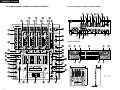 3
3
-
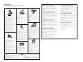 4
4
-
 5
5
-
 6
6
-
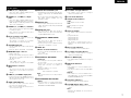 7
7
-
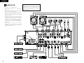 8
8
-
 9
9
-
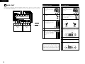 10
10
-
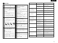 11
11
-
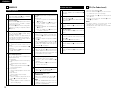 12
12
-
 13
13
-
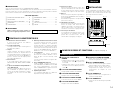 14
14
-
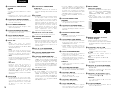 15
15
-
 16
16
-
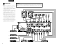 17
17
-
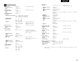 18
18
-
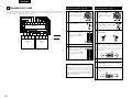 19
19
-
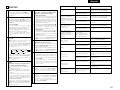 20
20
-
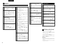 21
21
-
 22
22
-
 23
23


Denon DN-X1500 Manuale utente
- Categoria
- Mixer audio
- Tipo
- Manuale utente
- Questo manuale è adatto anche per
in altre lingue
- English: Denon DN-X1500 User manual
- français: Denon DN-X1500 Manuel utilisateur
Documenti correlati
Altri documenti
-
Denon DJ X1850 Prime Professional 4-Channel DJ Club Mixer Manuale utente
-
DJ-Tech DJM-303 Manuale utente
-
Denon DJ DN-X1700 Manuale utente
-
Ask Proxima S3000 Series Istruzioni per l'uso
-
-
Pioneer DJM-707 Manuale del proprietario
-
Tascam X-15, X-17 Manuale del proprietario
-
-
Pioneer DJ Equipment DJM-2000 Manuale utente
-