
http://www.tyan.com
1
Thunder n3600S
///
S2933
Version 1.0
Copyright
Copyright © TYAN Computer Corporation, 2007. All rights reserved. No part of
this manual may be reproduced or translated without prior written consent from
TYAN Computer Corp.
Trademark
All registered and unregistered trademarks and company names contained in
this manual are property of their respective owners including, but not limited to
the following.
TYAN, Thunder n3600S are trademarks of TYAN Computer Corporation.
AMD, Opteron, and combinations thereof are trademarks of AMD Corporation.
AMI, AMI BIOS are trademarks of AMI Technologies.
Microsoft, Windows are trademarks of Microsoft Corporation.
SuSE,is a trademark of SuSE AG.
Marvell
®
is a trademark of Broadcom Corporation and/or its subsidiaries
XGI and XG20 are trademarks of XGI Corporation
nVIDIA, nForce are trademarks of NVIDIA Corporation.
Notice
Information contained in this document is furnished by TYAN Computer
Corporation and has been reviewed for accuracy and reliability prior to printing.
TYAN assumes no liability whatsoever, and disclaims any express or implied
warranty, relating to sale and/or use of TYAN products including liability or
warranties relating to fitness for a particular purpose or merchantability. TYAN
retains the right to make changes to product descriptions and/or specifications
at any time, without notice. In no event will TYAN be held liable for any direct or
indirect, incidental or consequential damage, loss of use, loss of data or other
malady resulting from errors or inaccuracies of information contained in this
document.

http://www.tyan.com
2
Table of Contents
Chapter 1: Introduction
1.1 Congratulations Page 5
1.2 Hardware Specifications Page 5
Chapter 2: Board Installation
2.1 Board Image Page 8
2.2 Block Diagram Page 9
2.3 Board Parts, Jumpers and Connectors Page 10
2.4 Tips on Installing Motherboard in Chassis Page 20
2.5 Installing the Processor(s) Page 21
2.6 Installing the Memory Page 24
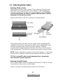
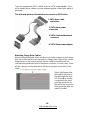
2.7 Attaching Drive Cables Page 27
2.8 Installing Add-In Cards Page 29
2.10 Connecting External Devices Page 30
2.11 Installing the Power Supply Page 31
2.12 Finishing Up Page 32
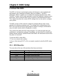
Chapter 3: BIOS Setup
3.1 About the BIOS Page 33
3.2 BIOS Main Menu Page 35
3.3 Advanced Menu Page 36
3.4 PCI/PnP Menu Page 58
3.5 Boot Menu Page 60
3.6 Security Menu Page 67
3.7 Chipset Menu Page 68
3.8 Exit Menu Page 75
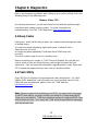
Chapter 4: Diagnostics
4.1 Beep Codes Page 77
4.2 Flash Utility Page 77
4.3 AMIBIOS Post Code Page 78
Appendix: SMDC Information Page 81
Glossary Page 83
Technical Support Page 89

http://www.tyan.com
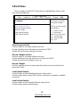
3
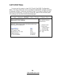
Check the box contents!
1x Thunder n3600S S2933G2NR motherboard
1x 34-Pin floppy drive cable
4 x SATA cable
2 x SATA Drive Power Adapter
1 x Ultra-DMA-100/66 IDE cable
1 x USB2.0 cable
1 x Thunder n3600S user’s manual
1 x Thunder n3600S Quick Reference guide
1 x TYAN driver CD
1 x I/O shield
2 x CPU Retention Frame and Back Plate
If any of these items are missing, please contact your vendor/dealer for
replacement before continuing with the installation process.

http://www.tyan.com
4
NOTE

http://www.tyan.com
5
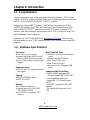
Chapter 1: Introduction
1.1 - Congratulations
You have purchased one of the most powerful server solutions. The Thunder
n3600S (S2933) is a flexible AMD64 platform for multiple applications, based on
NVIDIA nForce Pro3600 and SMSC SCH5017 chipsets.
Designed to support AMD
®
Opteron™ 2000 series processors and DDRII-
667/533/400 memory, the S2933 with integrated Dual Gigabit Ethernet LAN,
built-in 16MB XGI XG20
TM
video and four serial ATA ports, is ideal for CPU,
memory, and video intensive applications such as CAD, Graphics Design, and
High Bandwidth Video Editing, etc.
Remember to visit TYAN’s Website at http://www.TYAN.com
. There you can
find information on all of TYAN’s products with FAQs, online manuals and BIOS
upgrades.
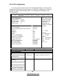
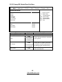
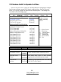
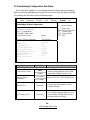
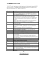
1.2 - Hardware Specifications
Processor
•Dual 1207-pin ZIF sockets
•Supports up to two AMD Socket F
Opteron 2000 series processors
•Up to 1.0GHz Hyper-Transport link
support
Expansion Slots
•One (1) x16 PCI Express slot with
x16 signal
Chipset
•nVIDIA NFP3600 chipset
•SMSC SCH5017
Memory
•Dual memory channels
•Supports up to 8x (4+4) DDR2
667/533/400 DIMMs
•Up to 32GB of registered, ECC
memory
Back Panel I/O Ports
•Stacked PS/2 mouse & keyboard
ports
•Stacked two USB2.0 ports
•One 9-pin COM1 port
•One 15-pin VGA port
•Stacked two RJ-45 gigabit LAN
ports
Integrated LAN Controllers
•Two NFP3600 integrated MAC
with two Marvell 88E1116 single
port Gigabit Ethernet PHY
- Integrated TCP offload Engine
(TOE)
- IEEE802.3 compliant, WOL/PXE
support
- Pin header for front panel LAN
LED

http://www.tyan.com
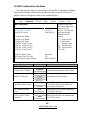
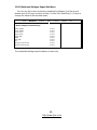
6
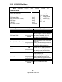
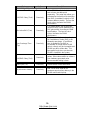
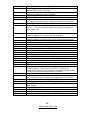
System Management
•SMSC SCH5017 w/ 2x
EMC6D103
•2x CPU fAN & 8x 4-pin system fan
headers, with tachometer input
and auto fan control
•Temperature and voltage
monitoring
•Watchdog timer
•Port 80 code display LED
Integrated PCI IDE
•One ATA IDE slot for two IDE
devices
•Support for ATA-133/100/66/33
IDE drives and ATAPI compliant
devices
Integrated 2D/3D PCI Graphics
•XGI Volari Z7 (XG20)
•16MB frame buffer memory
Integrated Serial ATA II
•Supports up to 4 Serial ATA ports
running at 3.0Gb/s
•Serial ATA II specification
compliant
•nVIDIA MediaShield
TM
RAID
supports for RAID 0, 1, 0+1, 5,
JBOD
•HDD LED connector
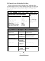
Server Management
•TYAN M3291, IPMI 2.0 Remote
System Mgmt card
•Renesas H8S2167 BMC controller
•BT, KCS, Logging support
•IPMI-over-LAN
•Remote power on/off and reset
Integrated I/O Interface
•One floppy connector (right angle)
•Four SATA ports
•One IDE connector (right angle)
•Two USB 2.0 ports (via cable)
•Front panel 2x14 pin 2.0mm pitch
header
•TYFP1 TYAN 2x9 pin header
•TYFP2 TYAN 2x6 pin header
•One 2x7 pin 2.0mm pitch FAN
•header
•TYAN 6-pin LCM header
•2x25 IPMI pin header for TYAN
SMDC
BIOS
•AMI BIOS 8Mbit Flash
•Supports ACPI 2.0
•PnP, DMI2.0, WfM 2.0 power
management
Power
•EPS12V (24-pin+8-pin+4-pin)
power connectors
•One 4-pin power connector for
HDD (right angle)
•8 layers PCB
MB Form Factor
•265mm x 240mm for TYANGT14
1U chassis
Regulatory
•FCC Class B (Declaration of
Conformity)
•CE (Declaration of Conformity)
SKU
•S2933G2NR-BP

http://www.tyan.com
7
Chapter 2: Board Installation
You are now ready to install your motherboard. The mounting hole pattern of
the Thunder n3600S S2933 matches the ATX specification. Before continuing
with installation, confirm that your chassis supports an ATX motherboard.
How to install our products right… the first time
The first thing you should do is reading this user’s manual. It contains important
information that will make configuration and setup much easier. Here are some
precautions you should take when installing your motherboard:
(1) Ground yourself properly before removing your motherboard from the
antistatic bag. Unplug the power from your computer power supply and
then touch a safely grounded object to release static charge (i.e. power
supply case). For the safest conditions, TYAN recommends wearing a
static safety wrist strap.
(2) Hold the motherboard by its edges and do not touch the bottom of the
board, or flex the board in any way.
(3) Avoid touching the motherboard components, IC chips, connectors,
memory modules, and leads.
(4) Place the motherboard on a grounded antistatic surface or on the
antistatic bag that the board was shipped in.
(5) Inspect the board for damage.
The following pages include details on how to install your motherboard into your
chassis, as well as installing the processor, memory, disk drives and cables.
NOTE
DO NOT APPLY POWER TO THE BOARD IF IT HAS BEEN
DAMAGED

http://www.tyan.com
8
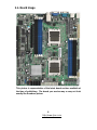
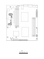
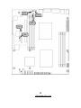
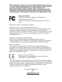
2.1- Board Image
This picture is representative of the latest board revision available at
the time of publishing. The board you receive may or may not look
exactly like the above picture.

http://www.tyan.com
9
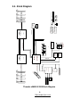
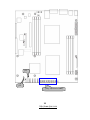
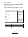
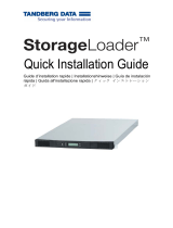
2.2 - Block Diagram
Thunder n3600S S2933 Block Diagram
FAN8
FAN7FAN5 FAN6
FDD R/A
J25 J23J24 J22
SATA3
SATA2
SATA1
FDD
SATA4
USB2.0 x 1 front
panel headers
SMSC SCH5017
Marvell
J12
Marvell
88E1116
GBLAN1
U2
GBLAN2
88E1116
U4
USB1
RGMII BUS
RGMII BUS
USB2.0 port X 2
rear panel
J4
PCIEX16 BUS
J14J13J12J11J17
U52
U8
J6
U29
U22
U44
16MB RAM
U63
FAN4FAN3
EIDE (ATA/133) x1 R/A
U21
PCI32 BUS
AMD
Socket F
NVIDIA
VGA
16x16 HyperTransport OUT
LPC ROM
011010001000
LINK 1
LINK 1
I N
PS/2 Keyboard & Mouse
SMSC 6D103
I N
OUT
Serial Port I/O Port
LPC Super I/O
XG20
Hardware monitor
SMSC 6D103
LINK 0
LPC BUS
NFP3600
SMDC Interface
IDE1
FAN2
Hardware monitor
U42
FAN1
100 101
240 pin
DIMM0
533-667MHz
J16
100
J17
16x16 HyperTransport
J17
100
240 pin
DIMM0
240 pin
DIMM3
240 pin
DIMM2
240 pin
DIMM1
240 pin
DIMM3
240 pin
DIMM2
240 pin
DIMM1
533-667MHz
Socket F
CPU0
AMD
CPU1

http://www.tyan.com
10
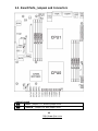
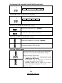
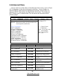
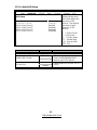
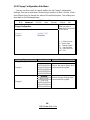
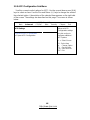
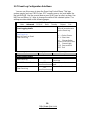
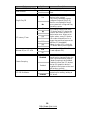
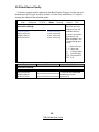
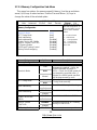
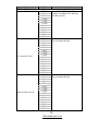
2.3 - Board Parts, Jumpers and Connectors
Jumper Legend
OPEN - Jumper OFF, without jumper cover
CLOSED – Jumper ON, with jumper cover

http://www.tyan.com
11
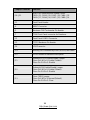
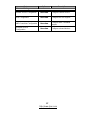
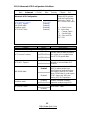
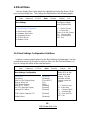
Jumper/Connector Function
J14~J21
4-pin Fan Connectors with Speed Control
FAN1: J21, FAN2: J20, FAN3: J19, FAN4: J18
FAN5: J17, FAN6: J16, FAN7: J15, FAN8: J14
J11 Front Panel Header
J6 SMDC Connector
J5 Barebone FAN Tachometer Pin Header
J7 TYAN Front Panel connector for Barebone
J12 Front Panel USB2.0 Connector
J13 TYFP2 Barebone Pin Header
J26 LCM Connector
JP4 Warning LED controlled by SMDC(M3291) with cable
JP5 IDLED header for Barebone front panel
JP1
Onboard ID LED Enable/Disable Jumper
Close Pin1 & Pin 2: Enable (Default)
Close Pin 2 & Pin 3: Disable
JP2
Onboard VGA Enable/Disable Jumper
Close Pin1 & Pin 2: Enable (Default)
Close Pin 2 & Pin 3: Disable
JP3
Clear CMOS Jumper
Close Pin1 & Pin 2: Normal (Default)
Close Pin 2 & Pin 3: Clear

http://www.tyan.com
12
J14~J21
(
FAN1~FAN8
)
J11
J12

http://www.tyan.com
13
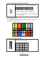
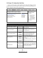
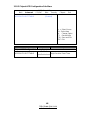
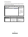
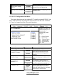
J14~J21: 4-pin FAN Connectors with speed control
1
Use these headers to connect the cooling fans to your
motherboard to keep the system stable and reliable.
Pin 1 Pin 2 Pin 3 Pin 4
GND +12V Tachometer Speed Control
FAN1: J21, FAN2: J20, FAN3: J19, FAN4: J18
FAN5: J17, FAN6: J16, FAN7: J15, FAN8: J14
This connector supports the tachometer monitoring and
auto fan speed control.
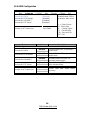
J11: Front Panel Header
The motherboard provides one front panel header for electrical connection to
the front panel switches and LED’s.
J12: Front Panel USB2.0 Connector
11 12
1
2
Use these headers to connect to the USB devices
via the enclosed USB cable.
Signal Pin Pin Signal
USBPWR 1 2 USBPWR
USB3- 3 4 USB4-
USB3+ 5 6 USB4+
GND 7 8 GND
KEY 9 10 GND
PWR LED+
PWR LED-
PWR SW#
Warning LED
KEY
GND
INTRUDER
2
4
6 8 10 12 14 16 18
1
3 5 7 9 11 13 15
17
HDD LED+
HDD LED-
Reset
NMI
+5VSB
SMBUS Data
SMBUS
Clock

http://www.tyan.com
14
J6
J5

http://www.tyan.com
15
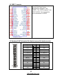
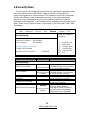
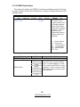
J6: SMDC Connector
The SMDC connector allows you to
connect with Tyan Server
Management Daughter Card
(SMDC). The S2933 supports Tyan
SMDC M3291. See Appendix for
more information on SMDC.
J5: Barebone FAN Tachometer Pin Header (reserved for barebone only)
1
2
28
27
Signal Pin Pin Signal
HD_LED+
1 2
HD_LED-
RST
3 4
GND
PW_LED+
5 6
GND
WARN_LED+
7 8
WARN_LED-
PCI_SMBUSDA
9 10
PCI_SMBUSCL
FP_NMI_L
11 12
GND
NMI_PWR
13 14
INTRUDER_L
PWRSW_
15 16
GND
LAN1_LED+
17 18
LAN1_LEDLINK
LAN2_LED+
19 20
LAN2_LEDLINK
NC
21 22
NC
ID_LED+
23 24
ID_LED-
IDLEDBTN-
25 26
ID_SW-
Key
27 28
NC

http://www.tyan.com
16
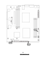
J13
J26
J7

http://www.tyan.com
17
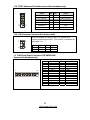
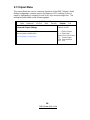
J13: TYFP2 Barebone Pin Header (reserved for barebone only)
11 12
1
2
Signal Pin Pin Signal
TP2_LAN1PW
1 2
LAN1_LEDLINK
TP2_LAN2PW
3 4
LAN2_LEDLINK
NC
5 6
GND
IDLED+
7 8
GND
IDLEDBTN-
9 10
GND
Key
11 12
NC
J26: LCM Connector (reserved for barebone only)
1
5
2
6
Use
this header to connect the LCM module with
system monitoring function. This header is reserved for
barebone use.
Pin 1 VCC Pin 2 RXD2
Pin 3 KEY Pin 4 GND
Pin 5 +5VSB Pin 6 TXD2
J7: TYAN Front Panel Connector FOR BAREBONE
(reserved for barebone only)
1
27
2
8
2
Pin 1 HD_LED+ Pin 2 HD_LED-
Pin 3 RST Pin 4 GND
Pin 5 PW_LED+ Pin 6 GND
Pin 7 WARN_LED+ Pin 8 WARN_LED-
Pin 9 PCI_SMBUSDA Pin 10 PCI_SMBUSCL
Pin 11 FP_NMI_L Pin 12 GND
Pin 13 NMI_PWR Pin 14 INTRUDER_L
Pin 15 PWRSW- Pin 16 GND
Pin 17 LAN1_LED+ Pin 18 LAN1_LEDLINK
Pin 19 LAN2_LED+ Pin 20 LAN2_LEDLINK
Pin 21 NC Pin 22 NC
Pin 23 ID_LED+ Pin 24 ID_LED-
Pin 25 IDLEDBTN- Pin 26 ID_SW-
Pin 27 KEY Pin 28 NC

http://www.tyan.com
18
JP1
JP3
JP2
JP4
JP5

http://www.tyan.com
19
JP4: Warning LED controlled by SMDC(M3291) with cable
1
This header is reserved for barebone use.
Pin 1 WLED control input Pin 2 NC
JP5: IDLED header for Barebone front panel
1
This header is reserved for barebone use.
Pin 1IDLED+Pin 2GND
JP1: Onboard ID LED Enable/Disable Jumper
1
3
Enable the onboard ID LED. (Default)
3
1
Disable the onboard ID LED function.
JP2: Onboard VGA Enable/Disable Jumper
1
3
Enable the onboard VGA function. (Default)
3
1
Disable the onboard VGA function.
JP3: Clear CMOS Jumper
1
3
Normal
(Default)
3
1
Clear
Use this jumper when you forgot your system/setup
password or need to clear system BIOS setting.
How to clear the CMOS data
- Power off system and disconnect power
supply from AC source
- Use jumper cap to close Pin_2 and 3 for
several seconds to Clear CMOS
- Replace jumper cap to close Pin_1 and 2
Reconnect power supply to AC source
Power on system

http://www.tyan.com
20
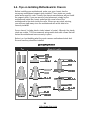
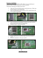
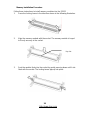
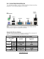
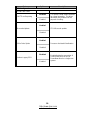
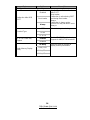
2.4 - Tips on Installing Motherboard in Chassis
Before installing your motherboard, make sure your chassis has the
necessary motherboard support studs installed. These studs are usually
metal and are gold in color. Usually, the chassis manufacturer will pre-install
the support studs. If you are unsure of stud placement, simply lay the
motherboard inside the chassis and align the screw holes of the
motherboard to the studs inside the case. If there are any studs missing,
you will know right away since the motherboard will not be able to be
securely installed.
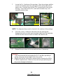
Some chassis’ include plastic studs instead of metal. Although the plastic
studs are usable, TYAN recommends using metal studs with screws that will
fasten the motherboard more securely in place.
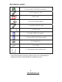
Below is a chart detailing what the most common motherboard studs look
like and how they should be installed.
La pagina si sta caricando...
La pagina si sta caricando...
La pagina si sta caricando...
La pagina si sta caricando...
La pagina si sta caricando...
La pagina si sta caricando...
La pagina si sta caricando...
La pagina si sta caricando...
La pagina si sta caricando...
La pagina si sta caricando...
La pagina si sta caricando...
La pagina si sta caricando...
La pagina si sta caricando...
La pagina si sta caricando...
La pagina si sta caricando...
La pagina si sta caricando...
La pagina si sta caricando...
La pagina si sta caricando...
La pagina si sta caricando...
La pagina si sta caricando...
La pagina si sta caricando...
La pagina si sta caricando...
La pagina si sta caricando...
La pagina si sta caricando...
La pagina si sta caricando...
La pagina si sta caricando...
La pagina si sta caricando...
La pagina si sta caricando...
La pagina si sta caricando...
La pagina si sta caricando...
La pagina si sta caricando...
La pagina si sta caricando...
La pagina si sta caricando...
La pagina si sta caricando...
La pagina si sta caricando...
La pagina si sta caricando...
La pagina si sta caricando...
La pagina si sta caricando...
La pagina si sta caricando...
La pagina si sta caricando...
La pagina si sta caricando...
La pagina si sta caricando...
La pagina si sta caricando...
La pagina si sta caricando...
La pagina si sta caricando...
La pagina si sta caricando...
La pagina si sta caricando...
La pagina si sta caricando...
La pagina si sta caricando...
La pagina si sta caricando...
La pagina si sta caricando...
La pagina si sta caricando...
La pagina si sta caricando...
La pagina si sta caricando...
La pagina si sta caricando...
La pagina si sta caricando...
La pagina si sta caricando...
La pagina si sta caricando...
La pagina si sta caricando...
La pagina si sta caricando...
La pagina si sta caricando...
La pagina si sta caricando...
La pagina si sta caricando...
La pagina si sta caricando...
La pagina si sta caricando...
La pagina si sta caricando...
La pagina si sta caricando...
La pagina si sta caricando...
La pagina si sta caricando...
La pagina si sta caricando...
-
 1
1
-
 2
2
-
 3
3
-
 4
4
-
 5
5
-
 6
6
-
 7
7
-
 8
8
-
 9
9
-
 10
10
-
 11
11
-
 12
12
-
 13
13
-
 14
14
-
 15
15
-
 16
16
-
 17
17
-
 18
18
-
 19
19
-
 20
20
-
 21
21
-
 22
22
-
 23
23
-
 24
24
-
 25
25
-
 26
26
-
 27
27
-
 28
28
-
 29
29
-
 30
30
-
 31
31
-
 32
32
-
 33
33
-
 34
34
-
 35
35
-
 36
36
-
 37
37
-
 38
38
-
 39
39
-
 40
40
-
 41
41
-
 42
42
-
 43
43
-
 44
44
-
 45
45
-
 46
46
-
 47
47
-
 48
48
-
 49
49
-
 50
50
-
 51
51
-
 52
52
-
 53
53
-
 54
54
-
 55
55
-
 56
56
-
 57
57
-
 58
58
-
 59
59
-
 60
60
-
 61
61
-
 62
62
-
 63
63
-
 64
64
-
 65
65
-
 66
66
-
 67
67
-
 68
68
-
 69
69
-
 70
70
-
 71
71
-
 72
72
-
 73
73
-
 74
74
-
 75
75
-
 76
76
-
 77
77
-
 78
78
-
 79
79
-
 80
80
-
 81
81
-
 82
82
-
 83
83
-
 84
84
-
 85
85
-
 86
86
-
 87
87
-
 88
88
-
 89
89
-
 90
90


Tyan S2933 Manuale utente
- Tipo
- Manuale utente
- Questo manuale è adatto anche per
in altre lingue
- English: Tyan S2933 User manual
Documenti correlati
-
Tyan S2881 Manuale utente
-
-
-
-
-
-
-
-
-
Altri documenti
-
Gamdias AEOLUS M2-1205R Manuale utente
-
Gamdias AEOLUS M1 1205R Manuale utente
-
ESD I.2306.08 Manuale del proprietario
-
Nvidia JETSON TX1 Quick Start Manuals
-
Approx appPCI4PV2 Guida utente
-
Motorola SDC1000 Istruzioni per l'uso
-
Multitech IAC-F696 Manuale utente
-
 TANDBERG StorageLoader LTO-6 Quick Installation Guide
-
AKO H 290 S Assembly and Operating Instructions
