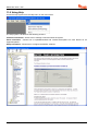
Pyronix Matrix 832 Guida d'installazione
- Categoria
- Antincendio
- Tipo
- Guida d'installazione
Questo manuale è adatto anche per

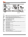
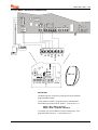
Matrix Installation Guide
This Guide Supports the Following Panels:
MATRIX 832
MATRIX 832+
MATRIX 424
RINS428-5
Tel: +44(0) 1709 700100

Pyronix Association of Security Specialists
Installer Support
The Pyronix Association of Security specialists has been developed with the focus on what you the installer
would like to see from one of the leading manufactures of security equipment.
The philosophy behind the association is that you will receive tangible benefits, which are applicable to both
the work and home environment.
The Association Awards Catalogue
By collecting the tokens which are printed on the packaging you can redeem against gift vouchers for Argos,
Marks & Spencer and Whitbread Leisure.
Product Consultation
Product training and consultation evenings are provided up and down the country.
To join PASS please contact our marketing department:
Tel: +44 (0)1709 700100
technical.support@pyronix.com
As a new member of PASS you will be issued with a free technical support telephone number.

Matrix 832 / 832+ / 424
RINS428-5 Page i
Contents
SECTION 1: TECHNICAL SPECIFICATIONS & SYSTEM OVERVIEW ..............................1
1.1 Technical Specifications........................................................................................................1
1.1.1 Main Control Panel............................................................................................................................1
1.1.2 Additional Expanders ........................................................................................................................3
1.2 Battery Capacity Calculations...............................................................................................4
1.2.1 UK Requirements..............................................................................................................................4
1.2.2 Norwegian & Danish Requirements..................................................................................................4
1.2.3 Swedish Requirements .....................................................................................................................4
1.3 System Overview....................................................................................................................5
SECTION 2: SAFETY & APPROVALS ................................................................................9
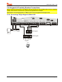
SECTION 3: MOUNTING PROCEDURE............................................................................14
3.1 Mounting Procedure for Matrix – Plastic & Metal Case ....................................................14
3.2 Panel Layout – Plastic Case ................................................................................................14
3.3 Panel Layout – Metal Case ..................................................................................................15
3.4 Battery Installation Procedure ............................................................................................15
SECTION 4: CABLING RULES FOR THE MATRIX BUS..................................................16
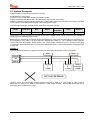
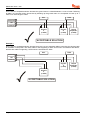
4.1 System Examples .................................................................................................................17
SECTION 5: OPERATING MODES....................................................................................19
5.1 Disarmed Mode.....................................................................................................................19
5.2 Armed Mode..........................................................................................................................19
5.3 Arm Mode ..............................................................................................................................19
5.4 Entry / Exit Mode ..................................................................................................................19
5.5 Alarm Mode ...........................................................................................................................19
5.6 Anti-Code Reset....................................................................................................................19
5.7 First to Alarm Mode..............................................................................................................20
5.8 Engineer Mode......................................................................................................................20
5.9 User Mode .............................................................................................................................20
SECTION 6: KEYPAD/READER SYMBOLS & INDICATIONS..........................................21
6.1 The ICON Keypad .................................................................................................................21
6.2 The LCD Keypad...................................................................................................................22
6.3 The Proximity Reader...........................................................................................................22
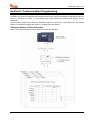
SECTION 7: PROGRAMMING THE SYSTEM ...................................................................23
7.1 Addressing the LCD & ICON Keypads ...............................................................................23
7.2 Addressing the Proximity Reader.......................................................................................24
7.2.1 Connection of MX PROX to a PC ...................................................................................................24
7.3 Finding Bus Devices ............................................................................................................25
7.4 Factory Default Settings of Matrix System ........................................................................25
7.4.1 Engineer Code ................................................................................................................................25
7.4.2 Global System Options ...................................................................................................................25
7.4.3 Zone Types, Zone Attributes & Zone Settings................................................................................26
7.4.4 User Codes, User Code Attributes & Proximity Card Allocation.....................................................27
7.4.5 Keypads & Proximity Readers Partition Allocation .........................................................................27
7.4.6 System & Tamper Faults Partition Allocation..................................................................................27
7.4.7 Partition Options..............................................................................................................................27
7.4.8 Arm Options ....................................................................................................................................27
7.4.9 System Timers ................................................................................................................................28
7.4.10 Programmable Outputs.................................................................................................................28
7.4.11 Digital Communicator....................................................................................................................29
7.4.12 Communication Formats...............................................................................................................29
7.4.13 Events Reporting...........................................................................................................................29
7.4.14 DD243 Option Defaults .................................................................................................................30
7.4.15 Confirmation Timer Defaults .........................................................................................................30
7.4.16 Zone Mapping Defaults.................................................................................................................31

Matrix 832 / 832+ / 424
Page ii RINS428-5
7.5 Entering / Exiting Engineer Mode .......................................................................................32
7.5.1 Entering Engineer Mode................................................................................................................. 32
7.5.2 Exiting Engineer Mode ................................................................................................................... 32
7.5.3 Changing Engineer Code............................................................................................................... 32
7.6 Global System Options ........................................................................................................33
7.6.1 System Options 1 ........................................................................................................................... 39
7.6.2 System Options 2 ........................................................................................................................... 39
7.6.3 System Options 3 ........................................................................................................................... 39
7.7 Zone Types, Configuration, Attributes & Partition Allocation..........................................40
7.7.1 Zone Types..................................................................................................................................... 44
7.7.2 Zone Configuration......................................................................................................................... 44
7.7.3 Zone Names Programming from LCD Keypad .............................................................................. 47
7.7.4 Key Map Tables.............................................................................................................................. 48
7.8 User Codes & User Attributes .............................................................................................49
7.8.1 Programming User Codes.............................................................................................................. 52
7.8.2 User Code Partition Allocation ....................................................................................................... 52
7.8.3 User Code Attributes Allocation ..................................................................................................... 52
7.8.4 Temporary Code............................................................................................................................. 52
7.8.5 Assigning / Clearing Proximity Card to / from User Code .............................................................. 52
7.9 Keypads & Proximity Readers Partition Allocation...........................................................53
7.9.1 Icon Keypad Programming............................................................................................................. 55
7.9.2 LCD Keypad Programming ............................................................................................................ 55
7.9.3 Proximity Reader Programming ..................................................................................................... 58
7.9.4 Changing Default Language on LCD Keypad................................................................................ 58
7.10 System Faults & Tamper Alarms Warning Allocation .....................................................59
7.10.1 System Faults (Warning Partition Allocation)............................................................................... 59
7.10.2 Bell And Tamper Faults (Warning Partition Allocation)................................................................ 59
7.11 Partition Options.................................................................................................................60
7.11.1 Partition Options 1........................................................................................................................ 62
7.11.2 Partition Options 2........................................................................................................................ 63
7.12 Arm Options ........................................................................................................................63
7.12.1 Exit Terminator Type for Arm Mode A.......................................................................................... 65
7.12.2 Exit Terminator Type for Arm Mode B.......................................................................................... 65
7.12.3 Exit Terminator Type for Arm Mode C ......................................................................................... 66
7.12.4 Exit Terminator Type for Arm Mode D ......................................................................................... 66
7.12.5 Home & Away Allocation .............................................................................................................. 66
7.12.6 Partition Dependency ................................................................................................................... 66
7.12.7 Keyswitch Zone Arm Mode Allocation.......................................................................................... 67
7.12.8 Number of Rearms ....................................................................................................................... 67
7.13 System Timers ....................................................................................................................68
7.13.1 Bell Time....................................................................................................................................... 70
7.13.2 Bell Time Delay ............................................................................................................................ 70
7.13.3 Entry Time .................................................................................................................................... 70
7.13.4 Exit Time....................................................................................................................................... 70
7.13.5 Final Exit Delay............................................................................................................................. 70
7.13.6 Auto-Arm Commencing Time – Every Day .................................................................................. 70
7.13.7 Inactivity Auto-Arm ....................................................................................................................... 70
7.13.8 AC Fail Warning & Report Delay.................................................................................................. 70
7.13.9 Telephone Line Fail Warning & Report Delay.............................................................................. 70
7.13.10 Seconds in Last Minute of the Day ............................................................................................ 70
7.14 Programmable Outputs......................................................................................................71
7.14.1 PGM Programming....................................................................................................................... 74
7.14.2 Zone to Follow in Partition............................................................................................................ 74
SECTION 8: COMMUNICATION PROGRAMMING .......................................................... 75
8.1 Digital Communicator ..........................................................................................................76
8.1.2 Account Codes & Account Partition Allocation............................................................................... 78
8.1.3 Up / Down Loading Access Code................................................................................................... 78
8.1.4 Digital Communicator Options 1..................................................................................................... 78
8.1.5 Digital Communicator Options 2..................................................................................................... 78
8.1.6 Test Dial Time ................................................................................................................................ 78
8.1.7 Test Dial Interval ............................................................................................................................ 78
8.1.8 Telephone Number 1 Allocation..................................................................................................... 78

Matrix 832 / 832+ / 424
RINS428-5 Page iii
8.1.9 Telephone Number 2 Allocation......................................................................................................78
8.1.10 Telephone Number 3 Allocation....................................................................................................79
8.1.11 Test Dial Sequence (Group Reporting).........................................................................................79
8.1.12 Anti-Code Algorithm Number ........................................................................................................79
8.2 Reporting Formats ...............................................................................................................79
8.2.1 Telephone Number Programming & Format Allocation ..................................................................82
8.2.2 BSIA Format Channel Map .............................................................................................................83
8.3 Send Options & Group Reporting Sequence.....................................................................83
8.3.1 Disarmed Mode Events Send Options............................................................................................85
8.3.2 Arm Mode A Events Send Options .................................................................................................85
8.3.3 Arm Mode B Events Send Options .................................................................................................85
8.3.4 Arm Mode C Events Send Options .................................................................................................86
8.3.5 Arm Mode D Events Send Options .................................................................................................86
8.3.6 Restoral Events Send Options........................................................................................................86
8.3.7 Allocating Telephone Numbers to Alarm Types in Partitions..........................................................87
8.3.8 MX Voice Module Support ..............................................................................................................87
8.3.9 Change Number of Voice Dials.......................................................................................................87
SECTION 9: INSTALLING DD243......................................................................................88
9.2 Zone Mapping .......................................................................................................................88
9.3 Means of Setting (Arming) and Unsetting (Disarming).....................................................88
9.4 Resetting Following an Alarm Condition ........................................................................... 89
9.5 Mis-Operation Signals..........................................................................................................89
9.6 DD243 Options Table ...........................................................................................................90
9.7 DD243 Options 1...................................................................................................................92
9.8 DD243 Zone Map...................................................................................................................92
9.9 DD243 Partition Confirmation Times .................................................................................. 92
SECTION 10: EVENTS MEMORY LOG & SYSTEM MAINTENANCE ..............................93
10.1 Reading The Event Log......................................................................................................93
10.1.2 Viewing Event Log Memory ..........................................................................................................94
10.2 System Faults & Maintenance........................................................................................... 99
10.2.1 NVM Reset to Factory Default ......................................................................................................99
10.2.2 Programmable Outputs Test.........................................................................................................99
10.2.3 Walk Test ......................................................................................................................................99
10.2.4 Scan for Devices on the Bus.........................................................................................................99
10.2.5 Local Up / Down Loading Session (RS232)................................................................................100
10.2.6 Engineer Code NVM Reset to Factory Default ...........................................................................100
10.2.7 Programmable Outputs Test.......................................................................................................100
10.2.8 Walk Test ....................................................................................................................................100
10.2.9 Scan For Devices On the Bus.....................................................................................................100
10.2.10 Local Up / Down Loading using RS232 Output ........................................................................100
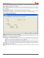
SECTION 11: UDL PC SOFTWARE DATA MANAGEMENT...........................................101
11.1 Customer Explorer ...........................................................................................................101
11.2 Editing Customer Information......................................................................................... 103
11.2.1 Global Information.......................................................................................................................104
11.2.2 Principal Contact .........................................................................................................................104
11.2.3 Keyholders ..................................................................................................................................104
11.2.4 Partition Information....................................................................................................................104
11.3 Exporting and Importing Customers .............................................................................. 105
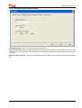
11.4 Entering Panel Details & Uploading/Downloading to the Panel...................................106
11.4.1 Default Records ..........................................................................................................................107
11.4.2 Normal Dial to the Panel .............................................................................................................108
11.4.3 AMC Dial to the Panel.................................................................................................................108
11.4.4 Local Connection ........................................................................................................................109
11.4.5 Dial Back .....................................................................................................................................109
11.4.6 Sending Data to a Panel .............................................................................................................109
11.4.7 Getting Data from a Panel...........................................................................................................109
11.4.8 Verifying Panel Details................................................................................................................109
11.4.9 12.4.9 Online Panel Information .................................................................................................110

Matrix 832 / 832+ / 424
Page iv RINS428-5
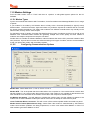
11.5 Modem Settings ................................................................................................................111
11.5.1 Modem Types............................................................................................................................. 111
11.5.2 Configuring Communications Options........................................................................................ 111
11.5.3 Configuring Dial Options ............................................................................................................ 112
11.5.4 Configuring Dial Back Options ................................................................................................... 113
11.5.5 Configuring Computer Network Options .................................................................................... 114
11.5.6 Character Set Options................................................................................................................ 115
11.5.7 Customer Map............................................................................................................................ 116
11.5.8 Configuring Other Options.......................................................................................................... 117
11.6 Using Help .........................................................................................................................118
SECTION 12: INSTALLATION, SERVICE & MAINTENANCE........................................ 119
12.1 Scanning for Devices .......................................................................................................120
12.2 Matrix 832 PCB..................................................................................................................123
12.3 Matrix 832+ PCB................................................................................................................124
12.4 Matrix 424 PCB..................................................................................................................125
12.5 Matrix Voice Module .........................................................................................................126
12.5.1 Programming the Voice Module................................................................................................. 126
12.5.1 Voice Module Connections to Matrix 832+................................................................................. 127
12.6 MX-BATT Battery Monitor Board.....................................................................................128
12.7 Matrix Zone Expanders ....................................................................................................129
12.7.1 Local Plug-On 8 Zone Expander................................................................................................ 129
12.7.2 MX-RIX with Zone Analyser ....................................................................................................... 131
12.8 Matrix PGM Expanders.....................................................................................................136
12.8.1 MX-ROX8R/8T Connections to 832 ........................................................................................... 137
12.8.2 MX-ROX8R/8T Connections to 832+......................................................................................... 138
12.9 Keypads & Proximity Readers Connections..................................................................139
12.9.1 Connecting a Single Keypad to Matrix 832................................................................................ 139
12.9.2 Connecting a Single Keypad to Matrix 832 +............................................................................. 140
12.9.3 Connecting Multiple Keypads to a Matrix 832 – Daisy Chain .................................................... 141
12.9.4 Connecting Multiple Keypads to a Matrix 832 – Star Configuration........................................... 142
12.9.5 Connecting Proximity Readers to a Matrix 832.......................................................................... 142
12.9.6 Connecting Proximity Readers to a Matrix 832+........................................................................ 143
12.10 Connecting a Matrix to a Telephone Line.....................................................................143
12.11 Zone Wiring Diagrams....................................................................................................144
12.11.1 Zone Doubling to Matrix 832 .................................................................................................... 144
12.11.2 Zone Doubling to Matrix 832+ .................................................................................................. 145
12.11.3 Zone Doubling to Matrix 424 .................................................................................................... 146
12.11.4 Normally Closed Zones to Matrix 832 ...................................................................................... 147
12.11.5 Double End of Line Resistors to Matrix 832............................................................................. 147
12.11.6 Double End of Line Resistors to Matrix 832+........................................................................... 148
12.12 Programmable Outputs Connections ...........................................................................149
12.12.1 Belle Connection to Matrix 832 ................................................................................................ 149
12.12.2 Belle Connection to Matrix 832+ .............................................................................................. 150
12.12.3 Belle Connection to Matrix 424 ................................................................................................ 151
12.12.4 Decibell Connection to Matrix 832 ........................................................................................... 152
12.12.5 Decibell Connection to Matrix 424 ........................................................................................... 152
12.12.6 Twin Alert Connection to Matrix 832 ........................................................................................ 153
12.12.7 Twin Alert Connection to Matrix 832+ ...................................................................................... 154
12.12.8 Twin Alert Connection to Matrix 424 ........................................................................................ 155
12.12.9 Vocaliser Connection to Matrix 832 ......................................................................................... 155
12.12.10 Vocaliser Connection to Matrix 832+ ..................................................................................... 156
12.12.11 Two Wire Fire Detector Connection to Matrix 832 ................................................................. 157
12.12.12 Normally Open Four Wire Fire Detector Connection to Matrix 832 ....................................... 157
12.12.13 Buzzer, LED & any Siren Connection to PGM on Matrix 832................................................ 158
12.12.14 High-Powered Siren Connections for Matrix 832 / 832+ / 424............................................... 158
SECTION 13: PARTITION MANAGEMENT .................................................................... 159
13.1 Example 1 ..........................................................................................................................159
13.2 Example 2 ..........................................................................................................................160
SECTION 14: ENGINEER QUICK PROGRAMMING GUIDE .......................................... 161

! Matrix 832 / 832+ / 424
RINS428-5 Page 1
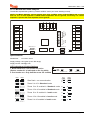
Section 1: Technical Specifications & System Overview
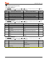
1.1 Technical Specifications
1.1.1 Main Control Panel
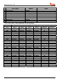
Matrix 832+ Matrix 832 Matrix 424
ZONES
Zone Loop Current
0.54mA - Max 0.54mA - Max 0.54mA - Max
Zone Activation Resistance
DEOL
Short circuit
<800Ω <800Ω <800Ω
Normal
>800Ω to <6kΩ >800Ω to <6kΩ >800Ω to <6kΩ
Activated
>6kΩ to <36kΩ >6kΩ to <36kΩ >6kΩ to <36kΩ
Open circuit
>36kΩ >36kΩ >36kΩ
Normally Closed
Normal
<4kΩ <4kΩ <4kΩ
Activated
>4kΩ >4kΩ >4kΩ
Doubled
Both zones Normal
>2kΩ to <6kΩ >2kΩ to <6kΩ >2kΩ to <6kΩ
Both zones Activated
>11kΩ to <35kΩ >11kΩ to <35kΩ >11kΩ to <35kΩ
Zone n Activated
>8kΩ to <11kΩ >8kΩ to <11kΩ >8kΩ to <11kΩ
Zone n+16 Activated
>6kΩ to <8kΩ >6kΩ to <8kΩ >6kΩ to <8kΩ
Zone Doubled: Tamper
Activated
<2kΩ or >35kΩ <2kΩ or >35kΩ <2kΩ or >35kΩ
Zone Response Time
Standard Zones
350ms 350ms 350ms
Fast Zones
100 ms 100 ms 100 ms
Only Zone 1 Fast
Zone1 - 30ms
Other zones - 350ms
Zone1 - 30ms
Other zones - 350ms
Zone1 - 30ms
Other zones - 350ms
Zone Protection
18V Varister 18V Varister N/A
PROGRAMMABLE OUTPUTS (PGM)
PGM 1
Relay contacts
30V@3A
Relay contacts
30V@3A
Relay contacts
30V@3A
PGM 2
Relay contacts
30V@3A
Open Collector
12V@200mA
Open Collector
12V@200mA
PGM 3
Open Collector
12V@200mA
Open Collector
12V@ 200mA
Open Collector
12V@200mA
PGM 4
Open Collector
12V@10mA
Open Collector
12V@10mA
Open Collector
12V@10mA
DIGITAL COMMUNICATOR
Telephone Line Monitoring
Yes Yes Yes
Digital Communicator
Analogue Line Analogue Line Analogue Line
Lightning Protection
Heavy duty protection
6.75kV / 125A
Heavy duty protection
6.75kV / 125A
Heavy duty protection
6.75kV / 125A
POWER SUPPLY
Power Input
17Vac 17Vac 17Vac
Transformer Rating
44VA (Metal case)
21VA (Plastic case)
21VA 21VA
EN50131-6 Type
A A A
Voltage Output
13.6Vdc@1A regulated
Max 13.8V Min 10.5V
13.6Vdc@1A regulated
Max 13.8V Min 10.5V
13.6Vdc@1A regulated
Max 13.8V Min 10.5V
Ripple
1% Max. 1% Max 1% Max
Total Current Output
AUX, Bell, K+
600mA (Plastic)
1.1A (Metal)
600mA 600mA
Panel Current Requirement
200mA 200mA 200mA

Matrix 832 / 832+ / 424
Page 2 RINS428-5
Matrix 832+ Matrix 832 Matrix 424
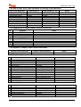
FUSES
Bell fuse
Quick blow 1A – F1L Quick blow 1A – F1L Quick blow 1A – F1L
Aux fuse
Quick blow 1A – F1L Quick blow 1A – F1L N/A
Keypad fuse
Quick blow 1A – F1L N/A N/A
Battery fuse
Slow blow 5A – T5H N/A N/A
BATTERY
Type
12V Lead acid
rechargeable
12V Lead acid
rechargeable
12V Lead acid
rechargeable
Battery Charge
Min 6V Min 6V Min 6V
Maximum Battery Charge
Current
800mA (Metal Case)
350mA (Plastic case)
350mA 350mA
Battery Charge Method
The Matrix panel monitors the voltage of the battery and commences
charging when the battery reaches 12.8V +/- 5% and disables charging
when it reaches 13.6V +/- 5%.
Battery Capacity
Metal Enclosure
2.8 to 17Ah
Plastic Enclosure
2.8 to 7Ah
Plastic Enclosure
2.8 to 7Ah
Plastic Enclosure
2.8 to 7Ah
BAT Terminal Protection
Short circuit & battery
reverse protection.
Short circuit & battery
reverse protection.
Short circuit & battery
reverse protection.
Low Battery Detect Level
10.7V +/- 0.2V 10.7V +/- 0.2V 10.7V +/- 0.2V
Battery Cutoff Level
10.4V +/- 0.2V
(With MX-BATT)
10.4V +/- 0.2V
(With MX-BATT)
10.4V +/- 0.2V
(With MX-BATT)
MECHNICAL
Security Grade
2 (Metal Case)
N/A (Plastic Case)
N/A N/A
Environmental Class
2 (Metal Case)
N/A (Plastic Case)
N/A N/A
Dimensions
Plastic
340 x 280 x 94.5 mm 340 x 280 x 94.5 mm 340 x 280 x 94.5 mm
Metal
389.5 x 314.5 x
96.2mm
N/A N/A
TEMPERATURE
Operational Metal Case
-10 to +55ºC
14 to 131ºF
Plastic Case
0 to +40ºC
32 to 104ºF
0 to +40ºC
32 to 104ºF
0 to +40ºC
32 to 104ºF
Storage
-20 to +60ºC
-4 to 172ºF
-20 to +60ºC
-4 to 172ºF
-20 to +60ºC
-4 to 172ºF
Maximum Humidity
93% Rh (Metal Case) N/A N/A

! Matrix 832 / 832+ / 424
RINS428-5 Page 3
1.1.2 Additional Expanders
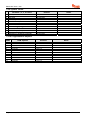
PROGRAMMABLE OUTPUT EXPANDERS
TRANSISTOR MX-ROX8T
Supply Voltage
13.8V typical (9-16V range)
Supply Current
45mA +/- 5 % @13.8V
Outputs
Type
Open Collector
Maximum Switching Voltage
12Vdc
Maximum Switching Current
225mA
RELAY MX-ROX8R
Supply Voltage
13.8V typical (9-16V range)
Supply Current
225mA +/- 5 % @13.8V
Outputs
Type
N/O / N/C contacts
Maximum Switching Voltage
30V
Maximum Switching Current
1A
PROGRAMMABLE ZONE EXPANDERS
LOCAL PLUG-ON MX-IX16
Supply Voltage
13.8V typical (9-16V range)
Supply Current
15mA@ +/- 5 % 13.8V
Zone Loop Current
Zone Activation Resistance
See main control panel data
REMOTE MX-RIX with Zone Analyser
Supply Voltage
12V typical (9-16V range)
Supply Current
45mA +/- 5 % @13.8V
Zone Loop Current
Zone Activation Resistance
See main control panel data
PROGRAMMABLE VOICE MODULE
MX-VOICE
Supply Voltage
13.8V typical (9-16V range)
Supply Current
25mA +/- 5 % @13.8V

Matrix 832 / 832+ / 424
Page 4 RINS428-5
1.2 Battery Capacity Calculations
Maximum Battery recharge time must not exceed 72 hours to satisfy EN50131-6.
1.2.1 UK Requirements
In the event of mains failure BS4737 Part 1, Section 7.2.1, specifies that a stand-by battery should be able to
power the system for a non-alarmed period of 8 hours. The typical Local Authority specified maximum bell
alarm period is 20 minutes.
Example Calculation
Non-alarmed condition 7 hrs 40mins = 7.67Hrs:
Control panel 0.130A
Keypad 0.015A
Detectors (8 detectors at 15mA each) 0.120A
External sounder 0.050A
External strobe 0.000A
Total current 0.315A
Amp/hour capacity 0.315A x 7.67h = 2.41Ah
Alarmed condition 20mins = 0.33Hrs:
Control panel 0.130A
Keypad 0.015A
Detectors (8 detectors at 15mA each) 0.120A
External sounder 0.350A
External strobe 0.150A
Total current 0.765A
Amp/hour capacity 0.765A x 0.33h = 0.25Ah
Minimum battery capacity = 2.41A + 0.25A 2.66Ah
WARNING: Consult each product’s instructions for the actual current values.
1.2.2 Norwegian & Danish Requirements
Required capacity = (18 x A) + (0.5 x B)
Where:
A = Maximum non-alarmed total system current.
B = Maximum alarmed total system current.
1.2.3 Swedish Requirements
Required capacity = 12 x A
Where:
A = Maximum total system current.

! Matrix 832 / 832+ / 424
RINS428-5 Page 5
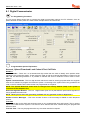
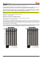
1.3 System Overview
Matrix 832 / 832+ Matrix 424
ZONES
Zones on Main Board
8 fully programmable zones (16
using zone doubling option)
4 fully programmable zones (8 using
zone doubling)
Zone Expander (On Board)
8 fully programmable zones on local
plug In expander (16 using zone
doubling option)
8 fully programmable zones on local
plug In expander (16 using zone
doubling option)
MX-RIX with Zone Analyser
8 fully programmable zones on
remote expander (16 using zone
doubling option)
Not Available
Maximum Zones Capacity
32 zones using zone doubling
option and zone expander
24 zones using doubling option and
zone expander
Zone Configurations
1. Normally closed
2. DEOL – 2 end of line resistors
3. Zone doubling – 1 end of line
resistor
1. Normally closed
2. DEOL – 2 end of line resistors
3. Zone doubling – 1 end of line
resistor
Zone Types
1. Entry / Exit
2. Access
3. Immediate
4. Medical
5. Arm
6. Omitted (Bypassed)
7. Fire
8. PA
9. 24hr
10. Key box
11. Shunt keypad
12. Tamper
13. Key switch Latched
14. Key switch Momentary
15. Unused
1. Entry / Exit
2. Access
3. Immediate
4. Medical
5. Arm
6. Omitted (Bypassed)
7. Fire
8. PA
9. 24hr
10. Key box
11. Shunt keypad
12. Tamper
13. Key switch Latched
14. Key switch Momentary
15. Unused
Zone Attributes
1. Chime
2. Test
3. Mask
4. Double knock
5. Normally Open
6. Normally Closed
1. Chime
2. Test
3. Mask
4. Double knock
5. Normally Open
6. Normally Closed
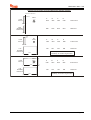
PROGRAMMABLE OUTPUTS
PGM On-Board
Outputs
1. PGM1 – N/O / N/C
2. PGM2 –
(832+) N/O / N/C
(832) Active High / Active Low
3. PGM3 – Active High / Active
Low
4. PGM4 – Active High / Active
Low
1. PGM1 – N/O / N/C
2. PGM2 – Active High / Active Low
3. PGM3 – Active High / Active Low
4. PGM4 – Active High / Active Low
NOTE: Active High switches from 0V to 12V; Active Low switches from 12V to 0V.

Matrix 832 / 832+ / 424
Page 6 RINS428-5
Matrix 832 / 832+ Matrix 424
PGM Options
1. Off
2. PIR remote LED enable (E-)
3. PIR Latch memory (C+)
4. Follow Arm / Disarm
5. Follow zone
6. Follow line fail
7. Follow kiss off
8. Shock / Fire reset
9. Follow strobe
10. Follow Fire Alarm
11. Follow PA
12. Confirmed Alarm
13. Follow Tamper Alarm
14. External Bell
15. GND Fire detector – PGM 4 only
16. Twin Alert – PGM 3 only
17. Follow entry exit
18. Follow Digi Com - Fire Signal
19. Follow Digi Com - PA Signal
20. Follow Digi Com - Intruder Signal
21. Follow Digi Com - Open/Close
22. Follow Digi Com - Spare Signal
23. Follow Digi Com - Medical Signal
24. Follow Digi Com - Conf Signal
25. Follow Digi Com - Omits Signal
26. Follow Hidden Display
27. Follow Mains Fail
28. Follow Battery Low
29. Follow Battery Missing
30. Internal Sounder
PGM Expander MX-ROX
Outputs
1. 8 open collector – Installable
remotely on keypad bus
2. 8 relay expander – installable
remotely on keypad bus
1. 8 open collector – Installable
remotely on keypad bus
2. 8 relay expander – installable
remotely on keypad bus
KEYPADS
Type
1. Two 7 segments LED
2. LCD 32 character
3. ICON
1. Two 7 segments LED
2. LCD 32 character
3. ICON
Dedicated buttons
1. PA
2. Fire
3. Medical
1. PA
2. Fire
3. Medical
Max number
Four of same type (max 6 devices) Four of same type (max 6 devices)
Settings
1. Private - system status indicated
during arming
2. Public - system status indicated
in arm mode
3. Hidden - display suppressed after
20 seconds
1. Private - system status indicated
during arming
2. Public - system status indicated
in arm mode
3. Hidden - display suppressed after
20 seconds
LCD Keypad
Supply Voltage
9-16Vdc 9-16Vdc
Supply Current
80mA – Normal
20mA – Minimum brightness setting
80mA – Normal
20mA – Minimum brightness setting
LED Keypad
Supply Voltage
9-16Vdc 9-16Vdc
Supply Current
60mA Maximum @ 13.8V 60mA Maximum @ 13.8V
ICON Keypad
Supply Voltage
9-16Vdc 9-16Vdc
Supply Current
50mA Maximum @ 13.8V 50mA Maximum @ 13.8V

! Matrix 832 / 832+ / 424
RINS428-5 Page 7
Matrix 832 / 832+ Matrix 424
PROXIMITY READER (Not approved for use in Denmark, Norway, Finland or Sweden)
Type
Inductively coupled key-fob or card Inductively coupled key-fob or card
Max number
Four of same type (max 6 devices) Four of same type (max 6 devices)
Settings
1. Private – system status indicated
during arming
2. Public – system status indicated
in arm mode
1. Private – system status indicated
during arming
2. Public – system status indicated
in arm mode
Supply Voltage
9-16Vdc 9-16Vdc
Supply Current
PARTITIONS
Number of partitions
4 true partitions with common option 4 true partitions with common option
Independent settings
1. Zones
2. Keypads
3. Proximity readers
4. User codes
5. PGMs
6. Timers
7. Reporting account codes
1. Zones
2. Keypads
3. Proximity readers
4. User codes
5. PGMs
6. Timers
7. Reporting account codes
Arm modes
4 arm modes per partition (A, B, C, D) 4 arm modes per partition (A, B, C, D)
Home / Away allocation
Programmable individual arm modes Programmable individual arm modes
Arming options
1. Final door
2. Timed exit
3. Silent arm
4. Forced Arm
1. Final door
2. Timed exit
3. Silent arm
4. Forced Arm
Timers
1. Entry / Exit
2. Bell Delay
3. AC Fault Delay
4. Telephone Line Fault Delay
5. Inactivity Arm Time 10-990min
6. Auto Arm – Time of Day
7. Final Exit Delay
8. Quartz Correction Factor
9. Confirmed Alarm
1. Entry / Exit
2. Bell Delay
3. AC Fault Delay
4. Telephone Line Fault Delay
5. Inactivity Arm Time 10-990min
6. Auto Arm – Time of Day
7. Final Exit Delay
8. Quartz Correction Factor
9. Confirmed Alarm
Real time clock
1. AC frequency Based
2. Quartz Based
1. AC Frequency Based
2. Quartz Based
USER CODES
Number of user codes
32 codes (4 to 6 digits) 32 codes (4 to 6 digits)
User code types
1. Master user per partition
2. Limited user
3. Duress
4. Engineer
5. Arm only - can be used as a
patrol code
6. Disarm only - can be used as a
patrol code
7. Omit (Bypass)
8. Temporary
9. Limited number of uses
1. Master user per partition
2. Limited user
3. Duress
4. Engineer
5. Arm only - can be used as a
patrol code
6. Disarm only - can be used as a
patrol code
7. Omit (Bypass)
8. Temporary
9. Limited number of uses
CENTRAL MONITORING OPTIONS
Telephone Numbers
9 telephone numbers shared with
pager, Pyronix PC format and digital
communication formats
9 telephone numbers shared with
pager, Pyronix PC format and digital
communication formats
Communication Protocols
1. Contact ID
2. Pager Format
3. BSIA Fast Format
4. Pyronix PC Format
5. MX Voice
1. Contact ID
2. Pager Format
3. BSIA Fast Format
4. Pyronix PC Format
5. MX Voice

Matrix 832 / 832+ / 424
Page 8 RINS428-5
CENTRAL MONITORING OPTIONS – Cont.
Group Reporting to CMS
1. Events sent to 1 number only
2. Events sent to 2 numbers
3. Events sent to first number with
backup of second number
1. Events sent to 1 number only
2. Events sent to 2 numbers
3. Events sent to first number with
backup of second number
Programmable Send
Options
1. In disarmed mode
2. In arm modes A, B, C and D
3. Restorals
4. Alarms
5. PAs
6. Fire
7. Maintenance
8. Open / Close
9. Medical
1. In disarmed mode
2. In arm modes A, B, C and D
3. Restorals
4. Alarms
5. PAs
6. Fire
7. Maintenance
8. Open / Close
9. Medical
Test Call
Programmable in days, hours and
minutes
Programmable in days, hours and
minutes
Telephone Line Monitoring
Yes – with status indication Yes – with status indication
Telephone Connection
Allows other telephone on the line Allows other telephone on the line
Digital Communicator
Analogue line Analogue line
Lightning Protection
Heavy duty lightning protection
6.75kV/125Amps
Heavy duty lightning protection
6.75kV/125Amps
OTHER
Software Support
1. UDL programming software
2. Pyronix MX-MON software to be
used with:
a. Modem + Pyronix format
b. RC12/RC112 +
Contact ID/BSIA
1. UDL programming software
2. Pyronix MX-MON software to be
used with:
a. Modem + Pyronix format
b. RC12/RC112 +
Contact ID/BSIA
Memory Event Log
300 events with time and date
Log deletion cannot be allowed either
accidentally or on purpose.
Log reaction time is more than 30
days and the clock will not change
more than + / - 10 mins over 1 year at
20c
300 events with time and date
Log deletion cannot be allowed either
accidentally or on purpose.
Log reaction time is more than 30
days and the clock will not change
more than + / - 10 mins over 1 year at
20c
1.3.1.1 Minimum Installation Requirements
In addition to the main alarm panel (424, 832 or 832+), and any detectors or sensors, at least one keypad is
required. This can be an LCD, LED or ICON keypad. One keypad MUST be set to ID-1. This is the minimum
requirement.
1.3.1.2 Installation Constraints
A maximum of 6 devices can be attached to the Matrix bus (see also Section 4: Cabling Rules for the Matrix
Bus). The following table shows the maximum number of each device type allowable, whilst at the same time
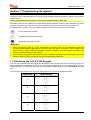
remembering that only 6 devices in total can be on the bus at any one time.
BUS DEVICE MATRIX 832+ /832 MATRIX 424
LCD Keypad 4 4
ICON Keypad 4 4
MX-PROX Proximity Reader 4 4
MX-RIX with Zone Analyser 1 1
On-board Input Expander 1 1
MX-ROX Output Expander 1 1

! Matrix 832 / 832+ / 424
RINS428-5 Page 9
Section 2: Safety & Approvals
SAFETY
1. A technically competent person must carry out the mains installation in accordance with the national and
local electrical installation regulations
2. Protective Earth: This equipment must be earthed/grounded
3. Functional Earth: Must be connected to earth terminal to allow the equipment to operate correctly. Has
no safety implications.
4. Connect the unit to a single pole, unswitched, 3 Amp fused spur, using 0.75mm
2
cable. If the Neutral
cannot be positively identified use a double pole disconnect version.
5. Always remove / isolate the mains supply before carrying out any servicing of the panel.
6. Fuses: For continued protection against the risk of fire, replace only with the same type and rating of
fuse.
7. There are no user serviceable parts inside the equipment.
8. This unit should be mounted so that there will be no outside access to the electrical cable entry point
9. Ventilation: To ensure the correct airflow, always mount the unit vertically with the unit having a clear
space on all sides. It must not be covered by clothes, furnishings, boxes, etc. It must not be mounted
close to, or above, heat radiating sources.
10. On completion of wiring, use tie-wraps to prevent any loose wires causing a safety hazard.
11. The mechanical mounting of the unit must be secure enough to carry the full weight of the unit including
all batteries.
12. Batteries: Ensure that the battery terminal connections will not create an electrical short-circuit on the
case metalwork when the unit is closed. Use insulated battery lead connectors.
13. Dispose of old batteries as required by environmental legislation / recommendations.
14. The battery case must have a flame-retardant rating of UL94-V2/V1/V0 – IEC60950:2000
15. Water: The equipment must be kept free from dampness, water and any other liquids. It is only suitable
for installation indoors.
ICONS
Protective Earth
Must be connected to the electrical installation earth / ground
Protective Bonding
Must be connected to the equipment protective earth terminal
Functional Earth
Must be connected to earth terminal to allow the equipment
to operate correctly. Has no safety implications.
Read
Read equipment instructions
C
O
M
P
L
I
A
N
C
E

Matrix 832 / 832+ / 424
Page 10 RINS428-5

! Matrix 832 / 832+ / 424
RINS428-5 Page 11

Matrix 832 / 832+ / 424
Page 12 RINS428-5
The maximum voltage applied to the equipment must not exceed the safety extra low voltage SELV limits
specified in IEC60950 / EN60950 / UL60950 30VDC / 30VAC / 42.4Vpeak
If you need to switch greater voltage, current or power you will require the use of a separate external
switching relay

! Matrix 832 / 832+ / 424
RINS428-5 Page 13
PYRONIX Ltd
Pyronix House
Braithwell Way
Hellaby,
Rotherham
South Yorkshire
S66 8QY
HTTP://www.pyronix.com ENGLAND, UK
______________________________________________________________
EU Declaration of Conformity
EN45014
Manufacturer: As above
Details of electrical equipment
Model name(s) Matrix 832+ (Plastic & Metal Housing)
MX-ROX8T, MX-ROX8R, MX-RIX with Zone Analyser
LCD, LED, Icon keypads, MX-PROX
Description: Control & Indicating Equipment
Remote expanders, keypads
Directives that this equipment RTTE 99/05/EC
complies with:
Harmonised Standards applied EN50081-1: 1992 Class B
in order to verify compliance EN50130-4: 1995 + A1: 1998
with the Directives: EN301489-1: V1.4.1
EN301489-3: V1.3.1
EN300330-2: V1.1.1
Testing Agency Status ISO/IEC17025 Certificate No Cert.
Date
Category
York EMC Services
Three Lanes End Centre
Methley
Castleford
West Yorkshire
WF10 1PN
KTL, Saxon Way
Priory Park West
Hull, Humberside
HU13 PB9
Testhouse
Testhouse
UKAS 1574
UKAS 0971
5212TC
5503/TR/1
5494/TR/1
5430/TR/1
1C5217CEU1
1C521CCB1
2H5972GEU1
02/01/02
01/04/03
20/03/03
02/01/03
01/10/02
11/10/02
21/11/02
EMC
EMC
EMC
EMC
Safety
Safety
Radio
Year in which CE mark was affixed: 2002
Authorized signatory:
Manufacturer Authorized Representative Date of issue
01 June 03
.................................. .............................................. Place of issue
Name: Craig Leivers Not applicable Pyronix Ltd
Position: R & D Director

Matrix 832 / 832+ / 424
Page 14 RINS428-5
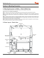
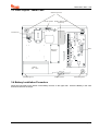
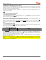
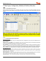
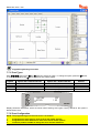
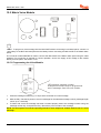
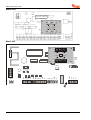
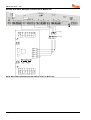
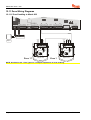
Section 3: Mounting Procedure
3.1 Mounting Procedure for Matrix – Plastic & Metal Case
The following steps illustrate basic mounting procedure for matrix plastic & metal case.
(See section 12 for complete wiring diagrams)
Step 1 - Remove the case lid from the matrix panel and check all parts and components are in place.
Step 2 - Decide where the matrix panel will be situated. The matrix panel may be housed in the loft or
different rooms in the premises. A discrete and concealed place is advisable, as only the Matrix keypads need
to be seen.
Step 3 - Secure the matrix panel to a sturdy and stable surface, using the mounting screws provided. First
mark the wall where the panel is to be situated (using the mounting holes), drill holes in the wall, and fasten
the panel base to the wall using the screws supplied.
Step 4 - Before the panel base is completely secured to the wall feed cables for keypads / AC power supply /
and accessories through the cable entry holes as illustrated.
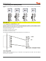
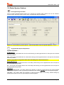
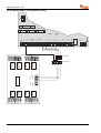
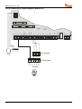
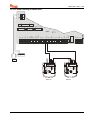
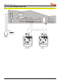
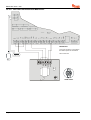
3.2 Panel Layout – Plastic Case
Battery
Support
Battery
Wall Fixing
Hole
Wall Fixing
Hole
Tamper
Switch
Wall Fixing
Holes
Transformer
Mains Cable
Entry Hole
Cable Entry
Hole
Wall Fixing
Hole
La pagina si sta caricando...
La pagina si sta caricando...
La pagina si sta caricando...
La pagina si sta caricando...
La pagina si sta caricando...
La pagina si sta caricando...
La pagina si sta caricando...
La pagina si sta caricando...
La pagina si sta caricando...
La pagina si sta caricando...
La pagina si sta caricando...
La pagina si sta caricando...
La pagina si sta caricando...
La pagina si sta caricando...
La pagina si sta caricando...
La pagina si sta caricando...
La pagina si sta caricando...
La pagina si sta caricando...
La pagina si sta caricando...
La pagina si sta caricando...
La pagina si sta caricando...
La pagina si sta caricando...
La pagina si sta caricando...
La pagina si sta caricando...
La pagina si sta caricando...
La pagina si sta caricando...
La pagina si sta caricando...
La pagina si sta caricando...
La pagina si sta caricando...
La pagina si sta caricando...
La pagina si sta caricando...
La pagina si sta caricando...
La pagina si sta caricando...
La pagina si sta caricando...
La pagina si sta caricando...
La pagina si sta caricando...
La pagina si sta caricando...
La pagina si sta caricando...
La pagina si sta caricando...
La pagina si sta caricando...
La pagina si sta caricando...
La pagina si sta caricando...
La pagina si sta caricando...
La pagina si sta caricando...
La pagina si sta caricando...
La pagina si sta caricando...
La pagina si sta caricando...
La pagina si sta caricando...
La pagina si sta caricando...
La pagina si sta caricando...
La pagina si sta caricando...
La pagina si sta caricando...
La pagina si sta caricando...
La pagina si sta caricando...
La pagina si sta caricando...
La pagina si sta caricando...
La pagina si sta caricando...
La pagina si sta caricando...
La pagina si sta caricando...
La pagina si sta caricando...
La pagina si sta caricando...
La pagina si sta caricando...
La pagina si sta caricando...
La pagina si sta caricando...
La pagina si sta caricando...
La pagina si sta caricando...
La pagina si sta caricando...
La pagina si sta caricando...
La pagina si sta caricando...
La pagina si sta caricando...
La pagina si sta caricando...
La pagina si sta caricando...
La pagina si sta caricando...
La pagina si sta caricando...
La pagina si sta caricando...
La pagina si sta caricando...
La pagina si sta caricando...
La pagina si sta caricando...
La pagina si sta caricando...
La pagina si sta caricando...
La pagina si sta caricando...
La pagina si sta caricando...
La pagina si sta caricando...
La pagina si sta caricando...
La pagina si sta caricando...
La pagina si sta caricando...
La pagina si sta caricando...
La pagina si sta caricando...
La pagina si sta caricando...
La pagina si sta caricando...
La pagina si sta caricando...
La pagina si sta caricando...
La pagina si sta caricando...
La pagina si sta caricando...
La pagina si sta caricando...
La pagina si sta caricando...
La pagina si sta caricando...
La pagina si sta caricando...
La pagina si sta caricando...
La pagina si sta caricando...
La pagina si sta caricando...
La pagina si sta caricando...
La pagina si sta caricando...
La pagina si sta caricando...
La pagina si sta caricando...
La pagina si sta caricando...
La pagina si sta caricando...
La pagina si sta caricando...
La pagina si sta caricando...
La pagina si sta caricando...
La pagina si sta caricando...
La pagina si sta caricando...
La pagina si sta caricando...
La pagina si sta caricando...
La pagina si sta caricando...
La pagina si sta caricando...
La pagina si sta caricando...
La pagina si sta caricando...
La pagina si sta caricando...
La pagina si sta caricando...
La pagina si sta caricando...
La pagina si sta caricando...
La pagina si sta caricando...
La pagina si sta caricando...
La pagina si sta caricando...
La pagina si sta caricando...
La pagina si sta caricando...
La pagina si sta caricando...
La pagina si sta caricando...
La pagina si sta caricando...
La pagina si sta caricando...
La pagina si sta caricando...
La pagina si sta caricando...
La pagina si sta caricando...
La pagina si sta caricando...
La pagina si sta caricando...
La pagina si sta caricando...
La pagina si sta caricando...
La pagina si sta caricando...
La pagina si sta caricando...
La pagina si sta caricando...
La pagina si sta caricando...
La pagina si sta caricando...
La pagina si sta caricando...
La pagina si sta caricando...
La pagina si sta caricando...
La pagina si sta caricando...
La pagina si sta caricando...
La pagina si sta caricando...
La pagina si sta caricando...
-
 1
1
-
 2
2
-
 3
3
-
 4
4
-
 5
5
-
 6
6
-
 7
7
-
 8
8
-
 9
9
-
 10
10
-
 11
11
-
 12
12
-
 13
13
-
 14
14
-
 15
15
-
 16
16
-
 17
17
-
 18
18
-
 19
19
-
 20
20
-
 21
21
-
 22
22
-
 23
23
-
 24
24
-
 25
25
-
 26
26
-
 27
27
-
 28
28
-
 29
29
-
 30
30
-
 31
31
-
 32
32
-
 33
33
-
 34
34
-
 35
35
-
 36
36
-
 37
37
-
 38
38
-
 39
39
-
 40
40
-
 41
41
-
 42
42
-
 43
43
-
 44
44
-
 45
45
-
 46
46
-
 47
47
-
 48
48
-
 49
49
-
 50
50
-
 51
51
-
 52
52
-
 53
53
-
 54
54
-
 55
55
-
 56
56
-
 57
57
-
 58
58
-
 59
59
-
 60
60
-
 61
61
-
 62
62
-
 63
63
-
 64
64
-
 65
65
-
 66
66
-
 67
67
-
 68
68
-
 69
69
-
 70
70
-
 71
71
-
 72
72
-
 73
73
-
 74
74
-
 75
75
-
 76
76
-
 77
77
-
 78
78
-
 79
79
-
 80
80
-
 81
81
-
 82
82
-
 83
83
-
 84
84
-
 85
85
-
 86
86
-
 87
87
-
 88
88
-
 89
89
-
 90
90
-
 91
91
-
 92
92
-
 93
93
-
 94
94
-
 95
95
-
 96
96
-
 97
97
-
 98
98
-
 99
99
-
 100
100
-
 101
101
-
 102
102
-
 103
103
-
 104
104
-
 105
105
-
 106
106
-
 107
107
-
 108
108
-
 109
109
-
 110
110
-
 111
111
-
 112
112
-
 113
113
-
 114
114
-
 115
115
-
 116
116
-
 117
117
-
 118
118
-
 119
119
-
 120
120
-
 121
121
-
 122
122
-
 123
123
-
 124
124
-
 125
125
-
 126
126
-
 127
127
-
 128
128
-
 129
129
-
 130
130
-
 131
131
-
 132
132
-
 133
133
-
 134
134
-
 135
135
-
 136
136
-
 137
137
-
 138
138
-
 139
139
-
 140
140
-
 141
141
-
 142
142
-
 143
143
-
 144
144
-
 145
145
-
 146
146
-
 147
147
-
 148
148
-
 149
149
-
 150
150
-
 151
151
-
 152
152
-
 153
153
-
 154
154
-
 155
155
-
 156
156
-
 157
157
-
 158
158
-
 159
159
-
 160
160
-
 161
161
-
 162
162
-
 163
163
-
 164
164
-
 165
165
-
 166
166
-
 167
167
-
 168
168
-
 169
169
-
 170
170


Pyronix Matrix 832 Guida d'installazione
- Categoria
- Antincendio
- Tipo
- Guida d'installazione
- Questo manuale è adatto anche per
in altre lingue
Documenti correlati
-
Pyronix Matrix 832 Programming Manual
-
Pyronix Matrix 832 Manuale utente
-
-
-
-
-
-
-
-
Altri documenti
-
Honeywell EKZ008200B Manuale utente
-
Aritech CS350 Installation Instructions Manual
-
PARADOX Esprit+ 642 Installer's Manual
-
ADEMCO Vista-20PCN Manuale utente
-
Risco Agility Manuale utente
-
Aritech CS-175-275-575 Series Manuale utente
-
DSC PK5500 Guida d'installazione
-
Motorola SDC1000 Istruzioni per l'uso
-
Nice Automation MORX Manuale del proprietario
-