ProLights RAZOR440 Manuale utente
- Categoria
- Proiettori
- Tipo
- Manuale utente

USER MANUAL
MANUALE UTENTE
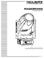
RAZOR440
HYBRID BEAM
EN - IT

All rights reserved by Music & Lights S.r.l. No part of this instruction manual may be
reproduced in any form or by any means for any commercial use.
In order to improve the quality of products, Music&Lights S.r.l. reserves the right to modify the
characteristics stated in this instruction manual at any time and without prior notice.
All revisions and updates are available in the ‘manuals’ section on site www.musiclights.it
REV. 03-08/19

1
RAZOR440
Packing content
• RAZOR440
• Mount bracket
• Power supply cable and signal cable
• Safety rope
• User manual
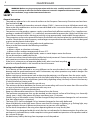
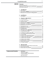
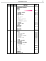
TABLE OF CONTENTS
Safety
General instructions
Warnings and installation precautions
General information
1 Introduction
1. 1 Description
1. 2 Technical specications
1. 3 Operating elements and connections
2 Installation
2. 1 Mounting
3 Functions and settings
3. 1 Operation
3. 2 Basic
3. 3 Menu structure
3. 4 Slave Receive mode
3. 5 Operation in automatic mode
3. 6 Scenes Record mode
3. 7 Music mode
3. 8 Sensitivity microphone
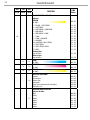
3. 9 Linking
3. 10 DMX mode
3. 11 DMX conguration
3. 12 DMX addressing
3. 13 Connection of the DMX line
3. 14 Construction of the DMX termination
3. 15 DMX control
3. 16 Wireless control settings
3. 17 Fixture settings
3. 18 Lamp settings
3. 19 Display settings
3. 20 Fixture information
3. 21 Reset functions
3. 22 Special functions
4 Maintenance
4. 1 Maintenance and cleaning the unit
4. 2 Fuse replacement
4. 3 Trouble shooting
2
2
3
4
4
7
8
9
9
10
13
13
14
15
15
15
15
16
16
17
17
18
27
27
27
28
28
29
29
32
32
33

RAZOR440
2
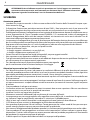
WARNING! Before carrying out any operations with the unit, carefully read this instruction
manual and keep it with cure for future reference. It contains important information about
the installation, usage and maintenance of the unit.
SAFETY
General instruction
• The products referred to in this manual conform to the European Community Directives and are there-
fore marked with
.
• The unit is supplied with hazardous network voltage (230V~). Leave servicing to skilled personnel only.
Never make any modications on the unit not described in this instruction manual, otherwise you will
risk an electric shock.
• Connection must be made to a power supply system tted with ecient earthing (Class I appliance ac-
cording to standard EN 60598-1). It is, moreover, recommended to protect the supply lines of the units
from indirect contact and/or shorting to earth by using appropriately sized residual current devices.
• The connection to the main network of electric distribution must be carried out by a qualied electrical
installer. Check that the main frequency and voltage correspond to those for which the unit is designed
as given on the electrical data label.
• This unit is not for home use, only professional applications.
• Never use the xture under the following conditions:
- in places wet;
- in places subject to vibrations or bumps;
- in places with an ambient temperature of over 45°C.
• Make certain that no inammable liquids, water or metal objects enter the xture.
• Do not dismantle or modify the xture.
• All work must always be carried out by qualied technical personnel. Contact the nearest sales point for
an inspection or contact the manufacturer directly.
• If the unit is to be put out of operation denitively, take it to a local recycling
plant for a disposal which is not harmful to the environment.
Warnings and installation precautions
• If this device will be operated in any way dierent to the one described in this manual, it may suer
damage and the guarantee becomes void. Furthermore, any other operation may lead to dangers like
short circuit, burns, electric shock, etc.
• Before starting any maintenance work or cleaning the projector, cut o power from the main supply.
• Always additionally secure the projector with the safety rope. When carrying out any work, always com-
ply scrupulously with all the regulations (particularly regarding safety) currently in force in the country
in which the xture’s being used.
• For inside use only. Not designed for outside use.
• The minimum distance between the xture and surrounding walls must be more than 50 cm and the
air vents at the housing must not be covered in any case.
• Install the xture in a well ventilated place.
• Keep any inammable material at a safe distance from the xture.
• The maximum temperature that can be reached on the external surface of the tting, in a thermally
steady state, is high. After power o, please cool down over 15 minutes.
• Shields, lenses or ultraviolet screens shall be changed if they have become damaged to such an extent
that their eectiveness is impaired.
• The lamp (LED) shall be changed if it has become damaged or thermally deformed.
• Never look directly at the light beam. Please note that fast changes in lighting, e. g. ashing light, may
trigger epileptic seizures in photosensitive persons or persons with epilepsy.
• Do not touch the product’s housing when operating because it may be very hot.
• This product was designed and built strictly for the use indicated in this documentation. Any other use,
not expressly indicated here, could compromise the good condition/operation of the product and/or
be a source of danger.
• We decline any liability deriving from improper use of the product.

3
RAZOR440
- 1 - INTRODUCTION
1.1 DESCRIPTION
RAZOR440 is a hybrid moving light delivering a full toolkit for designers in a single xture. Harnessing the
power of the 440 W discharge source with a custom optical system, it provides a punchy beam, even wash
and crisp spot - all from a single unit.
1.2 TECHNICAL SPECIFICATIONS
LIGHT SOURCE
• Source: 440W S Osram Sirius HRI
• CT: 7.000K
• Luminous ux: 15’700lm
• Lux: (2°) 140’000lx @15 m
• Lux: (50°) 3’000lx @10 m
• Source life expectancy: 1.500 h
OPTICS
• Zoom: 2° ~ 50° motorised linear zoom
• Lens diameter: 153mm
• Lens type: high-quality glass lens optics
• Focus: motorised with auto-focus
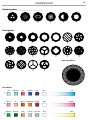
COLOUR SYSTEM
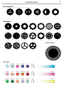
• Colour mixing: CMY colour system on 3 gradually fading colour wheels
• CTC: on wheel 2500 K and 3200 K + CTB
• Colour wheel: 13 dichroic lters + open on 3 independent colour wheels
DYNAMIC EFFECTS
• Animation wheel: animation wheel with CW and CCW rotation
• Rotating gobos: 6 rotating gobos + open, interchangeable, indexing
• Gobo size: outer: 25,7 mm - image: 13 mm - thickness: 1,1 mm
• Fixed gobos: 18 xed gobos + open
• Circular prism: 3f with bi-directional rotation, indexing
• Linear prism: 6f with bi-directional rotation, indexing
• Frost: linear 0 - 100% frost lter
BODY
• Pan angle: 630° - 540°
• Tilt angle: 267°
• Pan/Tilt resolution: 8 / 16 bit
• Feedback: automatic repositioning after accidental movement
• Body: aluminium structure with hi-resistance polycarbonate cover
• Body colour: black
CONTROL
• Protocols: DMX512, RDM, Art-Net, W-DMX
• DMX channels: 21 / 24 / 26channel
• W-DMX: included, wireless solution receiver
• RDM: RDM ready for xture remote monitor and settings

RAZOR440
4
• Display: LCD high resolution colour display with autoip
• Firmware upgrade: via menu with internal memory or via USB - DMX interface (UPBOX2) not included
• Hibernation: power safe mode when lost DMX
ELECTRONICS
• Dimmer: linear 0 ~ 100% mechanical dimmer
• Strobe / shutter: 1 - 28 ash(s), mechanical
• Battery backup: battery backup for user operation without connecting to the main power
• Operating temperature: -10° ~ +45°
ELECTRICAL
• Power supply: 100-240 V – 50/60 Hz
• Power consumption (at 230V): 585W
• Power consumption (at 120V): 585W
PHYSICAL
• Cooling: combination of heat pipe cooling system and low noise fan
• Sospension and xing: any position with quick-lock omega brackets
• Pan / tilt lock: pan / tilt locking for transportation and maintenance
• Signal connection: Amphenol XLR 5p IN/OUT connectors
• Data connection: Art-Net RJ45 IN/OUT
• Power connection: Neutrik powerCON TRUE1 IN connector
• IP rating: 20
• Dimensions (WxHxD): 411x714x258mm
• Weight: 27kg

5
RAZOR440
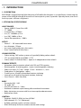
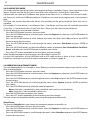
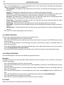
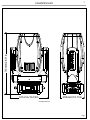
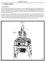
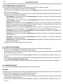
Fig.1
Technical drawing
714mm/28.11in
411mm/16.18in 258mm/10.15in

RAZOR440
6
1
2
3
5
4
6
8
7
9
12
10
13
11
A
B
14
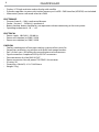
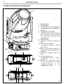
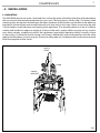
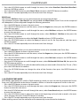
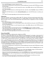
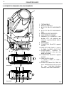
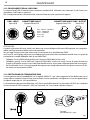
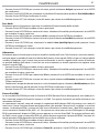
1.3 OPERATING ELEMENTS AND CONNECTIONS
1. MOVING HEAD
2. ROTARY ARM
3. TILT Mechanism Lock and Release
4. PAN Mechanism Lock and Release
5. HANDLE
6. LED INDICATOR "W-DMX"
7. CONTROL PANEL with LCD display
and 5 button used to access
the control panel functions and
manage them.
8. MICROPHONE
9. EtherCON connector Signal IN/
OUT
10. DMX OUT (5-pole XLR):
1 = ground, 2 = DMX-, 3 = DMX+,
4 N/C, 5 N/C
11. MAIN FUSE HOLDER: replace a
burnt-out fuse by one of the same
type only.
12. EtherCON connector Signal IN/
OUT
13. DMX IN (5-pole XLR):
1 = ground, 2 = DMX-, 3 = DMX+,
4 N/C, 5 N/C
14. POWER IN (PowerCON TRUE
IN): for connection to a socket
(100-240V~/50-60Hz) via the
supplied mains cable.
Fig.2
View A
View B

7
RAZOR440
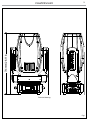
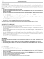
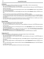
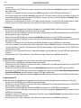
Fig.3
CLAMP
SAFETY
CABLE
OMEGA
BRACKETS
- 2 - INSTALLATION
2.1 MOUNTING
The RAZOR440 may be set up on a solid and even surface. By means of the xing facilities of the baseplate,
the unit can also be mounted upside down to a cross arm. The base plate is shown in g.3. For xing, stable
mounting clips are required. According to the gure, the bolts of the brackets are placed into the openings
provided in the base plate and turned clockwise until they lock (to the stop). Always ensure that the unit
is rmly xed to avoid vibration and slipping while operating. The mounting place must be of sucient
stability and be able to support a weight of 10 times of the unit’s weight. When carrying out any installa-
tion, always comply scrupulously with all the regulations (particularly regarding safety) currently in force
in the country in which the xture’s being used. Always additionally secure the projector with the safety
rope from falling down. For this purpose, fasten the safety rope at a suitable position so that the maximum
fall of the projector will be 20 cm.

RAZOR440
8
- 3 - FUNCTIONS AND SETTINGS
3.1 OPERATION
Connect the supplied main cable to a socket (100-240V~/50-60Hz). The unit will run built-in program to
reset all motors to their home position. Shortly after that the RAZOR440 is ready for operation. To switch
o, disconnect the mains plug from the socket. For a more convenient operation it is recommended to
connect the unit to a socket which can be switched on and o via light switch.
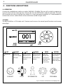
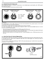
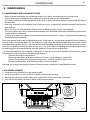
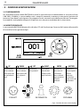
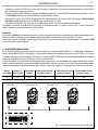
3.2 BASIC
The RAZOR440 has a LCD display and 5 button used to access the control panel functions and manage
them (g.4).
Fig.4 - Functions of the buttons and display icons
CONNECT
LIGHT
INFORMATION
SET
PROGRAM
LEFT RIGHT UP DOWN ENTER BATTERY
Return to the top
level
Commute from
units, tens, hundred
in the menu
Increases the value
displayed or passes
to the previous item
in a menu
Decreases the value
displayed or passes
to the next item in
the menu
Conrms the
displayed value,
or activates the
displayed function,
or enters the
successive menu
Used to activate the
backup battery. It
allows to switching
display interface
without main power

9
RAZOR440
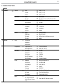
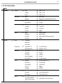
3.3 MENU STRUCTURE
MENU
1 CONNECT
ð
Address
ð
DMX
ð
Value (1-512)
W-DMX
ð
Value (1-512)
Artnet
ð
Value (1-512)
DMX Mode
ð
Mode
ð
Bas/Std/Ext
Edit User
ð
Max Channel/Control/Pan/Pan Fine/Tilt/...
Wireless
ð
DMX Out
ð
ON/OFF
Reset Connect
ð
YES/NO
Ethernet
ð
DMX Out
ð
ON/OFF
IP Address
ð
2.XX.XX.01
IP Mask
ð
255.0.0.0
Universe
ð
00000
RDM ID
ð
Name
ð
Fixture ID Name
RDM Mode
ð
Mode1/Mode2
Password
ð
050 (unlocks the following settings)
PID Code
ð
00001
2 SET UP
ð
Lamp
ð
Turn On/O
Automatic
Dmx control
Temperature
ð
Temperature C/F
ð
Celsius/Fahrenheit
Max Temperature
ð
Value (60°-139° C)
Movement
ð
Pan Reverse
ð
YES/NO
Tilt Reverse
ð
YES/NO
Pan Degree
ð
540/630
Pan/Tilt Feedbacks
ð
YES/NO
Pan/Tilt Mode
ð
Standard/Smooth
Screen
ð
Backlight
ð
Always On/Min (01-99)
Flip Display
ð
YES/NO/AUTO
Display Bright
ð
Value (00-31)
Key Lock
ð
ON/OFF
Language
ð
EN/FR/SP...
Fixture
ð
Fans Mode
ð
Auto Speed/High Speed
No Signal
ð
Close/Hold/Auto/Music
Hibernation
ð
Disable/Min (01-99)
Adjust
ð
Control, Pan, Pan Fine,
Tilt, Tilt Fine, Pan&Tilt
Speed, Shutter, Dimmer,
[...]
ð
Value (000-255) for each function

RAZOR440
10
3 ADVANCED
ð
Reset
ð
All
Pan & Tilt
Others
Calibration
ð
Password
ð
050 (unlocks the following settings)
Pan
ð
Value (-128-127)
Tilt
ð
Value (-128-127)
Dimmer
ð
Value (-128-127)
Cyan
ð
Value (-128-127)
Magenta
ð
Value (-128-127)
Yellow
ð
Value (-128-127)
Gobo1
Gobo2
Prism 1
Prism 2
Frost
Focus
Zoom
Animation
Reload Default
ð
Basic Reload
ð
ON/OFF
Program Reload
ð
ON/OFF
Password
ð
050 (unlocks the following settings)
Private Reload
ð
ON/OFF
All Reload
ð
ON/OFF
4 INFORMATION
ð
Time I nfo.
Lamo Info.
Temperature
Fans Speed
Channel Value
Error Message
Fixture Model
Software Ver.
5 STAND ALONE
ð
Play
ð
DMX Receive
Slave Receive
ð
Part 1-2-3 Receive
Static
ð
1-250 Scene
Sequence
ð
Alone/Master
Music
ð
Alone/Master
Mic Sens.
ð
Value (00-99%)

11
RAZOR440
Select Chase
ð
Chase Part 1
ð
Chase 1 - Chase 8
Chase Part 2 Chase 1 - Chase 8
Chase Part 3
ð
Chase 1 - Chase 8
Edit Chase
ð
Chase 1
ð
Step 1 - 64
Chase 2 Step 1 - 64
....
Chase 8
ð
Step 1 - 64
Edit Scenes
ð
Edit Scenes 001
ð
Pan/Pan Fine/Tilt/Tilt Fine/...
Edit Scenes ...
ð
Pan/Tilt/CMY, Gobo1...
Edit Scenes 250
ð
Pan/Tilt/CMY, Gobo1...
Scenes Record
ð
Sc XX - Sc XX

RAZOR440
12
3.4 SLAVE RECEIVE MODE
This mode will allow you to link up the units together without a controller. Choose a unit to function as the
Master. The unit must be the rst unit in line; other units will work as slave with the same eect.
A Master unit can send up to 3 dierent data groups to the Slave units, i.e. a Master unit can start 3 dier-
ent Slave units, which run 3 dierent programs. The Master unit sends the 3 program parts in a continuous
loop.
The Slave unit receives data from the Master unit according to the group which the Slave unit was as-
signed to.
For example, if a slave device is set to Receive Part 1, the Master unit Slave unit will send the automated
Chase Part 1; if set to Receive Part 2, the Chase Part 2 Slave units will receive from the Master.
To set the drive as a slave, proceed as follows:
• Press the ENTER button to access the main menu.
• Press the UP/DOWN button to scroll the menu, select the Program icon, then press the ENTER button to
enter the next menu.
• Press the UP/DOWN button to scroll through the menu, and then select Play and press the ENTER
button to enter the next menu.
• Press the UP/DOWN button to scroll through the menu, and select Slave Receive and press ENTER to
conrm.
• Press the UP/DOWN button to select the dierent modes of operation Part 1 Receive/Receive Part 2/Part 3
Receive, and then press the ENTER button to conrm your choice.
• Press the LEFT button repeatedly to exit the menu and save changes.
Select the desired program on the master unit (described in section 3.5).
Use the DMX connectors of the RAZOR440 and an XLR cable to form a chain of units. Under certain
conditions and lengths you want to make a termination as shown on page 16.
3.5 OPERATIONS IN AUTOMATIC MODE
The unit independently runs through its show. Before you send an automatic program you need to set the
drive as Master/Alone:
• Press the ENTER button to access the main menu.
• Press the UP/DOWN button to scroll the menu, select the Program icon, then press the ENTER button to
enter the next menu.
• Press the UP/DOWN button to scroll through the menu, select Play and press the ENTER button to enter
the next menu.
• Press the UP/DOWN button to scroll through the menu, select Sequence and press ENTER to conrm
your choice.
• Press the UP/DOWN button to select the mode of operation:
- Master, if the unit is connected in series with other units and it acts as the Master;
- Alone, if the unit is not connected to other units.
• Press the ENTER button to conrm your choice.
• Press the LEFT button repeatedly to exit the menu and save changes.
The unit will go into automatic mode by executing the program automatically.
Select Chase
The function Select Chase lets you choose the automatic program to actually run.
• Press the ENTER button to access the main menu.
• Press the UP/DOWN button to scroll the menu, select the Program icon, then press the ENTER button to
enter the next menu.
• Press the UP/DOWN button to scroll through the menu, select Select Chase and press the ENTER button
to enter the next menu.

13
RAZOR440
• Press the UP/DOWN button to scroll through the menu, then select Chase Part 1/Chase Part 2/Chase Part 3
and press ENTER to conrm.
• Press the UP/DOWN button to select Chase1-Chase8, and press the ENTER button to conrm.
• Press the LEFT button repeatedly to exit the menu and save changes.
Edit Chases
The function Edit Chases allows you to create automatic pre-programmed show.
The automatic programs Chase Part1/2/3 are each divided into Chase1-Chase8. Each Chase can be composed
of 1-64 step that can be congured through the following procedure:
• Press the ENTER button to access the main menu.
• Press the UP/DOWN button to scroll the menu, select the Program icon, then press the ENTER button to
enter the next menu.
• Press the UP/DOWN button to scroll through the menu, select Edit Chases and press the ENTER button
to enter the next menu.
• Press the UP/DOWN button to scroll through the menu, select Edit Chase 1 - Edit Chase 8, then press the
ENTER button to conrm.
• Press the UP/DOWN button to select the Step 01 - Step 64, and press ENTER to conrm.
• Press the UP/DOWN button to select the Scene you want to set for the Step chosen, and then press
ENTER to conrm.
• Press the LEFT button repeatedly to exit the menu and save changes.
Edit Scenes
The function Edit Scenes allows you to create individual scenes to be included in the Chase Step.
• Press the ENTER button to access the main menu.
• Press the UP/DOWN button to scroll the menu, select the Program icon, then press the ENTER button to
enter the next menu.
• Press the UP/DOWN button to scroll through the menu, select Edit Scenes and press the ENTER button
to enter the next menu.
• Press the UP/DOWN button to scroll through the menu, select Edit Scene 001 - Edit Scene 250, then press the
ENTER button to conrm.
• Press the UP/DOWN button to select the desired function you want to edit (Control, Pan, Tilt, etc..), Then
press the ENTER button to conrm.
• Press the UP/DOWN button to change the value of the function, then press the ENTER button to
conrm.
• Press the LEFT button repeatedly to exit the menu and save changes.
3.6 SCENES RECORD MODE
RAZOR440 is equipped with a built-in DMX recorder by which you can transmit the programmed scenes
from your DMX-controller to the device. Proceed as follows to store the sequence of scenes in the unit.
• Press the ENTER button to access the main menu.
• Press the UP/DOWN button to scroll through the menu, select the Program icon, then press the ENTER
button to enter the next menu.
• Press the UP/DOWN button to scroll through the menu, select Scenes Record and press the ENTER button
to enter the next menu.
• Press the UP/DOWN button to adjust the scene at the beginning and end to be inserted in the auto-
matic program, then press the ENTER button to conrm.
• Press the LEFT button repeatedly to exit the menu and save changes.
When recalling scenes from the controller will automatically be transmitted to the device.

RAZOR440
14
3.7 MUSIC MODE
In music mode, via its integrated microphone, the unit can be controlled by music with a clear rhythm in
the bass range. If the music control should not work optimally, increase the volume or reduce the distance
between the sound source and the light eect unit or alternatively increase the sensitivity of the micro-
phone.
• Press the ENTER button to access the main menu.
• Press the UP/DOWN button to scroll the menu, select the Program icon, then press the ENTER button to
enter the next menu.
• Press the UP/DOWN button to scroll through the menu, select Play and press the ENTER button to enter
the next menu.
• Press the UP/DOWN button to scroll through the menu, select Music and press ENTER to conrm.
• Press the UP/DOWN button to select the mode of operation:
- Master, if the mobile head is connected in series to other units, and it performs the Master function;
- Alone, if the xture is not connected to other units.
• Press the ENTER button to conrm your choice.
• Press the LEFT button repeatedly to exit the menu and save changes.
The unit will go into music mode by executing an automatic program to the rhythm of music.
3.8 SENSITIVITY MICROPHONE
Select this function to set the value of the sensitivity of the microphone for use with a music control:
• Press the ENTER button to access the main menu.
• Press the UP/DOWN button to scroll the menu, select the Set icon, then press the ENTER button to enter
the next menu.
• Press the UP/DOWN button to scroll through the menu, select UI Set, and press the ENTER button to
enter the next menu.
• Press the UP/DOWN button to scroll through the menu, then select Mic Sens. and press ENTER to conrm.
• Press the UP/DOWN button to adjust the level of sensitivity of the microphone, and then press the
ENTER button to conrm your choice.
• Press the LEFT button repeatedly to exit the menu and save changes.
3.9 LINKING
Several units may be interconnected in order to control all further slave units to the same eect of the
master unit.
1. Connect the DMX OUT of the master unit via 5-pole XLR cable to the DMX IN of the rst slave unit.
2. Connect the DMX OUT of the rst slave unit to the DMX IN of the second slave unit, etc. until all units
are connected in a chain.
3.10 DMX MODE
To enter the DMX mode, follow these steps:
• Press the ENTER button to access the main menu.
• Press the UP/DOWN button to scroll the menu, select the Connect icon, then press the ENTER button to
enter the next menu.
• Press the UP/DOWN button to scroll through the menu, select the DMX Address and press the ENTER key.
• Press the arrow keys to select the desired value (001-512).
• Press the ENTER key to conrm the setting.
• Press the LEFT button repeatedly to exit the menu and save changes.

15
RAZOR440
3.11 DMX CONFIGURATION
The RAZOR440 has 3 DMX channel congurations which can be accessed from the control panel.
• Press the ENTER button to access the main menu.
• Press the UP/DOWN button to scroll the menu, select the Set icon, then press the ENTER button to enter
the next menu.
• Press the UP/DOWN button to scroll through the menu, select Users and press the ENTER button to
enter the next menu.
• Press the UP/DOWN button to scroll through the menu, select User Mode and press ENTER to conrm
your choice.
• Use the UP/DOWN button to select the desired DMX channel conguration (Standard, Extended, Basic),
then press the ENTER button to conrm your choice.
• Press the LEFT button repeatedly to exit the menu and save changes.
The tables on page 18 show the mode of operation and their values DMX.
The unit is equipped with 5-pole XLR connections.
Edit User
The Edit User, in the same menu, allows you to create a prole of personalized functions. You can change
the parameters of the various functions (Control, Pan, Tilt, etc.). Once you’ve created your custom prole,
you can use it by selecting the USER mode as described above.
3.12 DMX ADDRESSING
For operation via light control unit with DMX512 protocol, is sucient connect the controller to RAZOR440.
To able to operate the RAZOR440 with a light controller, adjust the DMX start address for the rst a DMX
channel. If e. g. address 33 on the controller is provided for controlling the function of the rst DMX chan-
nel, adjust the start address 33 on the RAZOR440. The other functions of the light eect panel are then
automatically assigned to the following addresses. An example with the start address 33 is shown below:
Number of
DMX channels
Start address
(example)
DMX Address
occupied
Next possible start
address for unit No. 1
Next possible start
address for unit No. 2
Next possible start
address for unit No. 3
23 33 33-55 56 79 102
DMX Address: 102DMX Address: 56DMX Address: 33 DMX Address: 79
Fig.5 - Example 23 DMX channels conguration
. . . . . . . . . . . .
DMX512 Controller

RAZOR440
16
Fig.6
Fig.7
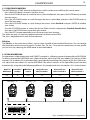
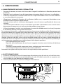
3.13 CONNECTION OF THE DMX LINE
DMX connection employs standard XLR connectors. Use shielded pair-twisted cables with 120Ω imped-
ance and low capacity.
The following diagram shows the connection mode:
ATTENTION
The screened parts of the cable (sleeve) must never be connected to the system’s earth, as this would
cause faulty xture and controller operation.
Over long runs can be necessary to insert a DMX level matching amplier.
For those connections the use of balanced microphone cable is not recommended because it cannot
transmit control DMX data reliably.
• Connect the controller DMX input to the DMX output of the rst unit.
• Connect the DMX output to the DMX input of the following unit. Connect again the output to the input
of the following unit until all the units are connected in chain.
• When the signal cable has to run longer distance is recommended to insert a DMX termination on the
last unit.
3.14 CONSTRUCTION OF THE DMX TERMINATION
The termination avoids the risk of DMX 512 signals being reected back along the cable when they reach-
es the end of the line: under certain conditions and with certain cable lengths, this could cause them to
cancel the original signals.
The termination is prepared by soldering a 120Ω 1/4 W resistor between pins 2 and 3 of the 5-pin male XLR
connector, as shown in gure.
DMX - OUTPUT
XLR socket
DMX - INPUT
XLR plug
Pin1 : GND - Shield
Pin2 : - Negative
Pin3 : + Positive
Pin4 : N/C
Pin5 : N/C
Example:
5 pin XLR connector
CONNECTOR IN/OUT
EtherCON signal
CONNECTOR IN/OUT
EtherCON signal

17
RAZOR440
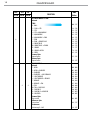
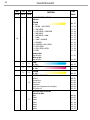
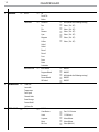
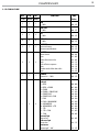
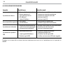
3.15 CANALI DMX
BAS STD EXT
FUNCTION DMX
Value
21 Ch 24 Ch 26Ch
1 1 1
PAN
0~100% 000 - 255
2 2 2
PAN 16bit
0~100% 000 - 255
3 3 3
TILT
0~100% 000 - 255
4 4 4
TILT 16bit
0~100% 000 - 255
5 5 5
P/T SPEED
Fastest to slowest
Movement with blackout
000 - 247
248 - 255
6 6 6
SHUTTER
Shutter closed
Open
Strobe eect slow to fast
Open
Pulse-eect in sequences
Open
Random strobe eect slow to fast
Open
000 - 031
032 - 063
064 - 095
096 - 127
128 - 159
160 - 191
192 - 223
224 - 255
7 7 7
DIMMER
Dimmer 0% ~ 100% 000 - 255
- 8 8
COLOR WHEEL 1
Indexed
1 - OPEN
2 - OPEN + CONGO
3 - CONGO
4 - CONGO + COBALT BLUE
5 - COBALT BLUE
6 - COBALT BLUE + PINK
7 - PINK
8 - PINK + AQUAMARINE
9 - AQUAMARINE
10 - AQUAMARINE + CTB
11 - CTB
12 - CTB + CYAN
13 - CYAN
Forward Spin
Slow to fast
& Reverse Spin
Fast to slow
Continuous
Positioning 0°~360°
000 - 004
005 - 009
010 - 014
015 - 019
020 - 024
025 - 029
030 - 034
035 - 039
040 - 044
045 - 049
050 - 054
055 - 059
060 - 063
064 - 095
096 - 127
128 - 255

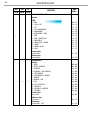
RAZOR440
18
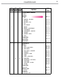
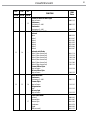
BAS STD EXT
FUNCTION
DMX
Value
21 Ch 24 Ch 26Ch
8
1st COLOR WHEEL & CYAN
Indexed
CYAN
0~100%
000 - 127
2 - CYAN + CTB
3 - CTB
4 - CTB + AQUAMARINE
5 - AQUAMARINE
6 - AQUAMARINE + PINK
7 - PINK
8 - PINK + COBALT BLUE
9 - COBALT BLUE
10 - COBALT BLUE + CONGO
11 - CONGO
12 - CONGO + OPEN
13 - OPEN
Forward Spin
Stop to fastest
Reverse Spin
Stop to fastest
128 - 132
133 - 137
138 - 142
143 - 147
148 - 152
153 - 157
158 - 162
163 - 167
168 - 173
173 - 177
178 - 182
183 - 191
192 - 223
224 - 255
- 9 9
COLOR WHEEL 2
Indexed
1 - OPEN
2 - OPEN + DARK RED
3 - DARK RED
4 - DARK RED + LIGHT ORANGE
5 - LIGHT ORANGE
6 - LIGHT ORANGE + ORANGE
7 - ORANGE
8 - ORANGE + TAN
9 - TAN
10 - TAN + PALE ROSE
11 - PALE ROSE
12 - PALE ROSE + MAGENTA
13 - MAGENTA
Forward Spin
Slow to fast
& Reverse Spin
Fast to slow
Continuous
Positioning 0°~360°
000 - 004
005 - 009
010 - 014
015 - 019
020 - 024
025 - 029
030 - 034
035 - 039
040 - 044
045 - 049
050 - 054
055 - 059
060 - 063
064 - 095
096 - 127
128 - 255
La pagina sta caricando ...
La pagina sta caricando ...
La pagina sta caricando ...
La pagina sta caricando ...
La pagina sta caricando ...
La pagina sta caricando ...
La pagina sta caricando ...
La pagina sta caricando ...
La pagina sta caricando ...
La pagina sta caricando ...
La pagina sta caricando ...
La pagina sta caricando ...
La pagina sta caricando ...
La pagina sta caricando ...
La pagina sta caricando ...
La pagina sta caricando ...
La pagina sta caricando ...
La pagina sta caricando ...
La pagina sta caricando ...
La pagina sta caricando ...
La pagina sta caricando ...
La pagina sta caricando ...
La pagina sta caricando ...
La pagina sta caricando ...
La pagina sta caricando ...
La pagina sta caricando ...
La pagina sta caricando ...
La pagina sta caricando ...
La pagina sta caricando ...
La pagina sta caricando ...
La pagina sta caricando ...
La pagina sta caricando ...
La pagina sta caricando ...
La pagina sta caricando ...
La pagina sta caricando ...
La pagina sta caricando ...
La pagina sta caricando ...
La pagina sta caricando ...
La pagina sta caricando ...
La pagina sta caricando ...
La pagina sta caricando ...
La pagina sta caricando ...
La pagina sta caricando ...
La pagina sta caricando ...
La pagina sta caricando ...
La pagina sta caricando ...
La pagina sta caricando ...
La pagina sta caricando ...
La pagina sta caricando ...
La pagina sta caricando ...
La pagina sta caricando ...
La pagina sta caricando ...
-
 1
1
-
 2
2
-
 3
3
-
 4
4
-
 5
5
-
 6
6
-
 7
7
-
 8
8
-
 9
9
-
 10
10
-
 11
11
-
 12
12
-
 13
13
-
 14
14
-
 15
15
-
 16
16
-
 17
17
-
 18
18
-
 19
19
-
 20
20
-
 21
21
-
 22
22
-
 23
23
-
 24
24
-
 25
25
-
 26
26
-
 27
27
-
 28
28
-
 29
29
-
 30
30
-
 31
31
-
 32
32
-
 33
33
-
 34
34
-
 35
35
-
 36
36
-
 37
37
-
 38
38
-
 39
39
-
 40
40
-
 41
41
-
 42
42
-
 43
43
-
 44
44
-
 45
45
-
 46
46
-
 47
47
-
 48
48
-
 49
49
-
 50
50
-
 51
51
-
 52
52
-
 53
53
-
 54
54
-
 55
55
-
 56
56
-
 57
57
-
 58
58
-
 59
59
-
 60
60
-
 61
61
-
 62
62
-
 63
63
-
 64
64
-
 65
65
-
 66
66
-
 67
67
-
 68
68
-
 69
69
-
 70
70
-
 71
71
-
 72
72


ProLights RAZOR440 Manuale utente
- Categoria
- Proiettori
- Tipo
- Manuale utente
in altre lingue
- English: ProLights RAZOR440 User manual
Documenti correlati
-
ProLights RAZOR440 Manuale utente
-
-
-
-
-
-
-
-
-
Altri documenti
-
CHAUVET DJ Gobozap 2x90w LED In-Air Gobo Sweeping Lighting Effect Guida utente
-
Clay Paky C61700 C61701 Manuale utente
-
Sagitter SG AQUFLEX7Z Manuale utente
-
PROEL PLML575E Manuale utente
-
-
-
SDJ SG JBEAM230KIT Manuale utente
-
-
-
Griven ACROBAT PE 575 Owners Manual & Instruction