
SC.P30QIS
SC.P30QES
L8542339
Rev. 11/07/01
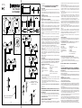
40-60cm
Fig.1
Fig.2
1
2
1
2
3
5
4
+
+
-
24Vac-Vdc
C
NO NC
TX
RX
+
24Vac-Vdc
+
-
COM
NO
NC
3
4
5
Fig.3
Fig.5 Fig.6
COM
COM
Power
OFF
NO
NO
NC
NC
4
3
5
3
5
4
LED
A
B
JP2 Open
SYNC OFF
SYNC
JP2 Open
SYNC OFF
SYNC
Fig.4
+
-
C
NO NC
+
-
JP2 Close
SYNC ON
SYNC
JP2 Close
SYNC ON
SYNC
TX1 RX1
+
-
C
NO NC
+
-
JP2 Close
SYNC ON
SYNC
JP2 Close
SYNC ON
SYNC
TX2 RX2
24 Vac
+
-
C
NO NC
+
-
JP2 Close
SYNC ON
SYNC
JP2 Close
SYNC ON
SYNC
TX1 RX1
+
-
C
NO NC
+
-
JP2 Close
SYNC ON
SYNC
JP2 Close
SYNC ON
SYNC
TX2 RX2
24 Vac
+
-
C
NO NC
+
-
JP2 Close
SYNC ON
SYNC
JP2 Close
SYNC ON
SYNC
TX3 RX3
+
-
C
NO NC
+
-
JP2 Close
SYNC ON
SYNC
JP2 Close
SYNC ON
SYNC
TX4 RX4
TX1
TX2
RX1
RX2
TX1
TX2
RX1
RX2
RX3
RX4
TX3
TX4
ITALIANO
FOTODISPOSITIVI DA INCASSO E DA ESTERNO A
LUCE MODULATA CON DUE RELE’
DESCRIZIONE
Fotodispositivo costituito da un ricevitore e da un trasmettitore a luce
infrarossa modulata.
Il corretto allineamento della coppia trasmettitore-ricevitore viene visua-
lizzato da un led sul ricevitore: è quindi possibile una facile e accurata
installazione.
POSSIBILITA’ DI IMPIEGO
Viene impiegato per la protezione di porte, cancelli e accessi automatizzati
in genere.
INSTALLAZIONE E ALLINEAMENTO
1) Murare o ssare con le apposite quattro viti il contenitore dei dispositivi,
tenendo conto che per una corretta installazione il trasmettitore e il rice-
vitore devono essere montati in posizione frontale e allineati sullo stesso
asse (g. 1).
2) Far passare i cavi di collegamento attraverso il contenitore e collegarli
alle rispettive morsettiere del trasmettitore e del ricevitore (gura 2), preoc-
cupandosi che i cavi siano più corti possibile, evitando di farli passare
nelle vicinanze di potenziali fonti di disturbo (es. motori ) e possibilmente
montando il ricevitore vicino alla centralina.
3) Inserire nel contenitore la parte ottico/elettronica e ssarla con le ap-
posite viti.
4) Alimentare i fotodispositivi alla tensione di alimentazione di 24Vdc o
24Vac.
Se il collegamento è stato effettuato correttamente si accenderà il led ros-
so sul ricevitore e il contatto NC (morsetti 3 e 5 del ricevitore) sarà chiuso.
La g.3 esemplica i due possibili stati dei contatti delle uscite relè.
5) Nel caso che la distanza di lavoro sia contenute (inferiore a circa 5-8 me-
tri) o quando ci sono parti riettenti vicine che possono disturbare il corret-
to funzionamento del sistema, inserire il dischetto attenuatore (Fig.4- A) in
gomma nella sede posta davanti alla lente del ricevitore. Il disco attenuato-
re può risultare utile anche per la schermatura da raggi solari.
6) Regolare la centratura del fascio agendo sulle apposite viti poste a
triangolo (Fig.4-B), in modo tale che il led rosso del ricevitore rimanga
sempre acceso.
7) Vericare il funzionamento del sistema, interrompendo più volte il raggio
infrarosso frapponendo un ostacolo tra il trasmettitore e il ricevitore; con-
trollare la conseguente commutazione dei relè e lo spegnimento del led
rosso sul ricevitore.
8) Montare ad incastro i frontalini di protezione e ricontrollare il funziona-
mento del sistema.
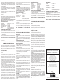
SINCRONISMO
Per evitare interferenze nel caso di utilizzo di due coppie di fotocellule ravvi-
cinate, attivare il sincronismo chiudendo i jumper JP2 sia sui trasmettitori sia
sui ricevitori. Il sincronismo funziona esclusivamente con alimentazione
24Vac con polarità invertita tra le due coppie come indicato in Fig. 5/6.
CARATTERISTICHE TECNICHE:
Alimentazione: 24Vac/Vdc +/-15%
Contatti relè: 1A MAX. a 24Vcc / 0.5A a 120Vca
Temp.di funzionamento: -10C°/+65C°
Assorbimento ricevitore: 40mA MAX
Assorbimento trasmettitore: 50mA MAX
Portata: 30 metri (senza disco attenuatore)
15 metri (con disco attenuatore
NOTE D’USO E AVVERTENZE:
• L’utilizzo del dischetto attenuatore comporta una riduzione di portata
pari a circa il 40%
• Al termine dell’installazione vericare il corretto funzionamento del di-
spositivo in modo da non creare pericolo a persone o cose.
• In caso di pioggia, nebbia o polvere la portata del fotodispositivo può
diminuire no al 50%.
N.B.: PRODOTTO ADATTO ALLA SOLA APPLICAZIONE APRICANCELLO.
ENGLISH
EMBEDDED PHOTODEVICES AND PHOTOCELLS FOR OU-
TDOOR USE WITH MODULATED LIGHT AND TWO RELAYS
DESCRIPTION
Photocell made of a receiver and a modulated infrared light transmitter.
The correct alignment of the transmitter-receiver pair is shown through a
LED on the receiver, thus ensuring an easy and accurate installation.
POSSIBILITY OF USE
It is used to protect doors, gates and automated accesses in general.
INSTALLATION AND ALIGNMENT
1) Embed the device container into the wall or x it by means of the special
four screws. It should be kept in mind that, for a correct installation, the
transmitter and the receiver must be assembled one in front of the other or
aligned on the same axis.
2) Insert the connecting cables through the container and connect them
to the relevant terminal strips of the transmitter and the receiver (gure 2).
The cables should be as short as possible, avoiding to make them run near
interference sources (e.g. motors). Possibly assemble the receiver near
the control unit.
3) Insert the optical/electronic element in the container and t it by means
of the special screws.
4) Power the photocells at a power voltage of 24VDC or “24VAC. If the
connection has been correctly carried out, the red LED on the receiver
switches on and the NC contact (terminals 3 and 5 on the receiver) is clo-
sed. Figure 3 shows two possible status of the relay output contacts.
5) Should the working distance be reduced (lower than approx. 5-8 me-
tres) or if reecting elements are near which might interfere with the correct
operation of the system, insert the dimming rubber disc (Fig.4- A) in the
hollow in front of the receiver lens. The dimming disc can be useful also to
protect the unit from direct sunlight.
6) Adjust the correct centring of the beam by using the special screws
places in a triangle, (Fig.4-B) so that the red LED of the receiver stays
always on.
7) Check the correct operation of the system by placing an obstacle
between the transmitter and the receiver various times, thus causing the
interruption of the infrared beam; check that, as a consequence of this, the
relay triggers and the red LED on the receiver switches off.
8) Clip the protection aps on the unit and check the correct operation of
the system.
SYNCHRONIZATION
To avert any interference when using two pairs of photocells mounted close
together, activate the synchronization function by closing the jumpers J2 on
both transmitters and receivers.
The synchronization operates only with 24Vac power supply and re-
versed polarity between the two pairs, as shown in Fig. 5/6.
SPECIFICATIONS
Power supply: 24Vac/Vdc +/-15%
Relay contacts: 1A MAX. a 24Vcc / 0.5A a 120Vca
Operating temperature: -10C°/+65C°
Receiver absorption: 40mA MAX
Transmitter absorption: 50mA MAX
Range: 30 m (without dimming disc)
15 m (with dimming disc).
INSTRUCTIONS FOR USE AND WARNING NOTES
• The use of the dimming disc causes a range reduction of about 40%.
• At completion of the installation, check the correct operation of the de-
vice, in order to avert any hazard to people or objects.
• In the event of rain, fog or dust, the photocell range may reduce up to
50%.
N.B. THIS ITEM IS SUITED TO ONLY OPEN THE GATE
DEUTSCH
FOTOZELLENEINRICHTUNG FÜR UP- ODER WANDAU-
SFÜHRUNG MIT LICHTMODULATION MIT ZWEI RELAIS
BESCHREIBUNG
Die Fotozelleneinheit besteht aus einem Empfänger und einem Sender mit
infraroter Lichtmodulation.
Die richtige Ausrichtung des Senders und des Empfängers wird durch eine
Leuchte am Empfänger gemeldet: dadurch wird die Installation erheblich
vereinfacht.
ANWENDUNGSMÖGLICHKEITEN
Die Einheit wird zum Schutz von Türen, Toren und allgemein für motorge-
steuerte Vorrichtungen verwendet.
INSTALLATION UND AUSRICHTUNG
1) Die Einheit einmauern oder mit den entsprechenden vier Schrauben
den Kasten der Einheit befestigen. Zur einwandfreien Installation müssen
der Sender und der Empfänger frontal montiert und auf derselben Achse
ausgerichtet sein.
2) Die Verbindungskabel durch den Kasten führen und an die entsprechen-
den Klemmleisten des Senders und des Empfängers schließen (Abbildung
2). Dabei sollten die Kabel so kurz wir möglich sein und nicht in der Nähe
von Störungsquellen verlegt werden (z.B. Motoren). Der Empfänger sollte
so nahe wie möglich neben der Einheit montiert werden.
3) In den Kasten das optische/elektronische Teil einsetzen und mit den
entsprechenden Schrauben befestigen.
4) Die Fotozelleneinrichtung mit einer Speisespannung von 24VDC oder
24VAC speisen. Wenn die Einrichtung richtig angeschlossen worden ist,
leuchtet die rote Leuchte am Empfänger auf und der Ruhekontakt (NC)
(Klemmen 3 und 5 des Empfängers) bleibt geschlossen. Die Abbildung 3
zeigt die zwei möglichen Zustände der Kontakte der Relaisausgänge.
5) Falls der Betriebszustand beschränkt ist (weniger als 5-8 Meter beträgt)
2 coppie - 2 pairs - 2 fotozellenpaare
2 couples - 2 paejas - 2 par
2+2 coppie - 2+2 pairs
2+2 fotozellenpaare - 2+2 couples
2+2 paejas - 2+2 par
La pagina si sta caricando...
-
 1
1
-
 2
2


in altre lingue
- English: Beninca SCP30QIS/SCP30QES User guide
- français: Beninca SCP30QIS/SCP30QES Mode d'emploi
- español: Beninca SCP30QIS/SCP30QES Guía del usuario
- Deutsch: Beninca SCP30QIS/SCP30QES Benutzerhandbuch
- polski: Beninca SCP30QIS/SCP30QES instrukcja
Documenti correlati


Altri documenti
-
Nice Automation FT210 Manuale del proprietario
-
PRASTEL FOTO35SDE Manuale utente
-
BFT Rigel5 Manuale del proprietario
-
 KINGgates Viky 11 Manuale del proprietario
-
Marantec LS22 Manuale del proprietario
-
 Roger Technology M90/F4ES0 Guida d'installazione
-
Ducati CTR34 Manuale del proprietario
-
-
Genius POLARIS Istruzioni per l'uso
-

