La pagina si sta caricando...

L8542633 Rev. 10/06/01
PUPILLA
Con la presente dichiariamo che il nostro prodotto
We hereby declare that our product
Hiermit erklaren wir, dass unser Produkt
Nous déclarons par la présente que notre produit
Por la presente declaramos que nuestro producto
Niniejszym oświadczamy że nasz produkt
PUPILLA
è conforme alle seguenti disposizioni pertinenti:
complies with the following relevant provisions:
folgenden einschlagigen Bestimmungen entspricht:
correspond aux dispositions pertinentes suivantes:
satisface las disposiciones pertinentes siguientes:
zgodny jest z poniżej wyszczególnionymi
rozporządzeniami:
89/336/CEE, 93/68/CEE
05/10/2006
Data/Firma
Dichiarazione CE di conformità
EC declaration of conrmity
EG-Konformitatserklarung
Déclaration CE de conformité
Declaracion CE de conformidad
Deklaracja UE o zgodności
AUTOMATISMI BENINCÀ SpA
Via Capitello, 45 - 36066 Sandrigo (VI)
Tel. 0444 751030 r.a. - Fax 0444 759728
Fotocellula rotante 180° da parete
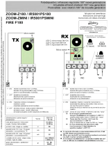
Apertura fotocellula
Fare leva nella parte inferiore centrale come indi-
cato nella Fig.A.
Fissaggio (fig.B)
A Fondo
B Viti fissaggio a parete
C Circuito stampato
D Supporto per circuito stampato
E Viti fissaggio blocco rotazione
F Blocco rotazione
G Predisposizione passaggio cavi
Caratteristiche Tecniche
Alimentazione 22÷30Vac o 20÷28Vdc
Portata 20-25 m
Grado di protezione IP 44
Temperatura funzion. -20°C/+70°C
Assorbimento TX 20mA
Assorbimento RX 50mA
Collegamento (fig.C)
TX M1: 24Vac (+24Vdc)
M2: 24Vac (-24Vdc)
RX M1: 24Vac (+24Vdc)
M2: 24Vac (-24Vdc)
M3: Comune, COM.
M4: Contatto normalmente aperto, N.O.
M5: Contatto normalmente chiuso, N.C.*
*Con fotocellule alimentate e allineate.
Regolazione del centraggio
La regolazione del centraggio della fotocellula si
effettua allentando le viti E.
Il LED indica il livello di ricezione:
Lampeggio del LED lento: ricezione debole
Lampeggio del LED veloce: ricezione buona
LED acceso: ricezione ottimale.
Sincronismo
Per evitare interferenze nel caso di utilizzo di due
coppie di fotocellule ravvicinate, attivare il sincroni-
smo chiudendo i jumper JP2 sia sui trasmettitori sia
sui ricevitori. Il sincronismo funziona esclusiva-
mente con alimentazione 24Vac con polarità inver-
tita tra le due coppie come indicato in Fig. D/E.
Rotating photocell, 180°, fitting to wall
Opening of the photocell
Lift the cover be levering at the center of the lower
part, as shown in Fig. A
Fitting (fig.B)
A Bottom
B Wall fitting screws
C Printed circuit
D Support for printed circuit
E Fitting screws, rotation lock
F Rotation lock
G Presetting for the passage of cables
Specifications
Power supply 22÷30Vac or 20÷28Vdc
Range 20-25 m
Protection level IP 44
Oper. temperature -20°C/+70°C
Consumption TX 20mA
Consumption RX 50mA
Wire connections (fig. C)
TX M1: 24Vac (+24Vdc)
M2: 24Vac (-24Vdc)
RX M1: 24Vac (+24Vdc)
M2: 24Vac (-24Vdc)
M3: Common, COM.
M4: Normally open contact, N.O.
M5: Normally closed contact, N.C.*
*With powered and aligned photocells.
Adjustment of the alignment
The photocells are aligned by loosening the screws
E. As regards the reception LED:
LED flashes slowly: scarce reception
LED flashes quickly: good reception
LED on: optimal reception.
Synchronization
To avert any interference when using two pairs of
photocells mounted close together, activate the
synchronization function by closing the jumpers
J2 on both transmitters and receivers.
The synchronization operates only with 24Vac
power supply and reversed polarity between the
two pairs, as shown in Fig. D/E.
Um 180° schwenkbare Fotozelle
für die Wandmontage
Öffnen der Fotozelle
Den unteren Teil der Einheit anheben wie in der
Abb. A gezeigt.
Befestigung (Abb. B)
A Boden
B Wandbefestigungsschrauben
C Platine
D Platinenhalterung
E Befestigungsschrauben
F Schwenkbarer Block
G Kabeldurchführung
Technische Eigenschaften
Speisung 22÷30Vac oder 20÷28Vdc
Tragweite 20-25 m
Schutzklasse IP 44
Betriebstemperatur -20°C/+70°C
Stromaufnahme TX: 20mA
Stromaufnahme RX: 50mA
Anschluss (Abb. C)
TX M1: 24Vac (+24Vdc)
M2: 24Vac (-24Vdc)
RX M1: 24Vac (+24Vdc)
M2: 24Vac (-24Vdc)
M3: Gemein, COM.
M4: Arbeitskontakt, N.O.
M5: Ruhekontakt, N.C.*
*Bei gespeisten und angereihten Fotozellen
Regelung der Zentrierung
Die Regelung der Zentrierung der Fotozelle erfolgt
durch Lockern der Schrauben E.
Die LED zeigt das Empfangsniveau an:
LED blinkt langsam: schwacher Empfang
LED blinkt schnell: guter Empfang
LED ein: optimaler Empfang
Synchronismus
Falls zwei nahliegende Fotozellenpaare verwendet
werden, den Synchronismus aktivieren, um Störun-
gen zu vermeiden. Dazu die Jumpers JP2 an den
Sendegeräten und an den Empfängern schließen.
Der Synchronismus funktioniert ausschließlich
mit einem Netzgerät 24Vac mit umgetauschten
Polenpaaren, wie in Abb. D/E gezeigt.
Photocellule tournante 180° à paroi
Ouverture photocellule
Faire pression sur la partie inférieure centrale comme
indiqué dans la Fig.A
Fixage (Fig.B)
A Fond
B Vis de fixage à paroi
C Circuit imprimé
D Support pour circuit imprimé
E Vis de fixage système de rotation
F Système de rotation
G Prédisposition passage des câbles
Caracteristiques Tecniques
Alimentation 22÷30Vac ou 20÷28Vdc
Débit 20-25 m
Degré de protection IP 44
Température fonct. -20°C/+70°C
Absorption TX 20mA
Absorption RX 50mA
Branchement (Fig.C)
TX M1: 24Vac (+24Vdc)
M2: 24Vac (-24Vdc)
RX M1: 24Vac (+24Vdc)
M2: 24Vac (-24Vdc)
M3: Commune, COM.
M4: Contact normalement ouvert, N.O.
M5: Contact normalement fermé, N.F.*
*Avec photocellules alimentées et alignées.
Réglage du centrage
Le réglage du centrage de la photocellule a lieu
en desserrant les vis E. Le LED indique le niveau
de réception:
Clignotement du LED lent: réception faible
Clignotement du LED rapide: bonne réception
LED allumé: réception optimale.
Synchronisme
A fin d’éviter toute interférence en cas d’utilisation
de deux couples de photocellules rapprochées, ac-
tivez le synchronisme en fermant les jumpers JP2
soit sur les transmetteurs, soit sur les récepteurs.
Le synchronisme marche exclusivement avec
alimentation 24Vac avec polarité inverse entre les
deux couplet comme indiqué dans la in Fig. D/E.
Fotocélula giratoria 180° para pared
Apertura fotocélula
Hacer palanca en la parte inferior central, como
mostrado en la Fig.A
Fijación (fig.B)
A Fondo
B Tornillos de fijación en pared
C Circuito impreso
D Soporte para circuito impreso
E Tornillos de fijación del bloque rotación
F Bloque Rotación
G Preparación para el paso de cables
Características Técnicas
Alimentación 22÷30Vac o 20÷28Vdc
Alcance 20-25 m
Grado de protección IP 44
Temperatura funcion. -20°C/+70°C
Absorción TX 20mA
Absorción RX 50mA
Conexión (Fig.c)
TX M1: 24Vac (+24Vdc)
M2: 24Vac (-24Vdc)
RX M1: 24Vac (+24Vdc)
M2: 24Vac (-24Vdc)
M3: Común, COM.
M4: Contacto normalmente abierto, N.O.
M5: Contacto normalmente cerrado, N.C.*
*Con fotocélulas alimentadas y alineadas.
Ajuste del centrado
El ajuste del centrado de la fotocélula se realiza
aflojando los tornillos E. El LED indica el nivel de
recepción:
Parpadeo lento del LED: recepción débil
Parpadeo rápido del LED: recepción buena
LED encendido fijo: recepción óptima.
Sincronismo
Para evitar interferencias, si se utilizan dos parejas de
fotocélulas cercanas, activar el sincronismo cerrando
los puentes JP2 tanto en los transmisores como en los
receptores. El sincronismo funciona exclusivamente
con alimentación de 24Vac, con polaridad invertida
entre las dos parejas, como mostrado en la Fig. D/E.
Fotokomórka obrotowa 180°
mocowana na ścianie
Otwarcie fotokomórki
Podważyć w środkowej części dolnej tak, jak wskaza-
no na Rys.A.
Umocowanie (rys.B)
A Dno
B Śruby mocowania do ściany
C Obwód drukowany
D Uchwyt obwodu drukowanego
E Śruby mocowania blokady obrotu
F Blokada obrotu
G Przygotowanie przejścia przewodów
Dane Techniczne
Zasilanie 22÷30Vac lub 20÷28Vdc
Zasięg 20-25 m
Stopień zabezpieczenia IP 44
Temperatura działania -20°C/+70°C
Pochłanianie TX 20mA
Pochłanianie RX 50mA
Połączenia (rys.C)
TX M1: 24Vac (+24Vdc)
M2: 24Vac (-24Vdc)
RX M1: 24Vac (+24Vdc)
M2: 24Vac (-24Vdc)
M3: Wspólny, COM.
M4: Zestyk normalnie otwarty, N.O.
M5: Zestyk normalnie zwarty, N.C.*
*Przy fotokomórkach zasilanych i uliniowanych.
Regulacja środkowania
Regulacji środkowania fotokomórki dokonuje się
przez poluzowanie śrub E. LED wskazuje poziom
odbioru:
Błyskanie LEDu wolne: odbiór słaby
Błyskanie LEDu szybkie: odbiór dobry
LED świeci się: odbiór optymalny.
Synchronizm
W celu uniknięcia zakłóceń w przypadku używania
dwu par fotokomórek znajdujących się blisko siebie
należy uaktywnić funkcję synchronizmu poprzez
zamknięcie jumperów JP2 zarówno w nadajnikach,
jak i w odbiornikach. Synchronizm działa wyłącznie
przy zasilaniu na 24Vac przy biegunowości od-
wróconej między obiema parami tak, jak wskazano
na Rys. D/E.
1/2