La pagina si sta caricando...

USER MANUAL
MANUALE UTENTE
LUMIPAR7IP
EN - IT
SUPER-SLIM PARLED

All rights reserved by Music & Lights S.r.l. No part of this instruction manual may be
reproduced in any form or by any means for any commercial use.
In order to improve the quality of products, Music&Lights S.r.l. reserves the right to modify the
characteristics stated in this instruction manual at any time and without prior notice.
All revisions and updates are available in the ‘manuals’ section on site www.musiclights.it
REV.001-09/17

Packing content
• LUMIPAR7IP
• Mount bracket
• Power cable
• User manual
TABLE OF CONTENTS
Safety
General instructions
Warnings and installation precautions
1 Introduction
1. 1 Description
1. 2 Technical specifications
1. 3 Operating elements and connections
2 Installation
2. 1 Mounting
3 Functions and settings
3. 1 Operation
3. 2 Basic
3. 3 Menu structure
3. 4 DMX Mode
3. 5 DMX configuration
3. 6 Linking
3. 7 DMX Addressing
3. 8 Settings
Screen
3. 9 Fixture Settings
Dimmer
White Calibration
LED Frequency
Factory Reload
3. 10 Fixture Information
3. 11 Operations in automatic mode
Master/Slave
Effects
Static Mode
3. 12 Connection of the DMX line
3. 13 Construction of the DMX termination
3. 14 DMX control
4 Maintenance
4. 1 Maintenance and cleaning the unit
4. 2 Fuse replacement
4. 3 Troubleshooting
2
2
3
3
5
6
7
7
8
9
9
9
9
10
10
10
10
11
11
11
11
11
11
11
12
13
13
14
15
15
15

LUMIPAR7IP
2
WARNING! Before carrying out any operations with the unit, carefully read this instruction
manual and keep it with cure for future reference. It contains important information about
the installation, usage and maintenance of the unit.
SAFETY
General instruction
• The products referred to in this manual conform to the European Community Directives and are there-
fore marked with .
• The unit is supplied with hazardous network voltage (230V~). Leave servicing to skilled personnel only.
Never make any modifications on the unit not described in this instruction manual, otherwise you will
risk an electric shock.
• Connection must be made to a power supply system fitted with efficient earthing (Class I appliance ac-
cording to standard EN 60598-1). It is, moreover, recommended to protect the supply lines of the units
from indirect contact and/or shorting to earth by using appropriately sized residual current devices.
• The connection to the main network of electric distribution must be carried out by a qualified electrical
installer. Check that the main frequency and voltage correspond to those for which the unit is designed
as given on the electrical data label.
• This unit is not for home use, only professional applications.
• Never use the fixture under the following conditions:
- in places subject to vibrations or bumps;
- in places with a temperature of over 45 °C.
• Make certain that no inflammable liquids, water or metal objects enter the fixture.
• Do not dismantle or modify the fixture.
• All work must always be carried out by qualified technical personnel. Contact the nearest sales point for
an inspection or contact the manufacturer directly.
• If the unit is to be put out of operation definitively, take it to a local recycling
plant for a disposal which is not harmful to the environment.
Warnings and installation precautions
• If this device will be operated in any way different to the one described in this manual, it may suffer
damage and the guarantee becomes void. Furthermore, any other operation may lead to dangers like
short circuit, burns, electric shock, etc.
• Before starting any maintenance work or cleaning the projector, cut off power from the main supply.
• Always additionally secure the projector with the safety rope. When carrying out any work, always com-
ply scrupulously with all the regulations (particularly regarding safety) currently in force in the country
in which the fixture’s being used.
• Install the fixture in a well ventilated place.
• Keep any inflammable material at a safe distance from the fixture.
• Shields, lenses or ultraviolet screens shall be changed if they have become damaged to such an extent
that their effectiveness is impaired.
• The lamp (LED) shall be changed if it has become damaged or thermally deformed.
• Never look directly at the light beam. Please note that fast changes in lighting, e. g. flashing light, may
trigger epileptic seizures in photosensitive persons or persons with epilepsy.
• Do not touch the product’s housing when operating because it may be very hot.
• This product was designed and built strictly for the use indicated in this documentation. Any other use,
not expressly indicated here, could compromise the good condition/operation of the product and/or
be a source of danger.
• We decline any liability deriving from improper use of the product.

3
LUMIPAR7IP
- 1 - INTRODUCTION
1.1 DESCRIPTION
LUMIPAR7IP is a compact and flexible IP LED PAR Can made for small concerts and theatres, and to perform
as architectural accent luminaire for outdoor events. The housing in die-cast aluminium is designed to
feature both as a robust workhorse and totally fan-free being totally silent during its operation.
1.2 TECHNICAL SPECIFICATIONS
LIGHT SOURCE
• Source: 7x9W RGBW LEDs
• Luminous flux: 20°: 2’945 lm - 45°: 3’835lm
• Lux: (20°) 1’923lx @3 m full
• Lux: (45°) 654lx @3 m full
• Source life expectancy: >50.000 h
OPTICS
• Beam angle: available in 20° or 45°
• Field angle: 36° or 60°
COLOUR SYSTEM
• Colour mixing: RGBW / FC
• White presets: 3.000 K ~ 10.000K
• Colour wheel: virtual colour wheel with presets
• Macros: built-in white presets
DYNAMIC EFFECTS
• Static colour mode: selection of static colour
• Manual colour mode: manual adjustment of colour
• Auto mode: built-in programs with execution speed adjustment
BODY
• Body: sturdy die-cast aluminium body conceived for long-time durability
• Body colour: black
CONTROL
• Protocols: DMX512
• DMX channels: 4 / 6 / 11channel
• Display: black OLED touch display
• Firmware upgrade: yes, via USB - DMX interface (UPBOX1) not included
• Master/Slave: for synchronized operation of more units linked in a chain
ELECTRONICS
• Dimmer: linear 0 ~ 100% electronic dimmer
• Dimmer curves: 4 different dimming curves available
• Strobe / shutter: 0 - 30 Hz, electronic
• Operating temperature: -20° ~ +45°
• Flicker: flicker free operation
• Selectable PWM: 600 ~ 25.000 Hz

LUMIPAR7IP
4
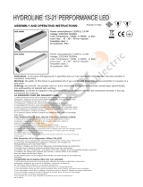
Technical drawing Fig.1
240
154
175
286
ELECTRICAL
• Power supply: 100-240 V – 50/60 Hz
• Power consumption (at 230 V): 65W
• Power consumption (at 120 V): 64W
• Output (at 230 V): 58 units on a single power line
• Output (at 120 V): 31 units on a single power line
PHYSICAL
• Cooling: natural cooling of the peculiar chassis and to absence of fans
• Sospension and fixing: double hanging bracket suitable for safe hanging and for floor positioning
• Signal connection: Seetronic XLR 5p IN/OUT connectors
• Power connection: Seetronic powerCON waterproof IN/OUT connectors
• IP rating: 65 for outdoor installations
• Dimensions (WxHxD): 240x286x154mm
• Weight: 3,64kg

5
LUMIPAR7IP
1.3 OPERATING ELEMENTS AND CONNECTIONS
Fig.2 - Rear panel
1. MOUNTING BRACKET.
2. LOCKING KNOB for the mounting bracket.
3. CONTROL PANEL with display and 4 button
used to access the control panel functions
and manage them.
4. SAFETY EYE to attach safety cable.
5. POWER IN (PowerCON IN): for connection to a
socket (100-240V~/50-60Hz) via the supplied
mains cable.
6. DMX IN (5-pole XLR): 1 = ground, 2 = DMX-, 3
= DMX+, 4 N/C, 5 N/C.
7. GND POINT grounding the fixture to the earth.
8. DMX OUT (5-pole XLR): 1 = ground, 2 = DMX-,
3 = DMX+, 4 N/C, 5 N/C.
9. POWER OUT: connect to supply power to the
next unit.
1
2
3
7
5 9
64 8

LUMIPAR7IP
6
- 2 - INSTALLATION
2.1 MOUNTING
LUMIPAR7IP may be set up on a solid and even surface. The unit can also be mounted upside down to a
cross arm. For fixing, stable mounting clips are required. The mounting place must be of sufficient stability
and be able to support a weight of 10 times of the unit’s weight.
When carrying out any installation, always comply scrupulously with all the regulations (particularly re-
garding safety) currently in force in the country in which the fixture’s being used.
• Install the projector at a suitable location by means of the mounting bracket (1).
• Always additionally secure the projector with the safety rope from falling down. For this purpose, fas-
ten the safety rope at a suitable position so that the maximum fall of the projector will be 20 cm.
• Adjust the projector and use the knob (2) to slightly release or tighten the locking mechanism of the
bracket if is necessary.
Fig.3
2
1

7
LUMIPAR7IP
Fig.4 - Functions of the buttons
- 3 - FUNCTIONS AND SETTINGS
3.1 OPERATION
Connect the supplied main cable to a socket (100-240 VAC-50/60 Hz). Then the unit is ready for operation
and can be operated via a DMX controller or it independently performs its show program in succession.
To switch off, disconnect the mains plug from the socket. For a more convenient operation it is recom-
mended to connect the unit to a socket which can be switched on and off via a light switch.
3.2 BASIC
Access control panel functions using the four panel buttons located directly underneath the LED Display
(fig.4).
MENU UP DOWN ENTER
Used to access the menu or
to return a previous menu
option
Navigates downwards through
the menu list and increases
the numeric value when in a
function
Navigates upwards through
the menu list and decreases
the numeric value when in
a function
Used to select and store the
current menu or confirm the
current function value or
option within a menu

LUMIPAR7IP
8
3.3 MENU STRUCTURE
MENU
1 CONNECT
ð
DMX Address
ð
Value (001-512)
DMX Mode
ð
Easy 4CH
Basic 6CH
Standard 11CH
2 SETUP
ð
Screen
ð
Back Light
ð
On
10S
20S
30S
ð
Key Lock
ð
NO-Yes
3 ADVANCED
ð
Dimmer Mode
ð
Off
Dimmer 1
Dimmer 2
Dimmer 3
White Balance
ð
Off
ð
Adjust Red <125-255>
Green <125-255>
Blue <125-255>
White <125-255>
Led Frequency
ð
600Hz
1200 Hz
2000 Hz
4000 Hz
6000Hz
25kHZ
Factory Reload
ð
NO-Yes
4 INFORMATION
ð
Fixture TIme
ð
0-9999
Version
ð
V1.0
4 STAND ALONE
ð
Maser/Slave
ð
15D00217****
ð
Effects
ð
Effect1
……
Effect5
ð
Static
ð
Fixed Color
ð
R
G
B
W
GB
RB
RG
RGB
RW
GW
BW
RGW
RBW
GBW
RGBW

9
LUMIPAR7IP
ð
White preset
ð
3000K
4000K
5000K
6000K
7000K
8000K
9000K
10000K
ð
Manual Color
ð
Red <000-255>
Green <000-255>
Blue <000-255>
White <000-255>
3.4 DMX MODE
• Press the button MENU so many times until the display shows DMX ADDRESS, and press the button ENTER
to confirm.
• Press UP/DOWN button to select the desired value (001-512). Press and hold to scroll quickly.
• Press ENTER button to store.
• Press the MENU button to go back or to meet the waiting time to exit the setup menu.
To able to operate the LUMIPAR7IP with a light controller, adjust the DMX start address for the first a
DMX channel. If e. g. address 33 on the controller is provided for controlling the function of the first DMX
channel, adjust the start address 33 on the LUMIPAR7IP. The other functions of the light effect panel are
then automatically assigned to the following addresses.
An example with the start address 33 is shown below:
3.5 DMX CONFIGURATION
LUMIPAR7IP is equipped with different DMX configuration.
• Press the button MENU so many times until shows DMX CHANNEL, and press the button ENTER to confirm.
• Select the desired DMX configuration (Easy 4CH - Basic 6CH - Standard 11 CH ) through the buttons UP/DOWN.
The tables on page 14 indicate the operating mode and DMX value.
3.6 LINKING
Several units may be interconnected in order to control all further slave units to the same effect of the
master unit. Use standard DMX cables to daisy chain your units together via the DMX connector on the
rear of the units. For longer cable runs we suggest a terminator at the last fixture (see page 12).
1. Connect the DMX OUT of the master unit via 5-pole XLR cable to the DMX IN of the first slave unit.
2. Connect the DMX OUT of the first slave unit to the DMX IN of the second slave unit, etc. until all units
are connected in a chain.
3.7 DMX ADDRESSING
To able to operate the LUMIPAR7IP with a light controller, adjust the DMX start address for the first a
DMX channel. If e. g. address 33 on the controller is provided for controlling the function of the first DMX
channel, adjust the start address 33 on the LUMIPAR7IP.
The other functions of the light effect panel are then automatically assigned to the following addresses.
An example with the start address 33 is shown below:
Number of
DMX channels
Start address
(example)
DMX Address
occupied
Next possible start
address for unit No. 1
Next possible start
address for unit No. 2
Next possible start
address for unit No. 3
6 33 33-38 39 45 51
11 33 33-41 44 55 66

LUMIPAR7IP
10
3.8 SETTINGS
You can change the parameters for the device by following these steps:
SCREEN
You can change the following parameters related to the display, following the same procedure:
• Press the ENTER button to access the main menu.
• Press the UP / DOWN keys to scroll the menu, select the Set Up icon, then press the ENTER button to
enter the next menu.
• Press UP / DOWN to scroll through the menu, then select Screen, and press the ENTER button to enter
the next menu.
• Press UP / DOWN to scroll through the menu, and then select one of the following settings for the dis-
play and press the ENTER key to display it.
- Back Light - Backlight display Auto Off. This feature allows you to automatically turn off the backlight
after a specified time that you can set using the arrow buttons. To have the display always on select
Always On or choose another value to turn off the display after the amount of time you choose.
- Key Lock - Lock keys. With this function, you can lock the buttons on the control panel. If this function
is activated, the keys are automatically locked. To disable or temporarily disable the key lock func-
tion, press the buttons in the following order to regain access to menu commands: UP, DOWN, LEFT,
RIGHT, ENTER. Select YES to activate or NO to disable.
• Press the ENTER button to confirm your choice.
• Press the LEFT button repeatedly to exit the menu and save changes.
3. 9 FIXTURE SETTINGS
It is possible to change the parameter value in the following way:
DIMMER
• Enter in Dimmer mode to select specific dimming curve, press the button MENU so many times until
shows DIM MODE, and press the button ENTER to confirm.
• Press the button UP/DOWN to select OFF - DIM1 - DIM2 - DIM3.
• Press ENTER button to store.
• Press the MENU button to go back or to meet the waiting time to exit the setup menu.
DMX Address: 51DMX Address: 39DMX Address: 33 DMX Address: 45
Fig.5 - Example 6 DMX channels configuration
............
DMX512 Controller

11
LUMIPAR7IP
WHITE CALIBRATION
• Press the button MENU then press the button UP/DOWN so many times until show WHITE CALIBRATION.
Press the button ENTER to confirm.
• Select the color Red, Green, Blue, White through the buttons UP/DOWN. Press the button ENTER to con-
firm.
• Set the value (125 - 255), using the buttons UP/DOWN.
• Continue until the desired setting is obtained.
• Press the MENU button to go back or to meet the waiting time to exit the setup menu.
LED FREQUENCY
• To adjust the frequency of the LEDs, press the MENU button repeatedly until the display shows LED
Frequency, and then press the ENTER button.
• Select the frequency (600Hz - 1200Hz - 2000Hz - 4000Hz - 6000Hz - 25kHz) using the UP/DOWN buttons.
• To confirm, press the ENTER key.
• Press the MENU button to go back or wait a few seconds to exit the setup menu.
FACTORY RELOAD
Select this function to restore the drive to default settings:
• To activate Reset Factory display press the button MENU so many times until shows Factory Reload,
and press the button ENTER to confirm.
• Press ENTER button to confirm the selection.
• Press the MENU button to go back or to meet the waiting time to exit from the setup menu automati-
cally.
3. 10 FIXTURE INFORMATION
To view all the information on the device, proceed as follows:
• Press the ENTER button to access the main menu.
• Press the UP/DOWN button to scroll the menu, select the icon Information, then press the ENTER but-
ton to enter the next menu.
• Press the UP/DOWN button to scroll through the menu, then select one of the following information
and press the ENTER button to display it.
- Fixture Time - Through the Fixture Time function you can display the operating time of the projector.
- Software Version - Through Version function you can display the currently installed software version.
• Press the LEFT button repeatedly to exit the menu.
3. 11 OPERATIONS IN AUTOMATIC MODE
MASTER SLAVE
Press the UP/DOWN button to scroll through the menu, select Master/Slave and press ENTER to confirm your
choice.
• Press the UP/DOWN button to select the mode of operation:
- Master, if the unit is connected in series with other units and it acts as the Master;
- Slave, if the unit is not connected to other units.
• Press the ENTER button to confirm your choice.
EFFECTS
The unit independently runs through its show. Before you send an automatic program you need to set the
drive as Master/Alone:
• Press the ENTER button to access the main menu.

LUMIPAR7IP
12
• Press the UP/DOWN button to scroll the menu, select the Effects icon, then press the ENTER button to
enter the next menu.
• Press the UP/DOWN button to select the mode of operation: Effects 1, Effects 2, Effects 3, Effects 4 , Effects 5
• Press the ENTER button to confirm your choice.
• Press the LEFT button repeatedly to exit the menu and save changes.
The unit will go into automatic mode by executing the program automatically.
STATIC MODE
This fixture has the ability to accept custom static color settings. Access these chases via the control panel
on the back of the fixture.
• Press the button MENU so many times until the display shows STATIC, then press the button ENTER.
• Select Fixed Color through the buttons UP/DOWN, then press the button ENTER.
• Set the colors R, G, B, W, GB, RB, RG, RGB, RW, GW, BW, RGW, RBW, GBW, RGBW, through the buttons UP/DOWN,
then press the button ENTER.
• Press the MENU button to go back or to meet the waiting time to exit the setup menu.
• Select White Presets through the buttons UP/DOWN, then press the button ENTER.
• Set the colors temperatur: 3000K, 4000K, 5000K, 6000K, 7000K, 8000K, 9000K, 10000K, through the buttons UP/
DOWN, then press the button ENTER.
• Press the MENU button to go back or to meet the waiting time to exit the setup menu.
• Select Manual Color Mixer through the buttons UP/DOWN, then press the button ENTER.
• Set the colors Red, Green, Blue, White, through the buttons UP/DOWN, then press the button ENTER.
• Press the MENU button to go back or to meet the waiting time to exit the setup menu.

13
LUMIPAR7IP
Fig.7
3.12 CONNECTION OF THE DMX LINE
DMX connection employs standard XLR connectors. Use shielded pair-twisted cables with 120Ω imped-
ance and low capacity.
The following diagram shows the connection mode:
ATTENTION
The screened parts of the cable (sleeve) must never be connected to the system’s earth, as this would
cause faulty fixture and controller operation.
Over long runs can be necessary to insert a DMX level matching amplifier.
For those connections the use of balanced microphone cable is not recommended because it cannot
transmit control DMX data reliably.
• Connect the controller DMX input to the DMX output of the first unit.
• Connect the DMX output to the DMX input of the following unit. Connect again the output to the input
of the following unit until all the units are connected in chain.
• When the signal cable has to run longer distance is recommended to insert a DMX termination on the
last unit.
3.13 CONSTRUCTION OF THE DMX TERMINATION
The termination avoids the risk of DMX 512 signals being reflected back along the cable when they reach-
es the end of the line: under certain conditions and with certain cable lengths, this could cause them to
cancel the original signals.
The termination is prepared by soldering a 120Ω 1/4 W resistor between pins 2 and 3 of the 3-pin male XLR
connector, as shown in figure.
Fig.6
DMX - OUTPUT
XLR socket
DMX - INPUT
XLR plug
Pin1 : GND - Shield
Pin2 : - Negative
Pin3 : + Positive
Pin4 : N/C
Pin5 : N/C
Example:
5 pin XLR connector
4

LUMIPAR7IP
14
3.14 DMX CONTROL
4 CHANNELS
MODE
FUNCTION DMX
Value
4 Ch
1
RED
0~100% 000 - 255
2
GREEN
0~100% 000 - 255
3
BLUE
0~100% 000 - 255
4
WHITE
0~100% 000 - 255
6 CHANNELS
MODE
FUNCTION DMX
Value
6 Ch
1
DIMMER
0~100% 000 - 255
2
RED
0~100% 000 - 255
3
GREEN
0~100% 000 - 255
4
BLUE
0~100% 000 - 255
5
WHITE
0~100% 000 - 255
6
STROBE
No Function
Strobe slow to fast
000 - 010
011 - 255
11 CHANNELS
MODE
FUNCTION DMX
Value
11 Ch
1
DIMMER
0~100% 000 - 255
2
RED
0~100% 000 - 255
3
GREEN
0~100% 000 - 255
4
BLUE
0~100% 000 - 255
5
WHITE
0~100% 000 - 255
6
STROBE
No Function
Strobe slow to fast
000 - 010
011 - 255
7
COLOR MACRO
No Function
R 100%, G 0~100%, B 0%
R 100%~0%, G 100%, B 0%
R 0%, G 100%, B 0~100%
R 0% G 100%~0% B 100%
R 0%~100% G 0% B 100%
R 100% G 0% B 100%~0%
R 100% G 0%~100% B 0%~100%
R 100%~0% G 100%~0% B 100%
R 100% G 100% B 100% W100%
White presets 1
White presets 2
White presets 3
White presets 4
White presets 5
White presets 6
White presets 7
White presets 8
White presets 9
White presets 10
White presets 11
000 - 010
011 - 030
031 - 050
051 - 070
071 - 090
091 - 110
111 - 130
131 - 150
151 - 170
171 - 200
201 - 205
206 - 210
211 - 215
216 - 220
221 - 225
226 - 230
231 - 235
236 - 240
241 - 245
246 - 250
251 - 255
8
WHITE PRESETS
000 - 005 NO function
006 - 039 3000k
040 - 069 4000k
070 - 099 5000k
100 - 129 6000k
130 - 159 7000k
160 - 189 8000k
190 - 219 9000k
220 - 250 10000k
251 - 255 NO function
000 - 005
006 - 039
040 - 069
070 - 099
100 - 129
130 - 159
160 - 189
190 - 219
220 - 250
251 - 225
9
EFFECTS
No Function
Effect 1
Effect 2
Effect 3
Effect4
Effect5 (Effects1- 4)
000 - 010
011 - 060
061 - 110
111 - 160
161 - 210
211 - 255
10
EFFECTS SPEED
Effects speed slow to fast 000 - 255
11
DIMMER SPEED MODE
Preset dimmer speed from display menu
Dimmer speed mode off
Dimmer speed mode 1 (fast speed)
Dimmer speed mode 2 (middle speed)
Dimmer speed mode 3 (slow speed)
000 - 051
052 - 101
102 - 152
153 - 203
204 - 255

15
LUMIPAR7IP
- 4 - MAINTENANCE
4.1 MAINTENANCE AND CLEANING THE UNIT
• Make sure the area below the installation place is free from unwanted persons during setup.
• Switch off the unit, unplug the main cable and wait until the unit has cooled down.
• All screws used for installing the device and any of its parts should be tightly fastened and should not
be corroded.
• Housings, fixations and installation spots (ceiling, trusses, suspensions) should be totally free from any
deformation.
• The main cables must be in impeccable condition and should be replaced immediately even when a
small problem is detected.
• It is recommended to clean the front at regular intervals, from impurities caused by dust, smoke, or
other particles to ensure that the light is radiated at maximum brightness. For cleaning, disconnect the
main plug from the socket. Use a soft, clean cloth moistened with a mild detergent. Then carefully wipe
the part dry. For cleaning other housing parts use only a soft, clean cloth. Never use a liquid, it might
penetrate the unit and cause damage to it.
4.2 FUSE REPLACEMENT
1. Disconnect this product from the power outlet.
2. Remove the safety cap by a screwdriver.
3. Replace the blown fuse with a fuse of the exact same type and rating.
4. Install the safety cap, and reconnect power.
4.3 TROUBLESHOOTING
Problems Possible causes Checks and remedies
Fixture does not light up
• No mains supply
• Dimmer fader set to 0
• All color faders set to 0
• Faulty LED
• Faulty LED board
• Check the power supply voltage
• Increase the value of the dimmer channels
• Increase the value of the color channels
• Replace the LED board
• Replace the LED board
General low light intensity
• Dirty lens assembly
• Misaligned lens assembly
• Clean the fixture regularly
• Install lens assembly properly
Fixture does not power up
• No power
• Loose or damaged power cord
• Faulty internal power supply
• Check for power on power outlet
• Check power cord
• Replace internal power supply
Fixture does not respond to DMX
• Wrong DMX addressing
• Damaged DMX cables
• Bouncing signals
• Check control panel and unit addressing
• Check DMX cables
• Install terminator as suggested
Contact an authorized service center in case of technical problems or not reported in the table can not be
resolved by the procedure given in the table.

REV.001-09/17
Music & Lights S.r.l. si riserva ogni diritto di elaborazione in qualsiasi forma delle presenti istruzioni per l’uso.
La riproduzione - anche parziale - per propri scopi commerciali è vietata.
Al fine di migliorare la qualità dei prodotti, la Music&Lights S.r.l. si riserva la facoltà di modificare, in
qualunque momento e senza preavviso, le specifiche menzionate nel presente manuale di istruzioni.
Tutte le revisioni e gli aggiornamenti sono disponibili nella sezione 'Manuali' sul sito www.musiclights.it

• LUMIPAR7IP
• Staffa di fissaggio
• Cavo di alimentazione
• Manuale utente
Contenuto dell'imballo:
INDICE
Sicurezza
Avvertenze generali
Attenzioni e precauzioni per l’installazione
1 Introduzione
1. 1 Descrizione
1. 2 Specifiche tecniche
1. 2 Elementi di comando e di collegamento
2 Installazione
2. 1 Montaggio
3 Funzioni e impostazioni
3. 1 Funzionamento
3. 2 Impostazione base
3. 3 Struttura menu
3. 4 Modalità DMX
3. 5 Configurazione canali DMX
3. 6 Collegamento
3. 7 Indirizzamento DMX
3. 8 Impostazioni del proiettore
Screen
3. 9 Funzioni dispositivo
Dimmer
Bilanciamento bianco
Frequenza LED
Factory reload
3. 10 Informazioni dispositivo
3. 11 Modalità automatica
Master/Slave
Effects
Modalità statica
3. 12 Collegamenti della linea DMX
3. 13 Costruzione del terminatore DMX
3. 14 Canali DMX
4 Manutenzione
4. 1 Manutenzione e pulizia del sistema ottico
4. 2 Sostituzione fusibile
4. 3 Risoluzione dei problemi
4
4
5
5
7
8
9
9
10
11
11
11
11
12
12
12
12
13
13
13
13
13
13
13
14
15
15
16
17
17
17

LUMIPAR7IP
4
ATTENZIONE! Prima di effettuare qualsiasi operazione con l’unità, leggere con attenzione
questo manuale e conservarlo accuratamente per riferimenti futuri. Contiene informazioni
importanti riguardo l’installazione, l’uso e la manutenzione dell’unità.
SICUREZZA
Avvertenze generali
• I prodotti a cui questo manuale si riferisce sono conformi alle Direttive della Comunità Europea e per-
tanto recano la sigla .
• Il dispositivo funziona con pericolosa tensione di rete 230V~. Non intervenire mai al suo interno al di
fuori delle operazioni descritte nel presente manuale; esiste il pericolo di una scarica elettrica.
• È obbligatorio effettuare il collegamento ad un impianto di alimentazione dotato di un’efficiente messa
a terra (apparecchio di Classe I secondo norma EN 60598-1). Si raccomanda, inoltre, di proteggere le
linee di alimentazione delle unità dai contatti indiretti e/o cortocircuiti verso massa tramite l’uso di
interruttori differenziali opportunamente dimensionati.
• Le operazioni di collegamento alla rete di distribuzione dell’energia elettrica devono essere effettuate
da un installatore elettrico qualificato. Verificare che frequenza e tensione della rete corrispondono alla
frequenza ed alla tensione per cui l’unità è predisposta, indicate sulla targhetta dei dati elettrici.
• L’unità non per uso domestico, solo per uso professionale.
• Evitare di utilizzare l’unità:
- in luoghi soggetti a vibrazioni, o a possibili urti;
- in luoghi a temperatura superiore ai 45°C.
• Evitare che nell’unità penetrino liquidi infiammabili, acqua o oggetti metallici.
• Non smontare e non apportare modifiche all’unità.
• Tutti gli interventi devono essere sempre e solo effettuati da personale tecnico qualificato. Rivolgersi al
più vicino centro di assistenza tecnica autorizzato.
• Se si desidera eliminare il dispositivo definitivamente, consegnarlo
per lo smaltimento ad un’istituzione locale per il riciclaggio.
Attenzioni e precauzioni per l’installazione
• Se il dispositivo dovesse trovarsi ad operare in condizioni differenti da quelle descritte nel presente
manuale, potrebbero verificarsi dei danni; in tal caso la garanzia verrebbe a decadere. Inoltre, ogni altra
operazione potrebbe provocare cortocircuiti, incendi, scosse elettriche, rotture etc.
• Prima di iniziare qualsiasi operazione di manutenzione o pulizia sull’unità togliere la tensione dalla rete
di alimentazione.
• È assolutamente necessario proteggere l’unità per mezzo di una fune di sicurezza. Nell’eseguire qual-
siasi intervento attenersi scrupolosamente a tutte le normative (in materia di sicurezza) vigenti nel
paese di utilizzo.
• Installare l’unità in un luogo ben ventilato.
• Mantenere i materiali infiammabili ad una distanza di sicurezza dall’unità.
• I filtri, le lenti o gli schermi ultravioletti se danneggiati possono limitare la loro efficienza.
• I LED devono essere sostituiti se danneggiati o termicamente deformati.
• Non guardare direttamente il fascio luminoso. Tenete presente che i veloci cambi di luce possono pro-
vocare attacchi d’epilessia presso persone fotosensibili o epilettiche.
• Non toccare l’alloggiamento del prodotto quando è in funzione perché potrebbe essere molto caldo.
• Questo prodotto è stato progettato e costruito esclusivamente per l’utilizzo indicato in questa docu-
mentazione. Qualsiasi altro utilizzo non espressamente indicato potrebbe pregiudicare la funzionalità
del prodotto e/o rappresentare fonte di pericolo.
• Si declina qualsiasi responsabilità derivata dall’uso improprio del prodotto.
/