Allmatic XTILUS Manuale utente
- Categoria
- Gate Opener
- Tipo
- Manuale utente
Questo manuale è adatto anche per

MOTORIDUTTORE IRREVERSIBILE PER CANCELLI A BATTENTE
IRREVERSIBLE GEARMOTOR FOR WING GATES
MOTORÉDUCTEUR IRREVERSIBLE POUR PORTAILS À BATTANTS
MOTORREDUCTOR IRREVERSIBLE PARA CANCELAS A HOJAS
Motoriduttore
Gearmotor
Motoréducteur
Motorreductor
Alimentazione
Power Supply
Alimentation
Alimentación
Larghezza max anta
Max wing width
Largeur max du battant
Longitud máx hoja
Peso max anta
Max wing weight
Poids max du battant
Peso máx hoja
Spinta max
Max Thrust
Poussée maxi
Max Empuje
Codice
Code
Code
Codigo
XTILUS 230V 50/60Hz 3,5 m 400 Kg / 880 lbs 1600 N 12007422
XTILUS 24V 24Vdc 3,5 m 350 Kg / 770 lbs 1600 N 12007424
MADE IN ITALY
XTILUS

ITA ENG FRA ESP DEU POR
2/20
ESP FRA ENG ITA
www.remotecontrolgates.co.uk 01482 860950
SEGUIRE TUTTE LE ISTRUZIONI DI INSTALLAZIONE
1° - Questo libretto d’istruzioni è rivolto esclusivamente a del personale
specializzato che sia a conoscenza dei criteri costruttivi e dei dispositivi di
protezione contro gli infortuni per i cancelli, le porte e i portoni motorizzati
(attenersi alle norme e alle leggi vigenti).
2° - L’installatore dovrà rilasciare all’utente finale un libretto di istruzioni in
accordo alla EN 12635.
3° - L’installatore prima di procedere con l’installazione deve prevedere l’analisi
dei rischi della chiusura automatizzata finale e la messa in sicurezza dei
punti pericolosi identificati (seguendo le norme EN 12453/EN 12445).
4° - L’installatore prima di installare il motore di movimentazione deve verificare
che il cancello sia in buone condizioni meccaniche e che si apra e chiuda
adeguatamente.
5° - L’installatore dovrà installare l’organo per l’attuazione del rilascio manuale
ad un’altezza inferiore a 1,8 m.
6° - L’installatore dovrà rimuovere eventuali impedimenti al movimento
motorizzato del cancello (es. chiavistelli, catenacci, serrature ecc.).
7° - L’installatore dovrà applicare in modo permanente le etichette che
mettono in guardia contro lo schiacciamento in un punto molto visibile o in
prossimità di eventuali comandi fissi.
8° - Il cablaggio dei vari componenti elettrici esterni al motoriduttore (ad
esempio fotocellule, lampeggianti, ecc.) deve essere effettuato secondo
la EN 60204-1 e le modifiche a questa apportate dal punto 5.2.2 della
EN 12453.
9° - L’eventuale montaggio di una pulsantiera per il comando manuale del
movimento deve essere fatto posizionando la pulsantiera in modo che chi
la aziona non si trovi in posizione pericolosa; inoltre si dovrà fare in modo
che sia ridotto il rischio di azionamento accidentale dei pulsanti.
10° - Tenete i comandi dell’automatismo (pulsantiera, telecomando etc.) fuori
dalla portata dei bambini. I comandi devono essere posti ad un’altezza
minima di 1,5mt dal suolo e fuori dal raggio d’azione delle parti mobili.
11° - I dispositivi di comando fissi devono essere installati in modo che siano
visibili.
12° - Prima di eseguire qualsiasi operazione di installazione, regolazione,
manutenzione dell’impianto, togliere la tensione agendo sull’apposito
interruttore magnetotermico collegato a monte dello stesso.
13° - A fine installazione l’installatore dovrà assicurarsi che le parti della porta non
ingombrino strade o marciapiedi pubblici.
LA DITTA ALLMATIC NON ACCETTA NESSUNA RESPONSABILITÀ per eventuali
danni provocati dalla mancata osservanza nell’installazione delle norme di
sicurezza e delle leggi attualmente in vigore.
CONSERVARE CON CURA QUESTE ISTRUZIONI
1° - Se non é previsto nella centralina elettrica, installare a monte della medesima
un’interruttore di tipo magnetotermico (onnipolare con apertura minima dei
contatti pari a 3mm) che riporti un marchio di conformità alle normative
internazionali. Tale dispositivo deve essere protetto contro la richiusura
accidentale (ad esempio installandolo dentro quadro chiuso a chiave).
2° - Per la sezione ed il tipo dei cavi ALLMATIC consiglia di utilizzare un cavo di
tipo H05RN-F con sezione minima di 1,5mm
2
e comunque di attenersi alla
norma IEC 364 e alle norme di installazione vigenti nel proprio Paese.
3° - Posizionamento di un’eventuale coppia di fotocellule: Il raggio delle fotocellule
deve essere ad un’altezza non superiore a 70 cm dal suolo e ad una distanza
dal piano di movimento dell’anta non superiore a 20 cm. Il loro corretto
funzionamento deve essere verificato a fine installazione in accordo al punto
7.2.1 della EN 12445.
4° - Per il soddisfacimento dei limiti imposti dalla EN 12453, se la forza di picco
supera il limite normativo di 400 N è necessario ricorrere alla rilevazione
di presenza attiva sull’intera altezza del cancello (fino a 2,5m max). Le
fotocellule in questo caso sono da applicare come indicato nella norma EN
12445 punto 7.3.2.2.
N.B.: È obbligatoria la messa a terra dell’impianto
I dati descritti nel presente manuale sono puramente indicativi.
ALLMATIC si riserva di modificarli in qualsiasi momento.
Realizzare l’impianto in ottemperanza alle norme ed alle leggi vigenti.
ISTRUZIONI DI SICUREZZA IMPORTANTI PER
L’INSTALLAZIONE
- ATTENZIONE - PER LA SICUREZZA DELLE PERSONE É
IMPORTANTE CHE VENGANO SEGUITE TUTTE LE ISTRUZIONI
I
T
A
FOLLOW ALL INSTALLATION INSTRUCTIONS
1° - This handbook is exclusively addressed to the specialized
personnel who knows the constructive criteria and the protection devices
against the accidents for motorized gates, doors and main doors (follow the
standards and the laws in force).
2° - The installer will have to issue to the final user a handbook in accordance
with the EN 12635.
3° - Before proceeding with the installation, the installer must forecast the risks
analysis of the final automatized closing and the safety of the identified
dangerous points (following the standards EN 12453/EN 12445).
4° - Before installing the motion motor, the installer must verify that the gate
is in good mechanical conditions and that it adequately opens and closes.
5° - The installer must install the member for the manual release at a height
inferior to 1,8 m.
6° - The installer will have to remove possible impediments to the motorized
motion of the gate (eg. door bolts, sliding bolts, door locks etc.)
7° - The installer will permanently have to put the tags warning against the
deflection on a very visible point or near possible fixed controls.
8° - The wiring harness of the different electric components external to the
gearmotor (for example photoelectric cells, flashlights etc.) must be carried
out according to the EN 60204-1 and the modifications to it done in the
point 5.2.2 of the EN 12453.
9° - The possible assembly of a keyboard for the manual control of the
movement must be done by positioning the keyboard so that the person
operating it does not find himself in a dangerous position; moreover, the
risk of accidental activation of the buttons must be reduced.
10° - Keep the automatism controls (push-button panel, remote control etc.) out
of the children way. The controls must be placed at a minimum height of
1,5mt from the ground and outside the range of the mobile parts.
11° - Fixed command devices should be installed in a well visible way.
12° - Before carrying out any installation, regulation or maintenance operation of
the system, take off the voltage by operating on the special magnetothermic
switch connected upstream it.
13° - At the end of the installation, the installer will have to make sure that the
parts of the door do not encumber streets or public sidewalks.
THE ALLMATIC COMPANY DOES NOT ACCEPT ANY RESPONSIBILITY for possible
damages caused by the non observance during the installation of the safety
standards and of the laws in force at present.
KEEP THESE INSTRUCTIONS WITH CARE
1° - Install a thermal magnetic switch (omnipolar, with a minimum contact
opening of 3 mm) before the control board, in case this is not provided with
it. The switch shall be guaranteed by a mark of compliance with international
standards. Such a device must be protected against accidental closing (e.g.
Installing it inside the control panel key locked container).
2° - As far as the cable section and the cable kind are concerned, ALLMATIC
suggests to use an H05RN-F cable, with a minimum section of 1,5mm
2
,
and to follow, In any case, the IEC 364 standard and Installation regulations
In force In your Country.
3° - Positioning of an eventual pair of photocells: The beam of the photocells must
be at an height not above the 70 cm from the ground, and, should not be
more than 20 cm away from the axis of operation of the gate (Sliding track
for sliding gate or door, and the hinges for the swing gate). In accordance
with the point 7.2.1 of EN 12445 their correct functioning must be checked
once the whole installation has been completed.
4° - In order to comply with the limits defined by the EN 12453 norm, if the
peak force is higher than the limit of 400N set by the norm, it is necessary
to use an active obstacle detection system on the whole height of the gate
(up to a maximum of 2,5m). The photocells in this case must be applied in
accordance with the point 7.3.2.2 of the EN 12445.
N.B.: The system must be grounded
Data described by this manual are only Indicative.
ALLMATIC reserves to modify them at any time.
Install the system complying with current standards and regulations.
IMPORTANT SAFETY INSTRUCTIONS FOR THE
INSTALLATION
- ATTENTION - FOR THE SAFETY OF THE PEOPLE IT IS
IMPORTANT TO FOLLOW ALL THE INSTRUCTIONS.
E
N
G

ITA ENG FRA ESP DEU POR
8/20
ENG
www.remotecontrolgates.co.uk 01482 860950
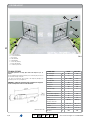
SYSTEM LAYOUT
Measurements in mm
A - XTILUS gearmotor
B - Control unit with box
C - Key selector
D - Tuned antenna
E - Flashing lamp
F - Photocells (external)
G - Photocells (internal)
H - Column for photocells
TECHNICAL FEATURES
Irreversible gearmotors for wing gates with a leaf length of up to 3,5
metres.
The irreversibility of this gearmotor allows you to avoid using any electric lock
for an effective closing of the gate.
The motor is protected by an heat probe, that temporary interrupts the
operating cycle in case of prolonged use.
WARNING: to optimize the functioning of the automation, we suggest to
use the slowing down at the end of the movement.
FIG. 1
TECHNICAL DATA XTILUS XTILUS 24V
Max. leaf weight Kg 400 350
Max. leaf lenght m 3,5 3,5
Power supply 230V - 50/60Hz 24Vdc
Current absorbed A 1 2,5
Motor power W 200 60
Towing speed m/s 0,10 Variable
Stem stroke mm 400 400
Gearmotor weight Kg 8,5 8,5
Capacitor µF 8 -
Daily operations suggested n° 150 200
Max consecutive operations n° 20 45
Service % 50 80
Unlocking device for
emergency manoeuvre
With key With key
Working temperature °C -20 ÷ +55 -20 ÷ +55
Protection IP 44 44
Average opening time s 20 14 ÷ 22
Max thrust N 1600 1600
A
A
B
C
D
E
F
F
H
H
G
G

ITA ENG FRA ESP DEU POR
9/20
ENG
www.remotecontrolgates.co.uk 01482 860950
XTILUS INSTALLATION
CHECKING BEFORE THE INSTALLATION
- THE GATE SHALL MOVE FRICTIONLESS -
Note: gate features must be uniformed with the standards and laws in force.
The door/gate can be automated only if it is in a good condition and its
conditions comply with the EN 12604 norm.
- The door/gate leaf does not have to have a pedestrian opening. In the
opposite case it is necessary to take the appropriate steps, in accordance
with EN 12453 norm, point 5.4.1 (for instance; by preventing the operation
of the motor when the pedestrian opening is opened, by installing a safety
microswitch connected with the control panel).
- Must not generate points of entrapment (e.g. between the leaf of the opened
gate and the fence).
- No mechanical stop shall be on top of the gate, since mechanical stops are
not safe enough.
Note: the leaf must be fixed firmily on the hinges to the pillars, must not be
flexible during the movement and must move without frictions.
Before the installation of motor, verify all dimensions etc.
RELEASE
To move the gate manually it is necessary to release the gearmotor
inserting the special key, turning it for 90° and lift up the lever (Fig. 2).
In order to carry out the manual operation of the gate leaf the followings must
be checked:
- That the gate is endowed with appropriate handles;
- That these appropriate handles are placed so to avoid safety risks for the
gearmotor;
- That the physical effort necessary to move the gate leaf should not be higher
than 225 N, for doors/gates for private dwellings, and, 390N for doors/gates
for commercial and industrial sites ( values indicated in 5.3.5 of the EN 12453
norm).
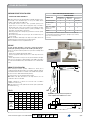
MODALITY OF INSTALLATION
Before fastening the brackets provided, establish the A and B (Fig. 3)
coordinates using the data given in Table 1. These data are valid if the gearmotor
is at maximum extension minus one centimetre of the available stroke (CD) when
the gate is closed to obtain maximum working efficiency.
To anchor the piston, use the fastening brackets provided.
Note: data B in the table, with reference to the single values A, are to be
considered as values recommended.
Establish coordinates A + B that are to be used: the sum of coordinates
establishes the stroke used C
U
.
Note: the stroke used (C
U
) of the gearmotor must never be equal or greater than
the available stroke (C
D
).
Parts to install meeting the EN 12453 standard
COMMAND TYPE
USE OF THE SHUTTER
Skilled persons
(out of public area*)
Skilled persons
(public area)
Unrestricted use
with manned operation A B not possible
with visible impulses
(e.g. sensor)
E E E
with not visible
impulses (e.g. remote
control device)
E E E
automatic E E E
* a typical example are those shutters which do not have access to any public way
A: Command button with manned operation (that is, operating as long as activated).
B: Key selector with manned operation.
E: Photocells.
FIG. 2
LOCKED
UNLOCKED
Metal key - optional
FIG. 3
TABLE 1
ANGLE A B C D E L Cu
110°
130 130 120 10 76 760 260
140 140 120 20 76 760 280
150 150 120 30 76 760 300
90°
(without
limit
switch)
160 160 120 40 76 760 320
175 175 120 55 76 760 350
160 190 120
70
76
760
350
150 200 120
80
76
760
350
A+B=C
U
(used stroke) C
D
= (max available stroke)=400 mm
A
B
E
C D
L
YES!
YES!
NO!
NO!
ATTENTION: in opening position, the angle should
not be negative. The installation is not correct.

ITA ENG FRA ESP DEU POR
10/20
ENG
www.remotecontrolgates.co.uk 01482 860950
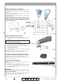
FIXING OF THE REAR PLATE TO THE COLUMN
Fix the rear plate to the column (Fig. 4) in accordance to the desired coordinates.
In case an iron pillar is available, screw directly onto the column the plate with
3 screws M8..
In case you need to fix the bracket onto a concrete pillar, use the fixing plate to
be fastened with 3 Fischer screws of Ø 8 mm.
When the backing plate is fixed, anchor the rear part of the piston to the plate
and fasten it firmly (Fig. 6).
ATTENTION: when establishing the height off the ground at which to fasten
the plate to the pillar (Fig. 4), keep in mind that the plate for anchoring
the piston to the gate must be fastened 40 mm below that on the post to
obtain horizontal levelling (Fig. 5).
FIXING OF THE FRONT PLATE TO THE GATE
For the fixing of the front plate to the leaf, follow this procedure:
1. Fit the anchor plate onto the piston. Insert the washer, tighten the bolt
firmly (Fig. 7).
ATTENTION: lubricate the hole of the front plate and the towing of the
motor with silicone grease before the fixing.
2. Close the gate.
3. Move the piston with the plate already fitted towards the gate.
4. Move the stem to the limit stop, then move it back by approximately 1 cm
and mark the position of the plate.
5. Realize the same operation in opening.
6. If positions correspond, fix the plate on the gate; otherwise revise A and B
coordinates (TABLE 1).
N.B.: during the installation, try several times to open and to close the gate,
controlling that the gearmotor does not touch the moving gate
ADJUSTMENT OF MECHANICAL LIMIT SWITCH - OPTIONAL
The gearmotor may be provided with mechanical limit switches, optional, in
opening and/or closing, if the gate is not fitted with a floor stop (Fig. 8).
To adjust, slacken the screws on the limit switch and move it to the desired
position. Lock the screws (Fig. 9).
FINAL CHECK OF THE INSTALLATION
Before to proceed with the electrical cabling of the motor, check the correct
movement of the gate:
1. Unlock the motor and move manually the wing of the gate.
2. If the wing moves easily, the installation is correct. Otherwise lubricate the
hinges, the hole in the front plate and the towing of the gate. Check the
correct installation of the motor.
MAINTENANCE
To be carried out exclusively by skilled persons after the power supply to
the motor has been interrupted.
Lubricate the hinges, the hole of the front plate, the towing of the motor and
check the thrust force generated by the gearmotor on the gate once a year.
Lubricate the nut screw with silicone grease every two years.
FIG. 5
FIG. 4
FIG. 7
FIG. 8
FIG. 9
Front plate Rear plate
PIN
Motor
Seeger
Plate
FIG. 6
ATTENTIONE: use a level
for the positioning of the
plates.
TIGHTEN
FIRMLY

ITA ENG FRA ESP DEU POR
11/20
ENG
www.remotecontrolgates.co.uk 01482 860950
TROUBLESHOOTING
PROBLEM PROBABLE CAUSE SOLUTION
By giving a command with the remote control or
with the key selector, the gate doesn’t open or the
motor doesn’t start.
230 volt mains voltage absent. Check the main switch.
Emergency STOP present.
Check for any STOP selectors or commands.
If not used, check the jumper on the STOP input of
the control unit.
Fuse blown. Replace with one of same value.
Power cable of motor not connected or faulty.
Connect the cable to the appropriate terminal
board or replace it.
The photocell is not functioning or the beam is
interrupted.
Check the connection, remove any obstacle across
the beam.
By giving a command with the remote control,
the gate does not open, but it works with the key
selector.
The remote control has not been memorized or the
battery is flat.
Carry out the remote control learning procedure on
the control unit or replace the battery with a new
one.
The gate starts, but stops immediately
The torque of the motor is insufficient. Modify the value of the torque in the control unit.
The value of the obstacle sensitivity (if present) it is
not suitable for the installation.
Modify the value of the sensitivity in the control
unit, if possible.
One wing opens and the other closes The wire connection is not correct.
Carry out the learning of the stroke with the BIOS2
/ BIOS2 ECO control unit.
Invert the connection of the cable of the motor
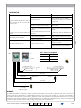
TYPICAL CONNECTION AND CABLE SECTION
GUARANTEE
In compliance with legislation, the manufacturer’s guarantee is valid from the date stamped on the product and is restricted to the repair or free replacement of the
parts accepted by the manufacturer as being defective due to poor quality materials or manufacturing defects. The guarantee does not cover damage or defects
caused by external agents, faulty maintenance, overloading, natural wear and tear, choice of incorrect product, assembly errors, or any other cause not imputable to
the manufacturer. Products that have been misused will not be guaranteed or repaired. Printed specifications are only indicative. The manufacturer does not accept any
responsibility for range reductions or malfunctions caused by environmental interference. The manufacturer’s responsibility for damage caused to persons resulting from
accidents of any nature caused by our defective products, are only those responsibilities that come under Italian law.
Control unit
230V: 4 x 1,5 mm
2
24V: 2 x 1,5 mm
2
230V: 4 x 1,5 mm
2
24V: 2 x 1,5 mm
2
2 x 0,75 mm
2
2 x 0,75 mm
2
TX photocell
RX photocell
4 x 0,75 mm
2
4 x 0,75 mm
2
3 x 1,5 mm
2
230V power supply
230V
24V
TABLE - CABLES FOR 230V MOTOR
Black Phase 1
Brown Phase 2
Grey or Light blue Common
Yellow green Ground

MADE IN ITALY
ALLMATIC S.r.l
32020 Lentiai - Belluno – Italy
Via dell’Artigiano, n°1 – Z.A.
Tel. 0437 751175 – 751163 r.a. Fax 0437 751065
www.remotecontrolgates.co.uk 01482 860950
6-1624846 rev.14 23/03/2016
-
 1
1
-
 2
2
-
 3
3
-
 4
4
-
 5
5
-
 6
6
-
 7
7


Allmatic XTILUS Manuale utente
- Categoria
- Gate Opener
- Tipo
- Manuale utente
- Questo manuale è adatto anche per
in altre lingue
- English: Allmatic XTILUS User manual