
PMA Prozeß- und Maschinen-Automation GmbH
rail line
Field bus coupler RL DP
Interface description
PROFIBUS-DP
9499-040-77111
valid from: 11/2005

© 2004-2005 PMA Prozeß- und Maschinen-Automation GmbH ·Printed in Germany
All rights reserved. No part of this document may be reproduced or published in any form
or by any means without prior written permission from the copyright owner.
A publication of PMA Prozeß- und Maschinen Automation
Postfach 310229
D-34058 Kassel
Germany
SIMATIC®is a registered trademark of Siemens AG
STEP®is a registered trademark of Siemens AG
is a registered trademark of the
PROFIBUS user organization (PNO)
BluePort ®and BlueControl ®are registered trademarks of
PMA Prozeß- und Maschinen-Automation GmbH
SyConÒis a registered trademark of
Hilscher Gesellschaft für Systemautomation GmbH
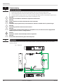
Legend of symbols:
gGeneral information
aGeneral warning
lCaution: ESD-hazarded components

Content
1. General ...........................................5
1.1 References........................................5
1.2 GSD file .........................................6
1.3 Additional information .................................6
2. Safety hints ..........................................7
2.1 Maintenance, modification and repair .........................8
2.2 Cleaning .........................................8
2.3 Spare parts .......................................8
3. Quick entry ..........................................9
4. Commissioning .......................................10
4.1 Hints for installation ..................................10
4.2 Dimensions.......................................10
4.3 Mounting ........................................11
4.3.1 Dismounting .................................11
4.4 Electrical connections .................................12
4.4.1 Bus coupler supply voltage .........................12
4.4.2 Energization via RL PWR power supply module...............12
4.4.3 Bus structure .................................13
4.4.4 Connector ..................................13
4.4.5 Cable layout .................................13
4.4.6 Screening...................................14
4.4.7 Terminating resistors ............................14
4.5 PROFIBUS settings ...................................15
4.5.1 Bus address .................................15
4.5.2 Communication parameters .........................15
4.6 Displays ........................................16
5. System design .......................................17
5.1 System structure ....................................17
5.1.1 Hints for connection .............................17
5.1.2 Operation without bus coupler .......................18
5.2 General system structure ...............................19
5.2.1 Minimum equipment of a PROFIBUS system ................19
5.2.2 Maximum equipment of a PROFIBUS system ................19
5.2.3 Wiring inside buildings ...........................20
6. Process data transmission ................................21
6.1 Selectable process data modules ...........................22
6.2 Predefined objects (A.x modules) ...........................22
6.2.1 Module A.1: Parameter channel ......................22
6.2.2 Module A.2: Data module : write order enabling ..............22
6.3 Freely selectable transfer object (analog modules) ..................23
6.3.1 Process data module “without data” ....................23
6.3.2 Process data modules in integer format...................23
6.3.3 Process data modules in floating point format ..............24
6.3.4 Example: specification of the number of process data ...........24

7. User parameter setting ....................................25
7.1 Parameter setting for DPV0 master ..........................25
7.1.1 System-wide parameter setting .......................25
7.1.2 Function module parameter setting .....................25
7.1.3 Fail-safe ...................................27
7.1.4 Example: module selection .........................28
7.2 Parameter setting for DPV1 master ..........................29
8. PROFIBUS DP diagnosis information ..........................30
8.1 Standard diagnosis message .............................30
8.2 Device-specific diagnosis .............................31
9. Engineering via PROFIBUS ................................32
9.1 BlueControl®via PROFIBUS-DPV1 ..........................32
9.1.1 CIF card settings ...............................33
9.1.2 BlueControl® settings ............................33
9.2 Hints for DP master set-up...............................34
10.Quick entry .........................................35
10.1 Example: SIMATIC®S7................................35
10.2 Example: make Hilscher interface card ........................38
10.2.1 Versions for DPV0 ..............................38
10.2.2 Versions for DPV1 ..............................41
11. Address areas and -formats ...............................42
11.1 Area definitions ....................................42
11.2 Special values .....................................42
11.3 Composition of the address tables ..........................43
11.4 Internal data types ...................................43
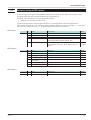
11.5 Annex of status / control information .........................44
11.5.1 Transmitter UNIFLEX CI 45..........................44
11.5.2 Universal controller KS 45 ..........................46
11.5.3 Temperature limiter TB 45 ..........................49
12.BlueControl
®
engineering tool ..............................50
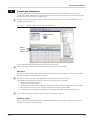
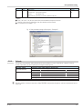
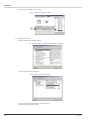
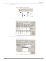
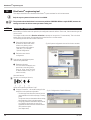
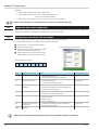
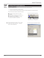
12.1 Defining the configuration ...............................50
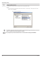
12.2 Comparison with actual configuration ........................52
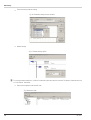
12.3 Viewing the process data on the bus coupler .....................52
12.4 Processing a function module engineering ......................53
12.4.1 Individual engineering ............................53
13.Index ...........................................54

1General
Thank you very much for buying a rail line series device. This document describes the PROFIBUS interface functions of
field bus coupler RL DP, which is called bus coupler in the following description, and the system capability of the
various module versions of the rail line series (CI45-1xx-2.., KS45-1xx-2..., TB45-1xx-2....), called “function module” in
the following description. The term “ device” applies to both bus coupler and function modules.
Bus couplers with a PROFIBUS interface permit the transmission of process, parameter and configuration data. Field
bus connection is via a sub-D socket at the top of the bus coupler. The serial communication interface facilitates
connections to supervisory systems, visualization tools, etc.
Another standard interface is the non-bussable ‘BluePort®’ front-panel (PC) interface. It is used for direct connection of
the ‘BlueControl®’ tool which runs on a PC.
Communication on the PROFIBUS-DP is according to the master/slave principle. The bus coupler is always slave.
The most important features of the bus connection with their physical and electrical properties are:
•Network topology
Linear bus, with bus termination at both ends.
•Transfer medium
screened, twisted 2-wire copper cable
•Cable length (without repeater)
Cable length dependent on transfer rate, max. 1200m
•Transfer rates
The following transfer rates are supported:
9,6 … 12000 kBit/s
•Physical interface
RS 485 via sub-D connector; connections can be made on site
•Addressing
1 ... 99
1.1 References
Additional information on the PROFIBUS protocol:
[1] PROFIBUS specifications
–http://www.profibus.com
Other documentations of rail line series s:
[3] Universal transmitter UNIFLEX CI 45
–Data sheet CI 45 9498 737 48313
–Operating note CI 45 9499 040 71441
–Operating manual CI 45 9499 040 71711
[4] Universal controller KS 45
–Data sheet KS 45 9498 737 48513
–Operating note KS 45 9499 040 71541
–Operating manual KS 45 9499 040 71811
[5] Temperature limiter TB 45
–Data sheet TB 45 9498 737 48413
–Operating note TB 45 9499 040 71641
–Operating manual TB 45 9499 040 71911
General
rail line References 5

1.2 GSD file
gThe GSD file is available as a standard file with English texts (PMA_093A.gsd). The current version can be downloaded
from item Software on our homepage www.pma-online.de .
1.3 Additional information
Information on bus coupler and function module parameter addresses is given in documentation 9499-040-78111.
General
6GSD file rail line

2Safety hints
This device was built and tested in compliance with VDE 0411-1 / EN 61010-1 and was shipped in safe condition.
The device meets European guideline 89/336/EEC (EMC) and is provided with the CE-marking.
The device was tested before delivery and has passed the tests stipulated in the test plan. To maintain this condition
and to ensure safe operation, the user must follow the hints and warnings given in this operating manual and operate
the device in compliance with the information provided in this manual.
aWarning
The device is provided exclusively for use as a measuring and control unit in technical systems.
aWarning
If the device is damaged to an extent that safe operation is not possible, it must not be taken into
operation.
ELECTRICAL CONNECTIONS
The electrical connections must conform to local standards (e.g. VDE 0100). The input leads must be kept separate
from signal and mains leads.
A circuit breaker or a power switch must be provided for the device and marked accordingly in the installation. The
circuit breaker or power switch must be installed near the device and should be easily accessible for the operator.
COMMISSIONING
Before device switch-on, ensure that the rules given below were followed:
wEnsure that the supply voltage corresponds to the specification on the type label.
wAll covers required for contact safety must be fitted.
wBefore device switch-on, check, if other equipment and/or facilities connected in the same signal loop is / are not
affected. If necessary, appropriate protective measures must be taken.
wThe device may be operated only when mounted in its enclosure.
wThe temperature limits specified for operation of the device must be met before and during operation.
aWarning
During operation, the ventilation slots of the housing must not be covered.
aWarning
The measurement inputs are designed for measurement of circuits which are not connected directly with
the mains supply (CAT I). The measurement inputs are designed for transient voltage peaks up to 800V
against PE.
SHUT-DOWN
For permanent shut-down, disconnect the instrument from all voltage sources and protect it against accidental
operation.
Before instrument switch-off, check that other equipment and / or facilities connected in the same signal loop is / are
not affected. If necessary, appropriate measures must be taken.
Safety hints
rail line 7

2.1 Maintenance, modification and repair
The devices need no particular maintenance.
No operable controls are mounted inside the device, i.e. the operator must not open it.
Modification, maintenance and repair may be carried out only by trained, authorized persons. For this purpose, the user
is invited to contact the PMA service.
aWarning
When opening the devices, or when removing covers and components, live parts or terminals can be
exposed.
lCaution
When opening the devices, electrostatically sensitive components can be exposed.
gThe PMA service address and contact information are as given below:
PMA Prozeß- und Maschinen-Automation GmbH
Miramstraße 87
D-34123 Kassel
Phone +49 (0)561 / 505-1257
Fax +49 (0)561 / 505-1357
e-mail: [email protected]
2.2 Cleaning
gHousing and front panel of the device can be cleansed using a dry, lint-free cloth.
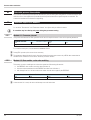
2.3 Spare parts
The following accessories are permitted as spare parts for the device:
Description Order no.
Connector set with screw terminals 9407-998-07101
Connector set with spring clamp terminals 9407-998-07111
Bus connector for fitting in top-hat rail 9407-998-07121
Safety hints
8Maintenance, modification and repair rail line

3Quick entry
For installing a rail line system, please, proceed as follows:
èDetermine system concept and function modules.
èDetermine the function module order behind the bus coupler.
èMount a bus connector for each module on the top-hat rail and push them together.
èSet the PROFIBUS address on the bottom of the bus coupler.
èTo mount the bus coupler, snap it onto the left bus connector.
èMount the function modules analogously in the planned order.
èConnect the bus coupler to the supply voltage.
èSet a unique address for each function module, which should start with 1 for the module next to the
bus coupler, followed by module no. 2, etc. Please, don’t leave an address gap.
Adjusting the addresses can be done via front-panel keyboard or BlueControl ®engineering tool.
èWrite the engineering for each individual function module. Determine which data should be read and /
or written via the field bus (menu Bus data (read) / Bus data (write)). Note the order of selected data.
èMake the function module wiring.
èConfigure the bus coupler with the order of fitted function modules. Please, specify the actually fitted
device types exactly.
This can be done via BlueControl®or via the master tool for the PROFIBUS master.
èDuring configuration in the master tool (via GSD file), the selected slot position determines the
required allocated function module address.
èLoad the bus configuration into the PROFIBUS master.
èConnect the PROFIBUS cable with the device; take care to include the required bus terminating
resistors.
èStart the data exchange with the PROFIBUS master !
Quick entry
rail line 9

4Commissioning
4.1 Hints for installation
wMeasurement and data lines should be kept separate from control and power supply cables.
wSensor measuring cables should be twisted and screened, with the screening connected to earth.
wExternal contactors, relays, motors, etc. must be fitted with RC snubber circuits to manufacturer specifications.
wThe unit must not be installed near strong electric and magnetic fields.
aWarning
The unit is not suitable for installation in explosion-hazarded areas.
aWarning
Faulty connection can lead to the destruction of the instrument.
aWarning
The device may be operated only in environments for which it is suitable due to its protection type.
aWarning
The housing ventilation slots must not be covered.
aWarning
In plants where transient voltage peaks are susceptible to occur, the devices must be equipped with
additional protective filters or voltage limiters!
lCaution!
The device contains electrostatically sensitive components .
aWarning
Please, follow the instructions given in the safety hints.
4.2 Dimensions
The bus coupler dimensions are shown in the following drawing. For the function module data, see the relevant
operating manuals.
Commissioning
10 Hints for installation rail line
117.5 (4,63”)
99 (3,90”)
22.5
111 (4,37”)
(0,87”)
2.3
(0,08”)
5.5
(0,20”)
21
22
23
24
Klemme /
terminal
PWR
4,0
(0,16”)
Fig. 1: Dimension

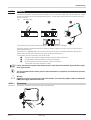
4.3 Mounting
Connection between bus coupler and function modules is via bus connectors, which snap onto the top-hat rail. Several
devices are mounted side by side with high packing density. The bus links between the devices are made directly via
the bus connectors.
The instruments are provided for vertical mounting on 35 mm top-hat rails to EN 50022.
If possible, the place of installation should be exempt of vibration, aggressive fluids (e.g. acid, lye), liquids, dust or
other suspended matters.
Instruments of the rail line family can be mounted directly side by side. For mounting and dismounting, the min.
distance above and below the instrument from other equipment should be 8 cm.
For installation of the bus connection, proceed as follows:
1Snap on the bus connectors (delivered with the device) onto the top-hat rail
2For high-density mounting, push the bus connectors together.
3Clip the instruments onto the top-hat rail via the bus connectors
- the internal system bus connection is ready!
+Please, mount the bus coupler in the leftmost position and fit the function modules right of the bus coupler
in the required order.
grail line instruments do not contain parts for which maintenance is compulsory and need not be opened by
the customer.
aWarning
A field bus coupler can energize max. 16 function modules. For connecting a higher number of modules RL
PWR power supply modules must be used.
4.3.1 Dismounting
Dismounting is in the inverse order of the steps described above.
Commissioning
rail line Mounting 11
1
top
1
top
2 3
Fig. 2 Mounting steps

4.4 Electrical connections
4.4.1 Bus coupler supply voltage
A system comprising bus coupler and one or several function modules is energized centrally via the bus coupler.
Central energization reduces the wiring expenditure considerably.
aWarning
Energization at the function modules is not permissible.
gA bus coupler can energize max. 16 function modules. For extension possibilities, see chapter 4.4.2.
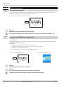
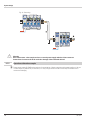
4.4.2 Energization via RL PWR power supply module
Power supply module RL PWR is used for energization of function modules with system interface via the bus connector
in the top-hat rail.
For connecting a higher number of function modules to the bus coupler than permissible for energization, additional
power supply modules must be used.
Applications:
•Supplementary energization of additional function modules
•Repartition to different installation levels (e.g. two rows in a control cabinet)
•Construction of separate potential levels
•A power supply module can energize up to 16 function modules.
aWarning
Energ. at the function modules is not permitted.
aWarning
High-density mounting with other partial systems is not permissible.
gCascade connection of power supply modules is not permissible (see above).
Commissioning
12 Electrical connections rail line
22
21 23 24
PWR
++
=24V
Fig. 3: Bus coupler energy supply conn. buscoupler
22
21 23 24
PWR
++
=24V
Fig. 4: Energy supply connection Fig. 5: Ex: power supply module

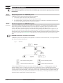
4.4.3 Bus structure
The bus is a two-wire RS 485 cable.
All bus sharing RS 485 units are connected in parallel to signals RxD/TxD-N (Data A) and RxD/TxD-P (Data B).
The bus cable characteristics are specified in IEC 61158. Cable type A is suitable for transfer rates up to 12 Mbit/s. A
twisted and screened 2-wire cable must be used.
gHints:
1Mount terminating resistors across Data A and B at the cable end. For procedure, see chapter 4.4.7.
2For screening, see chapter 4.4.6.
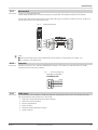
4.4.4 Connector
Field bus connection is via a “standard” PROFIBUS-DP connector. The connector is a sub-D socket to IEC 61158.
Connection must be done by the customer.
4.4.5 Cable layout
For connecting the field instruments, suitable bus cables for the application must be used. The wiring must comply
with the general hints and regulations (e.g. VDE 0100):
•Cable layout in buildings (inside and outside cabinets)
•Cable layout outside buildings
•Potential compensation
•Cable screening
•Measures against interference voltages
•Length of tap line
Commissioning
rail line Electrical connections 13
Fig. 6 Cabling possibilities
1
2
3
4
5
6
7
8
9
DGND
VP
RxD/TxD-P (B)
RxD/TxD-N (A)
Anschluss / connection:
PROFIBUS-DP
Fig. 7 Bus connecting plug

In particular, the following information must be taken into account:
•With RS 485 technology, max. 32 field units can be connected in a segment at a bus cable. Several segments
can be coupled by means of repeaters.
•The bus topology should be a line of max. 1000m length per segment. Extension by means of repeaters is
permissible.
•The bus cable connection must be a “daisy chain” between field instruments rather than star-shaped .
•If possible, tap lines should be avoided to prevent reflections causing communication trouble. With higher
transfer rates, tap lines are not permissible.
•The general hints for low-interference signal and bus cable wiring are applicable (see operating note „EMC –
General information“ (9407-047-09118)).
•To increase the transfer safety, pairwisely twisted and screened bus cables can be used.
4.4.6 Screening
The type of screening connection is dependent mainly on the expected interference.
•For suppression of electric fields, one end of the screening must be connected to earth. Always realize this
measure at first.
•However, suppression of interference due to an alternating magnetic field is possible only, when the both ends
of the screening are connected to earth. With earth circuits, however, note the screening effect is reduced by
galvanic interference on the reference potential.
•If several devices are linked to a single bus, the screen must be connected at each device, e.g. by means of
screen clamps.
•Short distance bus screening must have a large-surface, low-resistance connection to a central protective earth,
e.g. via screening terminals
4.4.7 Terminating resistors
The PROFIBUS terminating resistors must be fitted at the end of each bus cable, construction acc. to IEC 61158.
We recommend using commercially available PROFIBUS connectors with integrated terminating resistors.
Commissioning
14 Electrical connections rail line

4.5 PROFIBUS settings
4.5.1 Bus address
The address of a bus coupler for bus communication must be adjusted via two rotary selector switches at the bottom
of the unit:
Range:
•01 … 99
gEach instrument in a PROFIBUS system must have a unique address.
aWarning
When defining the device address, note that allocation of the same address to two instruments is not
permissible, because it is susceptible of causing faulty behaviour of the overall bus. In this case, the bus
master communication with the connected instruments is not possible.
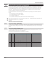
4.5.2 Communication parameters
Transfer rate / cable length
The Baudrate is a measure for the transfer rate. The permissible cable length is dependent on this rate.
The bus coupler supports the following transfer rates:
Transfer rate Max. cable length
9,6 / 19,2 / 45,45 / 93,75 kBit/s 1200 m
187,5 kBit/s 1000 m
500 kBit/s 400 m
1,5 MBit/s 200 m
3 / 6 / 12 MBit/s 100 m
The transfer rate is selected automatically by the bus master.
gThe transfer rate setting of all bus sharing units must be equal.
Process data length
The max. length of a process data message can be 244 bytes (read and write).
Commissioning
rail line PROFIBUS settings 15
x1
x10
Fig. 8 Address setting (below)

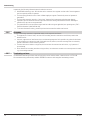
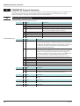
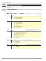
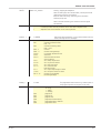
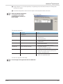
4.6 Displays
Five bus coupler indicator LEDs indicate various operating statuses.
* “ green- yellow- red-
off” alternating display: internal error status
Commissioning
16 Displays rail line
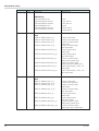
Signification
1
System bus status indicator LED
off: off
blinks: searching modules
on: communication active
2Diagnostic indicator LED
on: module error, alarm
3
Device status indicator LED *
green: ok
yellow: initialization
yellow blinking: configuration difference
red: no configuration
red blinking: module failure
4no function
5
Field bus status indicator LED
off: no communication
blinks: Wait / Param / Config / CPU Stop
on: data exchange
6
Field bus telegram error LED
off: no error
blinks: parameter error
on: configuration error
7PC connection for engineering tool

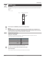
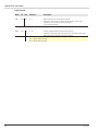
5System design
Up to 16 function modules can be connected and energized at a bus coupler. System extension is possible by using
power supply modules:
•Up to 62 function modules can be addressed logically by a bus coupler.
•Up to 4 installation levels can be built up.
•The max. permissible extension is 10 m.
5.1 System structure
Using power supply modules offers many advantages:
•The number of function modules connectable to a bus coupler can be extended.
•The function modules can be distributed to different levels in the control cabinet.
•A potential-isolated energy supply is possible.
gThe overall system length including cables must not exceed 10 m. Max. 3 m cable length between two
groups is permissible.
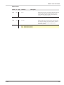
5.1.1 Hints for connection
For connecting the function modules energized by the bus coupler and the function modules energized by the power
supply module, proceed as follows:
1Insert a connector (e.g. 9407-998-07141) on the right side of the group with the bus coupler into the bus connector
in the top-hat rail.
2Insert a connector (e.g. 9407-998-07131) on the left side of the group with the power supply module into the bus
connector.
3Use twisted and screened two-wire bus cable.
Connect conductor 1 with the lower contact S5 and conductor 2 with contact S4.
4Terminate the system bus with a terminating resistor LT = 100.
For this, insert a connector (e.g. 9407-998-07141) on the right side of the last group with a power supply module
into the bus connector. Connect the resistor across terminals S4 - S5.
System design
rail line System structure 17
Versorgung / Power supply
interner Systembus / internal system bus
Fig. 9: System structure possibility

aWarning
Don’t interconnect a bus coupler and one or several power supply modules via bus connector.
Connections via contacts S1 to S3 can lead to damage of the connected devices!
5.1.2 Operation without bus coupler
gPower supply module RL PWR can be used also for energization of function modules with system interface, if the use
of a bus coupler is planned only for the future, or if only a single function module version may be available due to
reduced stock-keeping.
System design
18 System structure rail line
Fig. 10: Connecting

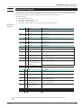
5.2 General system structure
gPlease, follow the guidelines and instructions for building up a communication system given by the master
manufacturer.
5.2.1 Minimum equipment of a PROFIBUS system
A PROFIBUS system comprises the following minimum equipment:
•a bus master, which controls the data communication,
•one or several slaves, which provide data on request by the master,
•the transfer medium, consisting of bus cable and bus connector for connecting the individual bus sharing units,
one or several bus segments which are connected by repeaters.
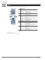
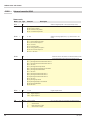
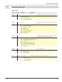
5.2.2 Maximum equipment of a PROFIBUS system
A bus segment comprises max. 32 (active and passive) field instruments. The maximum possible number of slaves
which can be operated at a PROFIBUS master over several segments is determined by the internal master memory
structure. Therefore you should get information on the master capacity when planning a system.
The bus cable can be opened at any point to include another unit by adding a bus connector. At the segment end, the
bus cable can be extended up to the predefined segments lengths. The length of a bus segment is dependent on the
adjusted transfer rate, which is determined mainly by system constellation (segment length, distributed inputs/outputs)
and required scanning cycles Abfragezyklen of individual units. The selected transfer rate must be equal for all bus
units.
+PROFIBUS units must be connected in line structure.
A PROFIBUS system can be extended by using repeaters for connection of more than 32 units, or for longer distances
than defined according to transfer rate.
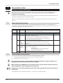
A fully equipped PROFIBUS system can include max. 125 units with addresses 1 ... 125. Each repeater reduces the
maximum number of units in a segment. As a passive unit, a repeater dos not have a PROFIBUS device address.
However, its input circuitry is an additional load for the segment due to bus driver current consumption. But a repeater
is without effect on the overall number of units connected on the bus. The maximum number of repeaters which can
be connected in series may vary dependent on manufacturer. For this reason, you should get information on possible
limitations from the manufacturer when projecting a system.
rail line General system structure 19
Slave without terminating resistor
Repeater without terminating resistor Repeater with terminating resistor
Slave with terminating resistor
Fig. 11 Structure

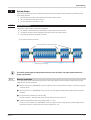
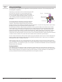
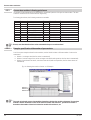
5.2.3 Wiring inside buildings
The following hints for cable layout are applicable to twisted-pair cables with screen. The screening improves the
electromagnetic compatibility.
Depending on requirements, the one or both ends of the cable
screen must be connected to a central earth point (PE) by
means of low-impedance connections with a large surface,
e.g. screen clamps. When installing a repeater or field unit in a
control cabinet, the cable screen should be connected to an
earth rail mounted as close as possible to the cable entry into
the cabinet.
The screening must be continued up to the field instrument
and connected with the conductant housing and/or metal
connector. Ensure that the earth potential of the instrument
housing and of the control cabinet accommodating the field instrument is is equal due to large-surface metal contact .
Mounting a screening rail on a painted surface is without effect.
By observing these measures, high-frequency interference will be grounded reliably via the cable screens. Should
external interference voltages still reach the data lines, the voltage potential will be raised symmetrically on both
lines, so that in general, no destructive voltage differences can arise. Normally, a shift of the ground potential by
several volts will not have an effect on reliable data transmission. If higher voltages are to be expected, a potential
balancing conductor with a minimum cross-section of 10 mm2should be installed parallel to the bus cable, with
connections to the reference ground of every field unit. In case of extreme interference, the bus cable can be installed
in a metal conduit or channel. The conduit tube or the channel must be earthed at regular distances.
The min. distance between bus cable and other leads carrying more than 60 V must be 20 cm. The bus cable must be
kept also separate from telephone cables and cables leading into hazardous areas. In these cases, we recommend
installing the bus cable in a separate cable duct.
When installing a cable duct, only conductant materials connected regularly with the reference potential should be
used . Mechanical stress and obvious damage must of the bus cables must be avoided. Unless this is possible, special
protective measures, e.g. installation in a pipe, etc. are required. such asIf thisDie Buskabel sind keiner mechanischen
Beanspruchung oder offensichtli
Floating installation
If the installation must be floating (no earth connection) for certain reasons, the device reference ground must only
have a high-impedance connection to earth (e.g. an RC combination). The system will then find its own earth potential.
When connecting repeaters for the purpose of linking two bus segments, a floating installation is recommended, to
prevent possible potential differences being transferred from one segment to the next.
20 General system structure rail line
Functional ground Cable screen
Earth rail in cabinet
near cable entry
Fig. 12 Screening conn.
La pagina si sta caricando...
La pagina si sta caricando...
La pagina si sta caricando...
La pagina si sta caricando...
La pagina si sta caricando...
La pagina si sta caricando...
La pagina si sta caricando...
La pagina si sta caricando...
La pagina si sta caricando...
La pagina si sta caricando...
La pagina si sta caricando...
La pagina si sta caricando...
La pagina si sta caricando...
La pagina si sta caricando...
La pagina si sta caricando...
La pagina si sta caricando...
La pagina si sta caricando...
La pagina si sta caricando...
La pagina si sta caricando...
La pagina si sta caricando...
La pagina si sta caricando...
La pagina si sta caricando...
La pagina si sta caricando...
La pagina si sta caricando...
La pagina si sta caricando...
La pagina si sta caricando...
La pagina si sta caricando...
La pagina si sta caricando...
La pagina si sta caricando...
La pagina si sta caricando...
La pagina si sta caricando...
La pagina si sta caricando...
La pagina si sta caricando...
La pagina si sta caricando...
La pagina si sta caricando...
La pagina si sta caricando...
-
 1
1
-
 2
2
-
 3
3
-
 4
4
-
 5
5
-
 6
6
-
 7
7
-
 8
8
-
 9
9
-
 10
10
-
 11
11
-
 12
12
-
 13
13
-
 14
14
-
 15
15
-
 16
16
-
 17
17
-
 18
18
-
 19
19
-
 20
20
-
 21
21
-
 22
22
-
 23
23
-
 24
24
-
 25
25
-
 26
26
-
 27
27
-
 28
28
-
 29
29
-
 30
30
-
 31
31
-
 32
32
-
 33
33
-
 34
34
-
 35
35
-
 36
36
-
 37
37
-
 38
38
-
 39
39
-
 40
40
-
 41
41
-
 42
42
-
 43
43
-
 44
44
-
 45
45
-
 46
46
-
 47
47
-
 48
48
-
 49
49
-
 50
50
-
 51
51
-
 52
52
-
 53
53
-
 54
54
-
 55
55
-
 56
56


West Control Solutions Rail line Profibus Manuale utente
- Tipo
- Manuale utente
- Questo manuale è adatto anche per
in altre lingue
Documenti correlati


Altri documenti
-
VIPA CPU 017-CEFPR00 Manuale del proprietario
-
-
-
-
YASKAWA VIPA System SLIO Manuale utente
-
-
AVENTICS Bus Coupler AES/Valve Driver AV Profibus DP Manuale utente
-
-
SICK WI180C-PB Profibus-Koppler Quickstart