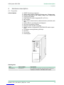
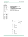
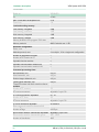
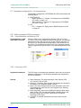
VIPA System 300S Manuale utente

Tipo
Manuale utente
CPU | 315-2AG13 | Manual
HB140 | CPU | 315-2AG13 | GB | Rev. 14-40
VIPA System 300S CPU
315-2AG13_000_CPU 315SB/DPM,1,GB - © 2014
VIPA GmbH
Ohmstr. 4
91074 Herzogenaurach
Telephone: +49 9132 744-0
Fax: +49 9132 744-1864
Internet: www.vipa.com
Table of contents
1 General...................................................................................... 6
1.1 Copyright © VIPA GmbH ................................................... 6
1.2 About this manual.............................................................. 7
1.3 Safety information.............................................................. 8
2 Basics..................................................................................... 10
2.1 Safety information for users............................................. 10
2.2 Operating structure of a CPU........................................... 10
2.2.1 General......................................................................... 10
2.2.2 Applications .................................................................. 11
2.2.3 Operands...................................................................... 11
2.3 CPU 315-2AG13.............................................................. 12
2.4 General data.................................................................... 14
3 Assembly and installation guidelines.................................. 17
3.1 Installation dimensions..................................................... 17
3.2 Assembly standard bus.................................................... 18
3.3 Cabling............................................................................. 19
3.4 Installation guidelines....................................................... 22
4 Hardware description............................................................ 25
4.1 Properties......................................................................... 25
4.2 Structure........................................................................... 26
4.2.1 General......................................................................... 26
4.2.2 Interfaces...................................................................... 26
4.2.3 Memory management................................................... 28
4.2.4 Storage media slot ....................................................... 28
4.2.5 Battery backup for clock and RAM................................ 28
4.2.6 Operating mode switch................................................. 29
4.2.7 LEDs............................................................................. 29
4.3 Technical data.................................................................. 31
5 Deployment CPU 315-2AG13................................................ 38
5.1 Assembly.......................................................................... 38
5.2 Start-up behavior.............................................................. 38
5.3 Addressing....................................................................... 39
5.3.1 Overview....................................................................... 39
5.3.2 Addressing Backplane bus I/O devices......................... 39
5.4 Hardware configuration - CPU......................................... 40
5.5 Hardware configuration - I/O modules............................. 41
5.6 Hardware configuration - Ethernet PG/OP channel......... 42
5.7 Hardware configuration - Communication........................ 44
5.8 Setting standard CPU parameters................................... 44
5.8.1 Parametrization via Siemens CPU................................ 44
5.8.2 Parameters CPU........................................................... 44
5.8.3 Parameters for DP........................................................ 47
5.8.4 Parameters for MPI/DP ................................................ 47
5.9 Setting VIPA specific CPU parameters............................ 48
5.9.1 Proceeding.................................................................... 48
5.9.2 VIPA specific parameters.............................................. 50
5.10 Project transfer............................................................... 53
VIPA System 300S CPU Table of contents
HB140 | CPU | 315-2AG13 | GB | Rev. 14-40 3
5.10.1 Transfer via MPI/PROFIBUS...................................... 53
5.10.2 Transfer via Ethernet................................................... 55
5.10.3 Transfer via MMC........................................................ 56
5.11 Access to the internal Web page................................... 57
5.12 Operating modes............................................................ 59
5.12.1 Overview..................................................................... 59
5.12.2 Function security......................................................... 61
5.13 Overall reset................................................................... 61
5.14 Firmware update............................................................ 63
5.15 Reset to factory setting.................................................. 65
5.16 Slot for storage media.................................................... 66
5.17 Memory extension with MCC......................................... 67
5.18 Extended know-how protection...................................... 68
5.19 MMC-Cmd - Auto commands......................................... 69
5.20 VIPA specific diagnostic entries..................................... 71
5.21 Control and monitoring of variables with test functions.. 87
6 Deployment PtP communication.......................................... 89
6.1 Fast introduction............................................................... 89
6.2 Principle of the data transfer............................................ 90
6.3 Deployment of RS485 interface for PtP .......................... 90
6.4 Parametrization................................................................ 93
6.4.1 FC/SFC 216 - SER_CFG.............................................. 93
6.5 Communication................................................................ 96
6.5.1 Overview....................................................................... 96
6.5.2 FC/SFC 217 - SER_SND.............................................. 97
6.5.3 FC/SFC 218 - SER_RCV............................................ 102
6.6 Protocols and procedures ............................................. 104
6.7 Modbus - Function codes .............................................. 108
6.8 Modbus - Example communication................................ 113
7 Deployment PROFIBUS communication........................... 116
7.1 Overview........................................................................ 116
7.2 Fast introduction............................................................. 116
7.3 Hardware configuration - CPU....................................... 117
7.4 Deployment as PROFIBUS DP master.......................... 118
7.5 Deployment as PROFIBUS DP slave............................ 119
7.6 PROFIBUS installation guidelines.................................. 121
7.7 Commissioning and Start-up behavior........................... 124
8 WinPLC7............................................................................... 126
8.1 System conception......................................................... 126
8.2 Installation...................................................................... 126
8.3 Example project engineering.......................................... 128
8.3.1 Job definition............................................................... 128
8.3.2 Project engineering..................................................... 128
8.3.3 Test the PLC program in the Simulator....................... 134
8.3.4 Transfer PLC program to CPU and its execution........ 135
9 Configuration with TIA Portal............................................. 137
9.1 TIA Portal - Work environment ...................................... 137
9.1.1 General....................................................................... 137
9.1.2 Work environment of the TIA Portal............................ 137
VIPA System 300S CPUTable of contents
HB140 | CPU | 315-2AG13 | GB | Rev. 14-40 4
9.2 TIA Portal - Hardware configuration - CPU ................... 138
9.3 TIA Portal - Hardware configuration - I/O modules........ 139
9.4 TIA Portal - Hardware configuration - Ethernet PG/OP
channel........................................................................... 140
9.5 TIA Portal - Setting VIPA specific CPU parameters....... 143
9.6 TIA Portal - Include VIPA library.................................... 145
9.7 TIA Portal - Project transfer............................................ 146
VIPA System 300S CPU Table of contents
HB140 | CPU | 315-2AG13 | GB | Rev. 14-40 5
1 General
1.1 Copyright © VIPA GmbH
This document contains proprietary information of VIPA and is not to
be disclosed or used except in accordance with applicable agree-
ments.
This material is protected by the copyright laws. It may not be repro-
duced, distributed, or altered in any fashion by any entity (either
internal or external to VIPA), except in accordance with applicable
agreements, contracts or licensing, without the express written con-
sent of VIPA and the business management owner of the material.
For permission to reproduce or distribute, please contact: VIPA,
Gesellschaft für Visualisierung und Prozessautomatisierung mbH
Ohmstraße 4, D-91074 Herzogenaurach, Germany
Tel.: +49 9132 744 -0
Fax.: +49 9132 744-1864
http://www.vipa.com
Every effort has been made to ensure that the information
contained in this document was complete and accurate at
the time of publishing. Nevertheless, the authors retain the
right to modify the information.
This customer document describes all the hardware units
and functions known at the present time. Descriptions may
be included for units which are not present at the customer
site. The exact scope of delivery is described in the
respective purchase contract.
Hereby, VIPA GmbH declares that the products and systems are in
compliance with the essential requirements and other relevant provi-
sions. Conformity is indicated by the CE marking affixed to the
product.
For more information regarding CE marking and Declaration of Con-
formity (DoC), please contact your local VIPA customer service
organization.
All Rights Reserved
CE Conformity Declara-
tion
Conformity Information
VIPA System 300S CPUGeneral
Copyright © VIPA GmbH
HB140 | CPU | 315-2AG13 | GB | Rev. 14-40 6
VIPA, SLIO, System 100V, System 200V, System 300V, System
300S, System 400V, System 500S and Commander Compact are
registered trademarks of VIPA Gesellschaft für Visualisierung und
Prozessautomatisierung mbH.
SPEED7 is a registered trademark of profichip GmbH.
SIMATIC, STEP, SINEC, TIA Portal, S7-300 and S7-400 are regis-
tered trademarks of Siemens AG.
Microsoft and Windows are registered trademarks of Microsoft Inc.,
USA.
Portable Document Format (PDF) and Postscript are registered trade-
marks of Adobe Systems, Inc.
All other trademarks, logos and service or product marks specified
herein are owned by their respective companies.
Contact your local VIPA Customer Service Organization representa-
tive if you wish to report errors or questions regarding the contents of
this document. If you are unable to locate a customer service centre,
contact VIPA as follows:
VIPA GmbH, Ohmstraße 4, 91074 Herzogenaurach, Germany
Telefax: +49 9132 744-1204
Contact your local VIPA Customer Service Organization representa-
tive if you encounter problems with the product or have questions
regarding the product. If you are unable to locate a customer service
centre, contact VIPA as follows:
VIPA GmbH, Ohmstraße 4, 91074 Herzogenaurach, Germany
Tel.: +49 9132 744-1150 (Hotline)
1.2 About this manual
This manual describes the SPEED7 CPU 315-2AG13 of the CPU
from VIPA. It contains a description of the construction, project imple-
mentation and usage.
Product Order number as of state:
CPU-HW CPU-FW DPM-FW
315SB/DPM 315-2AG13 01 V3.6.0 V3.2.4
The manual is targeted at users who have a background in automa-
tion technology.
The manual consists of chapters. Every chapter provides a self-con-
tained description of a specific topic.
Trademarks
Information product
support
Technical support
Objective and contents
Target audience
Structure of the manual
VIPA System 300S CPU General
About this manual
HB140 | CPU | 315-2AG13 | GB | Rev. 14-40 7
The following guides are available in the manual:
nAn overall table of contents at the beginning of the manual
nReferences with page numbers
The manual is available in:
nprinted form, on paper
nin electronic form as PDF-file (Adobe Acrobat Reader)
Important passages in the text are highlighted by following icons and
headings:
DANGER!
Immediate or likely danger. Personal injury is possible.
CAUTION!
Damages to property is likely if these warnings are not
heeded.
Supplementary information and useful tips.
1.3 Safety information
The system is constructed and produced for:
ncommunication and process control
nindustrial applications
noperation within the environmental conditions specified in the
technical data
ninstallation into a cubicle
DANGER!
This device is not certified for applications in
in explosive environments (EX-zone)
The manual must be available to all personnel in the
nproject design department
ninstallation department
ncommissioning
noperation
Guide to the document
Availability
Icons Headings
Applications con-
forming with specifica-
tions
Documentation
VIPA System 300S CPUGeneral
Safety information
HB140 | CPU | 315-2AG13 | GB | Rev. 14-40 8
CAUTION!
The following conditions must be met before using or
commissioning the components described in this
manual:
Hardware modifications to the process control system
should only be carried out when the system has been
disconnected from power!
Installation and hardware modifications only by prop-
erly trained personnel.
The national rules and regulations of the respective
country must be satisfied (installation, safety, EMC ...)
National rules and regulations apply to the disposal of the unit!Disposal
VIPA System 300S CPU General
Safety information
HB140 | CPU | 315-2AG13 | GB | Rev. 14-40 9
2 Basics
2.1 Safety information for users
VIPA modules make use of highly integrated components in MOS-
Technology. These components are extremely sensitive to over-vol-
tages that can occur during electrostatic discharges. The following
symbol is attached to modules that can be destroyed by electrostatic
discharges.
The Symbol is located on the module, the module rack or on packing
material and it indicates the presence of electrostatic sensitive equip-
ment. It is possible that electrostatic sensitive equipment is destroyed
by energies and voltages that are far less than the human threshold
of perception. These voltages can occur where persons do not dis-
charge themselves before handling electrostatic sensitive modules
and they can damage components thereby, causing the module to
become inoperable or unusable. Modules that have been damaged
by electrostatic discharges can fail after a temperature change,
mechanical shock or changes in the electrical load. Only the conse-
quent implementation of protection devices and meticulous attention
to the applicable rules and regulations for handling the respective
equipment can prevent failures of electrostatic sensitive modules.
Modules must be shipped in the original packing material.
When you are conducting measurements on electrostatic sensitive
modules you should take the following precautions:
nFloating instruments must be discharged before use.
nInstruments must be grounded.
Modifying electrostatic sensitive modules you should only use sol-
dering irons with grounded tips.
CAUTION!
Personnel and instruments should be grounded when
working on electrostatic sensitive modules.
2.2 Operating structure of a CPU
2.2.1 General
The CPU contains a standard processor with internal program
memory. In combination with the integrated SPEED7 technology the
unit provides a powerful solution for process automation applications
within the System 300S family. A CPU supports the following modes
of operation:
ncyclic operation
ntimer processing
nalarm controlled operation
npriority based processing
Handling of electro-
static sensitive modules
Shipping of modules
Measurements and
alterations on electro-
static sensitive modules
VIPA System 300S CPUBasics
Operating structure of a CPU > General
HB140 | CPU | 315-2AG13 | GB | Rev. 14-40 10
Cyclicprocessing represents the major portion of all the processes
that are executed in the CPU. Identical sequences of operations are
repeated in a never-ending cycle.
Where a process requires control signals at constant intervals you
can initiate certain operations based upon a timer, e.g. not critical
monitoring functions at one-second intervals.
If a process signal requires a quick response you would allocate this
signal to an alarm controlled procedure. An alarm can activate a
procedure in your program.
The above processes are handled by the CPU in accordance with
their priority. Since a timer or an alarm event requires a quick reac-
tion, the CPU will interrupt the cyclic processing when these high-pri-
ority events occur to react to the event. Cyclic processing will resume,
once the reaction has been processed. This means that cyclic pro-
cessing has the lowest priority.
2.2.2 Applications
The program that is present in every CPU is divided as follows:
nSystem routine
nUser application
The system routine organizes all those functions and procedures of
the CPU that are not related to a specific control application.
This consists of all the functions that are required for the processing
of a specific control application. The operating modules provide the
interfaces to the system routines.
2.2.3 Operands
The following series of operands is available for programming the
CPU:
nProcess image and periphery
nBit memory
nTimers and counters
nData blocks
The user application can quickly access the process image of the
inputs and outputs PIO/PII. You may manipulate the following types
of data:
nindividual Bits
nBytes
nWords
nDouble words
Cyclic processing
Timer processing
Alarm controlled pro-
cessing
Priority based pro-
cessing
System routine
User application
Process image and
periphery
VIPA System 300S CPU Basics
Operating structure of a CPU > Operands
HB140 | CPU | 315-2AG13 | GB | Rev. 14-40 11
You may also gain direct access to peripheral modules via the bus
from user application. The following types of data are available:
nBytes
nWords
nBlocks
The bit memory is an area of memory that is accessible by means of
certain operations. Bit memory is intended to store frequently used
working data.
You may access the following types of data:
nindividual Bits
nBytes
nWords
nDouble words
In your program you may load cells of the timer with a value between
10ms and 9990s. As soon as the user application executes a start-
operation, the value of this timer is decremented by the interval that
you have specified until it reaches zero.
You may load counter cells with an initial value (max. 999) and incre-
ment or decrement these when required.
A data block contains constants or variables in the form of bytes,
words or double words. You may always access the current data
block by means of operands.
You may access the following types of data:
nindividual Bits
nBytes
nWords
nDouble words
2.3 CPU 315-2AG13
The CPU 315-2AG13 bases upon the SPEED7 technology. This sup-
ports the CPU at programming and communication by means of co-
processors that causes a power improvement for highest needs.
nThe CPU is programmed in STEPÒfrom Siemens. For this you
may use the SIMATIC Manager or TIA Portal from Siemens. Here
the instruction set of the S7-400 from Siemens is used.
nModules and CPUs of the System 300S from VIPA and Siemens
may be used at the bus as a mixed configuration.
nThe user application is stored in the battery buffered RAM or on
an additionally pluggable MMC storage module.
nThe CPU is configured as CPU 317-2DP (6ES7 317-2AJ10-0AB0/
V2.6) from Siemens.
Bit Memory
Timers and counters
Data Blocks
Overview
VIPA System 300S CPUBasics
CPU 315-2AG13
HB140 | CPU | 315-2AG13 | GB | Rev. 14-40 12
Please always use the CPU 317-2DP (6ES7
317-2AJ10-0AB0/V2.6) from Siemens of the hardware
catalog to project this CPU from VIPA. For the project
engineering, a thorough knowledge of the Siemens
SIMATIC Manager and the hardware configurator from
Siemens is required!
The CPU has an integrated memory. Information about the capacity
of the memory may be found at the front of the CPU. The memory is
divided into the following parts:
nLoad memory 2Mbyte
nCode memory (50% of the work memory)
nData memory (50% of the work memory)
nWork memory 1Mbyte
There is the possibility to extend the work memory to its max-
imum printed capacity 2Mbyte by means of a MCC memory
extension card.
Access
Memory
VIPA System 300S CPU Basics
CPU 315-2AG13
HB140 | CPU | 315-2AG13 | GB | Rev. 14-40 13
The CPU has a PROFIBUS/PtP interface with a fix pinout. After an
overall reset the interface is deactivated. By appropriate configura-
tion, the following functions for this interface may be enabled:
nPROFIBUS DP master operation: Configuration via PROFIBUS
sub module with ‘Operation mode’ Master in the hardware config-
uration.
nPROFIBUS DP slave operation: Configuration via PROFIBUS sub
module with ‘Operation mode’ Slave in the hardware configura-
tion.
nPtP functionality: Configuration as virtual PROFIBUS master
system by including the VIPA SPEEDBUS.GSD.
The CPU has an Ethernet interface for PG/OP communication. After
assigning IP address parameters with your configuration tool, via the
"PLC" functions you may directly access the Ethernet PG/OP channel
and program res. remote control your CPU. You may also access the
CPU with a visualization software via these connections.
nWiring by means of spring pressure connections (CageClamps) at
the front connector
nCore cross-section 0.08...2.5mm2
nTotal isolation of the wiring at module change
nPotential separation of all modules to the backplane bus
Dimensions of the basic enclosure:
n1tier width: (WxHxD) in mm: 40x125x120
The CPU comes with an integrated power supply. The power supply
is to be supplied with DC 24V. By means of the supply voltage, the
internal electronic is supplied as well as the connected modules via
backplane bus. The power supply is protected against inverse polarity
and overcurrent.
2.4 General data
Conformity and approval
Conformity
CE 2006/95/EG Low-voltage directive
2004/108/EG EMC directive
Approval
UL UL 508 Approval for USA and Canada
Integrated PROFIBUS
DP master/slave respec-
tively PtP functionality
Integrated Ethernet PG/
OP channel
Operation Security
Dimensions/ Weight
Integrated power supply
VIPA System 300S CPUBasics
General data
HB140 | CPU | 315-2AG13 | GB | Rev. 14-40 14
Conformity and approval
others
RoHS 2011/65/EU Product is lead-free; Restriction of the use of
certain hazardous substances in electrical and
electronic equipment
Protection of persons and device protection
Type of protection - IP20
Electrical isolation
to the field bus - electrically isolated
to the process level - electrically isolated
Insulation resistance -
Insulation voltage to reference earth
Inputs / outputs - AC / DC 50V, test voltage AC 500V
Protective measures - against short circuit
Environmental conditions to EN 61131-2
Climatic
Storage / transport EN 60068-2-14 -25…+70°C
Operation
Horizontal installation EN 61131-2 0…+60°C
Vertical installation EN 61131-2 0…+60°C
Air humidity EN 60068-2-30 RH1
(without condensation, rel. humidity 10…95%)
Pollution EN 61131-2 Degree of pollution 2
Mechanical
Oscillation EN 60068-2-6 1g, 9Hz ... 150Hz
Shock EN 60068-2-27 15g, 11ms
Mounting conditions
Mounting place - In the control cabinet
Mounting position - Horizontal and vertical
VIPA System 300S CPU Basics
General data
HB140 | CPU | 315-2AG13 | GB | Rev. 14-40 15
EMC Standard Comment
Emitted interfer-
ence
EN 61000-6-4 Class A (Industrial area)
Noise immunity
zone B
EN 61000-6-2 Industrial area
EN 61000-4-2 ESD
8kV at air discharge (degree of severity 3),
4kV at contact discharge (degree of severity
2)
EN 61000-4-3 HF field immunity (casing)
80MHz … 1000MHz, 10V/m, 80% AM (1kHz)
1.4GHz ... 2.0GHz, 3V/m, 80% AM (1kHz)
2GHz ... 2.7GHz, 1V/m, 80% AM (1kHz)
EN 61000-4-6 HF conducted
150kHz … 80MHz, 10V, 80% AM (1kHz)
EN 61000-4-4 Burst, degree of severity 3
EN 61000-4-5 Surge, installation class 3 *
*) Due to the high-energetic single pulses with Surge an appropriate external protective circuit with lightning protection elements like conductors
for lightning and overvoltage is necessary.
VIPA System 300S CPUBasics
General data
HB140 | CPU | 315-2AG13 | GB | Rev. 14-40 16
3 Assembly and installation guidelines
3.1 Installation dimensions
2tier width (WxHxD) in mm: 40 x 125 x 120Dimensions Basic
enclosure
Dimensions
Installation dimensions
VIPA System 300S CPU Assembly and installation guidelines
Installation dimensions
HB140 | CPU | 315-2AG13 | GB | Rev. 14-40 17
3.2 Assembly standard bus
The single modules are directly installed on a profile rail and con-
nected via the backplane bus connector. Before installing the mod-
ules you have to clip the backplane bus connector to the module from
the backside. The backplane bus connector is delivered together with
the peripheral modules.
Order number A B C
390-1AB60 160 140 10
390-1AE80 482 466 8.3
390-1AF30 530 500 15
390-1AJ30 830 800 15
390-9BC00* 2000 Drillings only left 15
*) Unit pack: 10 pieces
Measures in mm
For the communication between the modules the System 300S uses
a backplane bus connector. Backplane bus connectors are included
in the delivering of the peripheral modules and are clipped at the
module from the backside before installing it to the profile rail.
General
Profile rail
Bus connector
VIPA System 300S CPUAssembly and installation guidelines
Assembly standard bus
HB140 | CPU | 315-2AG13 | GB | Rev. 14-40 18
Please regard the allowed environment temperatures:
nhorizontal assembly: from 0 to 60°C
nvertical assembly: from 0 to 40°C
nlying assembly: from 0 to 40°C
1. Bolt the profile rail with the background (screw size: M6), so that
you still have minimum 65mm space above and 40mm below
the profile rail.
2. If the background is a grounded metal or device plate, please
look for a low-impedance connection between profile rail and
background.
3. Connect the profile rail with the protected earth conductor. For
this purpose there is a bolt with M6-thread.
4. The minimum cross-section of the cable to the protected earth
conductor has to be 10mm2.
5. Stick the power supply to the profile rail and pull it to the left side
to the grounding bolt of the profile rail.
6. Fix the power supply by screwing.
7. Take a backplane bus connector and click it at the CPU from the
backside like shown in the picture.
8. Stick the CPU to the profile rail right from the power supply and
pull it to the power supply.
9. Click the CPU downwards and bolt it like shown.
10. Repeat this procedure with the peripheral modules, by clicking a
backplane bus connector, stick the module right from the mod-
ules you've already fixed, click it downwards and connect it with
the backplane bus connector of the last module and bolt it.
3.3 Cabling
CAUTION!
The power supplies must be released before installa-
tion and repair tasks, i.e. before handling with the
power supply or with the cabling you must disconnect
current/voltage (pull plug, at fixed connection switch off
the concerning fuse)!
Installation and modifications only by properly trained
personnel!
Assembly possibilities
Approach
VIPA System 300S CPU Assembly and installation guidelines
Cabling
HB140 | CPU | 315-2AG13 | GB | Rev. 14-40 19
For the cabling of power supply of a CPU, a green plug with Cage-
Clamp technology is deployed. The connection clamp is realized as
plug that may be clipped off carefully if it is still cabled.
Here wires with a cross-section of 0.08mm2 to 2.5mm2 may be con-
nected. You can use flexible wires without end case as well as stiff
wires.
1 Test point for 2mm test tip
2 Locking (orange) for screwdriver
3 Round opening for wires
The picture on the left side shows the cabling step by step from top
view.
1. For cabling you push the locking vertical to the inside with a
suiting screwdriver and hold the screwdriver in this position.
2. Insert the de-isolated wire into the round opening. You may use
wires with a cross-section from 0.08mm2 to 2.5mm2
3. By removing the screwdriver the wire is connected safely with
the plug connector via a spring.
In the following the cabling of the two variants are shown.
CageClamp technology
(green)
Front connectors of the
in-/output modules
VIPA System 300S CPUAssembly and installation guidelines
Cabling
HB140 | CPU | 315-2AG13 | GB | Rev. 14-40 20
  • Page 1 1
  • Page 2 2
  • Page 3 3
  • Page 4 4
  • Page 5 5
  • Page 6 6
  • Page 7 7
  • Page 8 8
  • Page 9 9
  • Page 10 10
  • Page 11 11
  • Page 12 12
  • Page 13 13
  • Page 14 14
  • Page 15 15
  • Page 16 16
  • Page 17 17
  • Page 18 18
  • Page 19 19
  • Page 20 20
  • Page 21 21
  • Page 22 22
  • Page 23 23
  • Page 24 24
  • Page 25 25
  • Page 26 26
  • Page 27 27
  • Page 28 28
  • Page 29 29
  • Page 30 30
  • Page 31 31
  • Page 32 32
  • Page 33 33
  • Page 34 34
  • Page 35 35
  • Page 36 36
  • Page 37 37
  • Page 38 38
  • Page 39 39
  • Page 40 40
  • Page 41 41
  • Page 42 42
  • Page 43 43
  • Page 44 44
  • Page 45 45
  • Page 46 46
  • Page 47 47
  • Page 48 48
  • Page 49 49
  • Page 50 50
  • Page 51 51
  • Page 52 52
  • Page 53 53
  • Page 54 54
  • Page 55 55
  • Page 56 56
  • Page 57 57
  • Page 58 58
  • Page 59 59
  • Page 60 60
  • Page 61 61
  • Page 62 62
  • Page 63 63
  • Page 64 64
  • Page 65 65
  • Page 66 66
  • Page 67 67
  • Page 68 68
  • Page 69 69
  • Page 70 70
  • Page 71 71
  • Page 72 72
  • Page 73 73
  • Page 74 74
  • Page 75 75
  • Page 76 76
  • Page 77 77
  • Page 78 78
  • Page 79 79
  • Page 80 80
  • Page 81 81
  • Page 82 82
  • Page 83 83
  • Page 84 84
  • Page 85 85
  • Page 86 86
  • Page 87 87
  • Page 88 88
  • Page 89 89
  • Page 90 90
  • Page 91 91
  • Page 92 92
  • Page 93 93
  • Page 94 94
  • Page 95 95
  • Page 96 96
  • Page 97 97
  • Page 98 98
  • Page 99 99
  • Page 100 100
  • Page 101 101
  • Page 102 102
  • Page 103 103
  • Page 104 104
  • Page 105 105
  • Page 106 106
  • Page 107 107
  • Page 108 108
  • Page 109 109
  • Page 110 110
  • Page 111 111
  • Page 112 112
  • Page 113 113
  • Page 114 114
  • Page 115 115
  • Page 116 116
  • Page 117 117
  • Page 118 118
  • Page 119 119
  • Page 120 120
  • Page 121 121
  • Page 122 122
  • Page 123 123
  • Page 124 124
  • Page 125 125
  • Page 126 126
  • Page 127 127
  • Page 128 128
  • Page 129 129
  • Page 130 130
  • Page 131 131
  • Page 132 132
  • Page 133 133
  • Page 134 134
  • Page 135 135
  • Page 136 136
  • Page 137 137
  • Page 138 138
  • Page 139 139
  • Page 140 140
  • Page 141 141
  • Page 142 142
  • Page 143 143
  • Page 144 144
  • Page 145 145
  • Page 146 146
  • Page 147 147
  • Page 148 148

VIPA System 300S Manuale utente

Tipo
Manuale utente

in altre lingue