Immergas COD.3.023950 Istruzioni per l'uso
- Tipo
- Istruzioni per l'uso

IT IE
Cod. 1.035612 - Rev. ST.000317/002
IL PRESENTE FOGLIO È DA LASCIARE ALL'UTENTE
ABBINATO AL LIBRETTO ISTRUZIONI DELLA CALDAIA
THIS SHEET MUST BE LEFT WITH THE USER ALONG WITH
THE BOILER INSTRUCTION BOOKLET
Avvertenze generali.
Tutti i prodotti sono protetti con idoneo imballaggio da trasporto.
Il materiale deve essere immagazzinato in ambienti asciutti ed al
riparo dalle intemperie.
Il presente foglio istruzioni contiene informazioni tecniche relative
all’installazione del kit. Per quanto concerne le altre tematiche corre-
late all’installazione del kit stesso (a titolo esemplicativo: sicurezza
sui luoghi di lavoro, salvaguardia dell’ambiente, prevenzioni degli
infortuni), è necessario rispettare i dettami della normativa vigente
ed i principi della buona tecnica.
L’installazione o il montaggio improprio dell’apparecchio e/o dei
componenti, accessori, kit e dispositivi potrebbe dare luogo a proble-
matiche non prevedibili a priori nei confronti di persone, animali,
cose. Leggere attentamente le istruzioni a corredo del prodotto per
una corretta installazione dello stesso.
L’installazione e la manutenzione devono essere eettuate in ottem-
peranza alle normative vigenti, secondo le istruzioni del costruttore e
da parte di personale abilitato nonché professionalmente qualicato,
intendendo per tale quello avente specica competenza tecnica nel
settore degli impianti, come previsto dalla Legge.
General warnings.
All products are protected with suitable transport packaging.
e material must be stored in dry environments and protected
against weathering.
is instruction manual provides technical information for installing
the kit. As for the other issues related to kit installation (e.g. safety
in the work site, environment protection, injury prevention), it is
necessary to comply with the provisions specied in the regulations
in force and principles of good practice.
Improper installation or assembly of the appliance and/or compo-
nents, accessories, kit and devices can cause unexpected problems
to people, animals and objects. Read the instructions provided with
the product carefully to ensure a proper installation.
Installation and maintenance must be performed in compliance with
the regulations in force, according to the manufacturer's instructions
and by authorised professionally qualied sta, intending sta with
specic technical skills in the plant sector, as envisioned by the Law.
KIT VALVOLA TRE VIE PER ABBINAMENTO
UNITÀ BOLLITORE VICTRIX PRO
COD. 3.023950
3WAY VALVE KIT TO COUPLE THE BOILER
UNIT VICTRIX PRO
COD. 3.023950
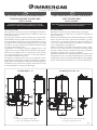
Fig. 1
VICTRIX PRO 35 - 55 VICTRIX PRO 80 - 100 - 120
Legenda:
1 - Kit sicurezze INAIL per caldaia singola
2 - Kit tre vie per abbinamento a Unità bollitore
Key:
1 - INAIL safety devices kit for individual boiler
2 - 3-way kit for coupling to boiler unit

11
1
G1"1/2
2
3
4
5
6
7
7
1
G1"
G1"1/2
G1"
7
MR
RU
MU
Montaggio Kit.
Premontare il gruppo tre vie in ottone (4) con il motorino (5),
in modo che il lato morsettiera dello stesso sia posizionato verso
il lato "B" stampato sul corpo tre vie in ottone (4), accessibile
comunque dalla parte anteriore della caldaia.
Montare il tubo (6) alla valvola miscelatrice (lato A) interponendo
la relativa guarnizione (7) senza serrare a fondo il dado.
Montare la valvola (4) con tubo (6) al collettore (3) interponendo
le relative guarnizioni (7) senza serrare a fondo i dadi.
Al termine serrare a fondo tutti i dadi di collegamento.
Collegare il kit 3 vie per abbinamento unità bollitore come da
gura 2 assicurandosi di interporre le guarnizioni (1).
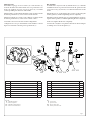
Fig. 2
Rif Descrizione componenti kit Qtà
1Guarnizione 44 x 34 x 2 4
2Tronchetto di ritorno da unità bollitore coibentato 1
3Tronchetto di mandata all'unità bollitore coibentato 1
4Valvola 3 vie in ottone 1
5Motore azionamento valvola 1
6Tubo di raccordo 1
7Guarnizione 30 x 22 x 2 4
Legenda:
M - Mandata impianto
R - Ritorno impianto
MU - Mandata a unità bollitore
RU - Ritorno da unità bollitore
Kit Assembly.
Assemble the 3-way brass unit (4) with the motor (5) so that the
terminal block side is positioned towards side "B" printed on the
3-way brass body (4), however, accessible from the front of the
boiler.
Mount the pipe (6) to the mixing valve (side A) by inserting the
relative gasket (7) without tightening the nut completely.
Mount the valve (4) with the pipe (6) to the manifold (3) by insert-
ing the relative gaskets (7) without tightening the nuts completely.
At the end, tighten all the nuts completely.
Connect the 3-way kit to couple the boiler unit as shown in gure
2, making sure to insert the gaskets (1).
Ref. Kit components description Qty
1Gasket 44 x 34 x 2 4
2Return section from the insulated boiler unit 1
3Flow section to the insulated boiler unit 1
43-way brass valve 1
5Valve driving motor 1
6Connection tube 1
7Gasket 30 x 22 x 2 4
Key:
M - System ow
R - System return
MU - Flow to boiler unit
RU - Return from boiler unit

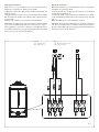
Fig. 3
Legenda:
B2 - Sonda sanitario
M30 - Valvola tre vie
Allacciamento elettrico.
N.B.: nel caso in cui il bollitore abbia una sonda premontata,
eliminarla e sostituirla con quella presente nel kit.
Collegare la sonda boiler (B2) presente nel kit sui morsetti R e H
della morsettiera.
Collegare i cavi nero, arancio e rosso provenienti dal motore (M30)
alla morsettiera di caldaia come indicato nello schema elettrico
sottoriportato.
N.B.: la sonda sanitario è riconosciuta automaticamente.
Attenzione: La caldaia ha un grado di isolamento elettrico IPX5D
e può essere installata anche all'esterno senza bisogno di prote-
zioni aggiuntive, è opportuno comunque se installati all'esterno
coibentare le tubazioni e proteggere dagli agenti atmosferici il kit
in base al suo grado di protezione elettrica.
Electrical connection:
N.B.: if the boiler has a pre-assembled probe, remove it and replace
it with the one present in the kit.
Connect the boiler probe (B2) present in the kit on terminals R
and H of the terminal block.
Connect the black, orange and red wires from the motor (M30)
to the terminal block of the boiler as shown in the wiring diagram
below.
N.B.: the DHW probe is automatically recognised.
Attention: e boiler has an IPX5D electric insulation rating and
can also be installed outdoors without additional protections.
However, if installed outdoors, the piping should be insulated and
the kit protected from the elements.
Key:
B2 - Domestic hot water probe
M30 - ree-way valve
Black
Black
Blue
Brown
Orange
Red

-
 1
1
-
 2
2
-
 3
3
-
 4
4