DTS XR2000 SPOT CMY Manuale utente
- Categoria
- Proiettori
- Tipo
- Manuale utente

GB
Made in Italy
XR2000 SPOT CMY
User’s Manual Rel 1.6
D.T.S. Illuminazione srl - ITALY
http://www.dts-lighting.it

Le informazioni contenute in questo documento sono state attentamente redatte e controllate. Tuttavia
non è assunta alcuna responsabilità per eventuali inesattezze. Tutti i diritti sono riservati e questo
documento non può essere copiato, fotocopiato, riprodotto per intero o in parte senza previo consenso
scritto della D.T.S .
DTS si riserva il diritto di apportare senza preavviso cambiamenti e modifiche estetiche , funzionali o di
design a ciascun proprio prodotto. D.T.S non assume alcuna responsabilità sull’uso o sull’applicazione dei
prodotti o dei circuiti descritti.
The information contained in this publication has been carefully prepared and checked. However, no
responsibility will be taken for any errors. All rights are reserved and this document cannot be copied,
photocopied or reproduced, in part or completely, without prior written consent from D.T.S.
D.T.S. reserves the right to make any aesthetic, functional or design modifications to any of its products
without prior notice. D.T.S. assumes no responsibility for the use or application of the products or circuits
described herein.
Les informations contenues dans le présent manuel ont été rédigées et contrôlées avec le plus grand
soin. Nous déclinons toutefois toute responsabilité en cas d'éventuelles inexactitudes. Tous droits
réservés. Ce document ne peut être copié, photocopié ou reproduit, dans sa totalité ou partiellement,
sans le consentement préalable de .
se réserve le droit d'apporter toutes modifications et améliorations esthétiques, fonctionnelles ou
de design, sans préavis, à chacun de ses produits. décline toute responsabilité sur l'utilisation ou
sur l'application des produits ou des circuits décrits.
D.T.S
D.T.S.
D.T.S.
Las informaciones contenidas en este documento han sido cuidadosamenteredactadas y
controladas. Con todo, no se asume ninguna responsabilidad por eventuales inexactitudes.
Todos los derechos han sido reservados y este documento no puede ser copiado, fotocopiado
o reproducido, total o parcialmente, sin previa autorizaciónescrita de
se reserva el derecho a aportar sin previo aviso cambios y modificaciones de carácter
estético, funcional o de diseño a cada producto suyo. no se asume responsabilidad de
ningún tipo sobre la utilización o sobre la aplicació
n de los productos o de los circuitos descritos.
D.T.S.
D.T.S.
D.T.S.
2
XR2000 SPOT CMY

3
INDEX:
1- SYMBOLS 4
2- GENERAL WARNING 4
3- GENERAL WARRANTY CONDITION 4
4- TECHNICAL FEATURES 5
5- ACCESSORIES 7
6- IMPORTANT SAFETY INFORMATION 8
6.1 Fire prevention
6.2 Prevention of electric shock
6.3 Protection against ultraviolet radiation
6.4 Safety
6.5 Level of protection against the penetration of solid and liquid objects
7- MOUNTING THE LAMP 9
7.1 Lamp alignment
8- VOLTAGE AND FREQUENCY 10
9- INSTALLATION 10
9.1 Safety cable
9.2 Protection against liquids
9.3 Movement
9.4 Risk of fire
9.5 Forced ventilation
9.6 Ambient temperature
10- MAINS CONNECTION 11
10.1 Protection
11- DMX SIGNAL CONNECTION 12
11.1 DMX Addresses
11.2 Selecting the DMX address
12- FIRMWARE UPDATING 13
13- DISPLAY FUNCTIONS 14
14- ERROR MESSAGES 17
15- HIDDEN MENU 18
15.1 Calibration mode 19
16- PAN & TILT SPEED 20
17- FANS SPEED
18- OPENING THE PROJECTOR HOUSING 21
19- REPLACING GOBOS
20- PERIODIC CLEANING 22
20.1 Lenses and reflectors
20.2 Fans and air passages
21- PERIODIC CONTROLS
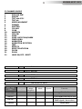
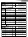
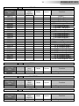
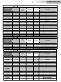
22- DMX PROTOCOL 23
23- 8 MOTORS CONTROL CARD 38
24- 8 MOTORS SLAVE CONTROL CARD 39
25- PAN & TILT CARD 40
26- CABLES RESEND CARD
27- DISPLAY CARD
28- LAMP ON-OFF CONTROL CARD
29- ROTATING GOBO WHEEL 41
30- FIXED GOBO WHEEL 42
31- COLOUR WHEEL 1 43
XR2000 SPOT CMY

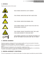
1- SYMBOLS
Graphic symbols used on this manual
2- GENERAL WARNING
Read the instruction contained in this user manual carefully, as they give important information
regarding safety during installation , use and maintenance.
The device is not for domestic use and must be installed by a qualified electrician or experienced
person.
Always disconnect the device from the mains before replacing the lamp.
The lamp must be replaced if it has been damaged or deformed by prolonged use or overheating.
The device must always be equipped with an efficient ground connection.
3- GENERAL WARRANTY CONDITIONS
The unit is guaranteed for 24 months from the date of purchase against manufacturing material defects.
THIS SYMBOL INDICATES A HOT SURFACE
THIS SYMBOL INDICATES ELECTRIC SHOCK RISK
THIS SYMBOL INDICATES GENERAL RISK
THIS SYMBOL MEANS “DO NOT PLACE THE UNIT ON
INFLAMMABLE SURFACES”
2M
THIS SYMBOL INDICATES THE MINIMUM DISTANCE TO
BE KEPT BETWEEN THE DEVICE AND THE LIT OBJECT
4
F
THIS SYMBOL MEANS “RADIATION FROM THIS LAMP
CAN CAUSE DAMAGE TO EYES AND SKIN”
!
UV
XR2000 SPOT CMY

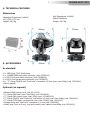
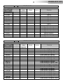
4- TECHNICAL FEATURES
Lamp
Lamp: Philips MSR Gold 700/2 Fastfit
Automatic switching ON of lamp in case of accidental switching OFF.
Lamp ON/OFF via DMX; Reset via DMX.
Optical group
Focus
Motorized focus
Iris
Motorized iris (16 bit)
Zoom
Motorized zoom (8°- 30°)
The XR2000 SPOT CMY is one of the most powerful moving heads in the 700W range.
The XR2000 SPOT CMY in fact delivers a massive 64.300 Lux at 5 m (8° beam angle), thanks to its
improved optical group and dichroic glass reflector, combined with a Philips MSR Gold 700/2 Fastfit lamp
(50.000 Lumens).
The XR2000 SPOT CMY is particularly suitable for all professional applications, both mobile (concerts,
shows, tours, special events) and fixed (clubs and other venues), requiring a light with extremely high
luminous output and versatility of functions.
The XR2000 SPOT CMY is also the ideal light for a vast range of applications in which quiet operation is
a priority, thanks to its silent ventilation system and silent pan/tilt operation.
The XR2000 SPOT CMY incorporates motorized focus; motorized iris; linear zoom (8°- 30°); a
sophisticated CMY colour synthesis system with 3 palettes for linear insertion, plus a colour wheel (7
colours + open); 2 gobo wheels: one customizable rotating gobo wheel (7 gobos) and one customizable
fixed gobo wheel (8 gobos); frost filter (soft edge); 3-facet rotating prism; animation wheel rotating in
both directions.
The 16 bit Pan/Tilt mechanism features an exclusive Super Speed function, and a locking system with
recessed buttons. Access to every feature of the internal menu is simple and direct, thanks to the new
user interface featuring a LCD backlit graphic display (128 x 64).
XR2000 SPOT CMY
(Cod. 03.MS008.EB.L)
• Electronic ballast 90-245V 50/60 Hz • Black finish
Also available with white finish (RAL 9003) on demand
64.300 Lux at 5 m (8° beam angle)
Dichroic glass reflector
5
XR2000 SPOT CMY

4- TECHNICAL FEATURES
Dimmer / shutter / strobo
Linear dimmer
Shutter
Strobe from 0,85 flash/sec to 6,75 flash/sec
Power saving mode (the lamp dims to 50% six seconds after shutter closure)
Colours
Gobos
2 gobo wheels: 1 rotating (7 indexable 16 bit gobos + open) and 1 fixed (8 gobos + open)
Extractable gobo holders for both wheels
Gobo change with synchronized blackout
Gobo scrolling; Gobo shake
Effects
Pan / Tilt
30 DMX channels (Default)
Internal operating system updatable via DMX
Connections
4 XLR connectors (3-pole In and Out; 5-pole In and Out) by Neutrik
POWERCONN connector by Neutrik
Power supply
Electronic ballast: 90 - 260 V (50/60 Hz)
Power consumption: 820 W
Standard accessories
2 x “C” GQuick clamps with “fastlock” connection
Thermal
Operating ambient temperature: -10° / 40°
Weight
CMY colour synthesis system + colour wheel (7 colours + open) with linear selection for perfect 2-colour
beams
Colour change with blackout sync; rainbow effect
Indexable prism rotating in both directions (3-facet)
Frost filter (soft edge)
Animation wheel rotating in both directions
Pan 540° (3,9 sec.); Tilt 270° (2,6 sec.); 16-bit resolution
Super Speed function; extremely smooth and precise movements even at the highest speeds
Pan / Tilt locking system with recessed buttons
Automatic Pan/Tilt repositioning in case of knocks
Interface
LCD backlit graphic display (128x64)
Power saving mode (the lamp dims to 50% six seconds after shutter closure)
44,5 Kg
6
XR2000 SPOT CMY

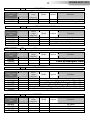
4- TECHNICAL FEATURES
Dimensions
5- ACCESSORIES
As standard
•1 x MSR Gold 700/2 Fastfit lamp
•1 x POWERCONN male cable connector (cod. 0520P014)
•1 x XLR 5 Pins male cable connector (cod. 0508B028)
•1 x XLR 5 Pins female cable connector (cod. 0508B027)
•2 x “C” Clamp GQUICK with “Fast Lock” connection 1/4 turn (max. load. 80Kg) (cod. 0521A014)
• User’s manual
Optional (on request)
• Wireless DMX receiver card (cod. 03.LA.012)
• “C” Clamp G60 black (max. load 50Kg) (cod. 0521A004)
• “C” Clamp G60 chrome (max. load. 50Kg) (cod. 0521A004.20)
• “C” Clamp GQUICK with “Fast Lock” connection 1/4 turn (max. load. 80Kg) (cod. 0521A014)
• “C” Clamp G100 black / professional (max. load. 200Kg) (cod. 0521A015)
• Omega clamp with “Fast Lock” connection 1⁄4 turn (cod. 02K00467)
• Safety wire (3mm x 60 cm), ring spring catch, max. capacity load 60Kg (cod. 0521A010)
Unit Dimensions (LxWxH)
568x510x826mm
Weight: 44,5 Kg
Packaging Dimensions (LxWxH)
670 x 550 x 730 mm
Weight: 49,5 Kg
7
XR2000 SPOT CMY
568mm
7 °2
0
m
826
m
459mm
510mm
636
m
m

6- IMPORTANT SAFETY INFORMATION
6.1 Fire prevention:
MSR Gold 700 Fastfit lamp
The use of any other alternative lamp is not recommended and will null and void the fixture's warranty.
-Never locate the fixture on any flammable surface.
-Minimum distance from flammable materials: 1.5 MT.
-Minimum distance from the closest illuminable surface: 2 MT.
-Replace any blown or damaged fuses only with those of identical value. Refer to the wiring diagram if
there is any doubt.
-Connect the projector to mains power via a thermal magnetic circuit breaker.
6.2 Prevention of electric shock:
-High voltage is present inside the unit. Unplug the unit prior to performing any function which involves
touching the inside of the moving head, including lamp replacement.
-The level of technology inherent in the XR2000 SPOT CMY requires the assistance of specialised
personnel for all servicing. Please refer to an authorised DTS service centre.
-A good earth connection is essential for proper functioning of the projector.
-Never connect the unit without proper earth connection.
-The fixture should be located in places with a good air ventilation.
6.3 Protection against ultraviolet radiation:
-Never turn on the lamp if any of the lenses, filters or ABS covering are damaged. Their respective
shielding functions will only operate efficiently if they are in perfect working order.
-Never look directly the lamp when it is on.
6.4 Safety:
-The projector should always be installed with bolts, clamps and other tools that are capable of
supporting the weight of the unit.
-Always use a second safety cable to sustain the weight of the unit in case of the failure of the main
fixing point.
-The external surface of the unit, at various points, may exceed 70°C. Never handle the unit until at
least 10 minutes have elapsed since the lamp was turned off.
-Always replace the lamp if any physical damage is evident.
-Never install the fixture in an enclosed area lacking sufficient air flow. The ambient temperature should
not exceed 40°C.
-A hot lamp may explode, so always wait for at least 10 minutes prior to attempting to replace the lamp.
-Always wear suitable hand protection when handling the lamp.
6.5 Level of protection against the penetration of solid and liquid objects:
-The projector is classified as an ordinary appliance and its protection level against the penetration of
solid and liquid objects is IP 20.
For outdoor use, D.T.S. reccomend the use of the dedicated raincovers:
XR2000 SPOT CMY uses a PHILIPS /2
• Raincover for XR2000 base (top) (cod. 03.MA009)
• Raincover for XR2000 base (bottom) (cod. 03.MA010)
2M
8
F
!
!
UV
XR2000 SPOT CMY

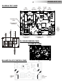
7- MOUNTING THE LAMPS
Warning: Switch off the unit before replacing the lamp.
1) Using a screwdriver, loose the 3 screws A, B, C, (photo 1) and remove the metal cover .
2) Insert the lamp (photo2).
3)Rotate the lamp 1/4 turn clockwise (photo 3 and 4).
The lamp used on XR2000 SPOT CMY is made in quartz glass and should be handled with care. Always
follow the instructions supplied in the lamp's packaging. Never touch the glass directly but use the tissue
provided in the lamp’s packaging. The lamp socket is not symmetrical.
DO NOT USE UNDUE FORCE ON THE GLASS. In case of difficulty, read again the instructions and repeat
the procedure.
4) Replace the metal cover and tighten the screws A,B,C, which were previously removed.
WARNING: Never look directly at the lamp when it’s lit.
Discharge lamps emits UV rays; radiation from this lamp can cause damage to eyes and skin.
7.1 Lamp alignment
Attention: we recommend to align the lamp in the optical system to avoid overheating of the dichroic
filters and other components inside the unit. The lamp alignment is also essential to obtain the
maximum unifirmity and luminous performance by the projection.
3 adjusters X, Y and
Z (photo 5)
you will have an evenly projected light beam, with no shadows or
zones wich are brighter than others.
Philips MSR Gold 700/2 Fastfit
Power 700W
Luminous flux 50,000 lm
Colour temperature 7.500°K
Lampbase PGJX50
Rated life 750 hours
PGJX50
1) Mount the fixture in an orientation so that it may be squarely projected onto a smooth white surface
no less than 3 meters away. 2) Using a console or the menu system, focus an open (white) beam onto
the surface and observe the beam. 3) Using a phillips-head screw driver, rotate the
until you achieve a uniform flat field.
When the lamp is correctly optimized,
Photo 2Photo 1 Photo 4Photo 3
Photo 5
9
Lamp
Alignment
UV
XR2000 SPOT CMY
Normal Hot Spot

8- VOLTAGE AND FREQUENCY
The XR2000 SPOT CMY with electronic ballast can operate at 90-260 VOLT 50 or 60 Hz.
9- INSTALLATION
XR2000 SPOT CMY may be either floor or ceiling mounted.
For floor mounting installations, the XR2000 SPOT CMY is supplied with four rubber mounting feet on
the base.
For ceiling mounted installations, we reccomend the use of appropriate clamps to fix the unit to the
mounting surface.
The supporting structure from which the unit is hung should be capable of bearing the weight of the
unit, as should any clamps used to hang it. The structure should also be sufficiently rigid so as not to
move or shake whilst the XR2000 SPOT CMY is moving.
Eight 1/4 turn Fast Locks connections placed in the base of the unit allow to fix the XR2000 SPOT CMY in
any position, by using the two Fast Lock “C” clamps provided in the box.
.
9.1- Safety cable
We recommend the use of a safety cable connected to the XR2000 SPOT CMY and to the suspension
truss in order to avoid the fixture accidentally falling should the main fixing point fail. Make sure that the
iron cable can bear the weight of the entire unit.
You may attach the safety cable to the two holes (A) located on the base of the fixture, as shown in the
picture below.
9.2- Protection against liquids
The projector contains electric and electronic components which should under no circumstances come
into contact with oil, water or any other liquid. The proper unit functioning would be compromised
should this occur.
A
!
240 mm
107 mm
10
XR2000 SPOT CMY

9.3- Movement
The projector has a maximum movement of 540° for Pan and 270° for Tilt. DO NOT place any
obstructions in the path of the projector's movement.
9.4- Risk of fire
Each fixture produces heat and must be installed in a well-ventilated place. The minimum recommended
distance from flammable material is 1 MT.
Minimum distance from the object being illuminated is 2 MT.
9.5- Forced ventilation
You will note, on inspection, that the unit features various air inlets and cooling fans located on both the
base and head of the fixture. These should, under no circumstances, be blocked or obstructed whilst the
projector is in operation.
Doing so could cause the fixture to seriously overheat thereby compromising its proper operation.
9.6- Ambient temperature
The projector should never be installed in places that lack a constant air flow. The ambient temperature
should NOT exceed 40°C.
10- MAINS CONNECTION
XR2000 SPOT CMY with electronic ballast operate at 90-260 VOLT 50-60 Hz.
Prior to connecting the unit to your mains supply,
ensure that the model in your possession correctly matches
the mains supply available. For connection purposes,
ensure that your plug is capable of supporting 8 amps at 230V,
Or 16 amps at 100-120 V
Strict adherence to regulatory norms is strongly recommended.
10.1- Protection
The use of a thermal magnetic circuit breaker is recommended for each XR2000 SPOT CMY.
A good earth connection is essential for the correct operation of the projector.
540°
270°
11
2M
F
!
WARNING
Do not place any object in the path
of the projector’s movement
!
XR2000 SPOT CMY
Electronic ballast
90-260V 50 / 60Hz

11- DMX SIGNAL CONNECTION
The unit operates using the digital DMX 512 (1990) signal. Connection between the mixer and the
projector or between projectors must be carried out using a two pair screened ø 0.5 mm cable and a XLR
5 or 3 pins connector. Ensure that the conductors do not touch each other. Do not connect the cable
ground to the XLR chassy
The plug housing must be isolated. Connect the mixer signal to the DMX IN projector plug and connect it
to the next projector by connecting the DMX OUT plug on the first projector to the DMX IN plug of the
second one.
This way, all the projectors are cascade connected.
NB. If the display showing the DMX address flashes, then one of the following errors has occurred:
- DMX signal not present
- DMX address not valid
- DMX reception problem
For Installations where long distance DMX cable connections are needed, we suggest to use a DMX
terminator.
The DMX terminator is a male XLR 3-5 pins connector with a 120 ohm resistor
Between pin 2 and 3.
The DMX terminator must be plugged into the last unit (DMX out panel connector) of the DMX line.
1
2
3
5
4
OUT
120 ohm
PIN 3
PIN 2
PLACE A 120 OHM RESISTOR BETWEEN PIN 2
AND 3 OF A MALE XRL CONNECTOR AND PLUG IT
INTO THE DMX OUT PANEL CONNECTOR OF THE
LAST UNIT CONNECTED TO THE DMX LINE
12
XR2000 SPOT CMY
5
3
4 2
1
1=GND
2=DATA-
3=DATA+
CONTROLLER
S TA N DA R D
D M X 5 1 2

11.1-DMX Addresses
XR2000 SPOT CMY can be controlled with 30 (default) or 22 DMX channels.
If you want to use the unit in 30 channels mode (default), set the following addresses on the mixer:
Projector 1 A001
Projector 2 A031 If you want to select the next projector, just add “30”
11.2-Selecting the DMX address
1) Press the UP-DOWN key until you reach the required DMX channel. The numbers on the display will
start to flash (but the new DMX address hasn't yet been set).
2) Press ENTER to confirm your selection. The numbers on the display will stop flashing and the
projector is now setted to the new DMX address.
TRICKS:
if you keep pushed the UP or DOWN keys, the channels are calculated more quickly and you get a
faster selection.
Projector 3 A061
….. A….
projector 6 A151
12 FIRMWARE UPDATING
Warning:
This procedure require a base knolewge of computer applications and Windows
Hyperterminal program.
To update the software version of the XR2000 SPOT CMY you need:
D.T.S. RED BOX interface (D.T.S. Code: 03.LA.008).
USB-DMX Driver for the D.T.S. RED BOX interface .
(The driver and the installation procedure are available in our web site www.dts-lighting.it)
Updating the software version.
Please follow the procedure below to perform the update:
1. Install the D.T.S. RED BOX USB-DMX driver on the PC you will use to update the unit software.
2. Connect the D.T.S. RED BOX interface to the PC by using a USB cable.
3. Connect the D.T.S. RED BOX interface to the fixture by using a DMX cable.
4. Download the new software version into the unit by using Windows Hyperterminal program.
It will be possible to download the software from the reserved area of D.T.S. web site:
www.dts-lighting.it.
Please refer to an authorised DTS service centre.
13
!
XR2000 SPOT CMY

14
XR2000 SPOT CMY
MAINS
Electronic ballast
90-260V 50 / 60Hz
DMX IN
DMX OUT
DISPLAY
MENU
ENTER
DOWN
UP
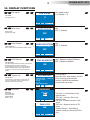
13- DISPLAY FUNCTIONS
DISPLAY FUNCTIONS
The XR2000 SPOT CMY display panel shows all the available functions . Using these functions, it is
possible to change some of the parameters and add some functions. Changing the DTS setting
can vary the functions of the unit so that it does not respond to the DMX 512 used to control it.
Carefully follow the instructions below before carrying out any variations or selections.
NOTE: the symbol shows which key has to be pushed to obtain the desired function.
DMX IN
DMX OUT
FUSE 16A T 5X20
PAN DIRECTION
NORMAL
MENU ENTER DOWN UP
Pan Direction
Up-Down
Up-DownENTER
PAN DIRECTION
This menu allows to set the Pan
movement.
Normal or Reversed
Pan movement Normal or Reversed
Default = Normal
ENTER
Menu
TILT DIRECTION
NORMAL
MENU ENTER DOWN UP
Tilt Direction
Up-Down
Up-DownENTER
TILT DIRECTION
This menu allows to set the Pan
movement.
Normal or Reversed
Tilt movement Normal or Reversed
Default = Normal
ENTER
Menu
PAN TILT SPEED
4
MENU ENTER DOWN UP
Pan Tilt Speed
Up-Down
Up-DownENTER
PAN TILT SPEED
Pan Tilt Speed control (1-4)
Pan Tilt Speed control
Default = 4
ENTER
Menu

15
XR2000 SPOT CMY
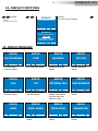
13- DISPLAY FUNCTIONS
MENU ENTER DOWN UP
Display
Up-Down
Up-DownENTER
Display Flip
ON THE GROUND (Default)
SUSPENDED
ENTER
Menu
DISPLAY FLIP / STAND BY / CONTRAST
Display Flip:
Reverses display's reading depending on the
mounting position
(On the ground or suspended).
Display Standby:
To turn off the display (after 5 seconds)
Or leave it always on.
Display Contrast:
Display contrast regulation (1-16)
FLIP
FLIP
ON THE GROUND
DISPLAY
MENU ENTER DOWN UP
FLIP
STANDBY
OFF
DISPLAY
MENU ENTER DOWN UP
FLIP
CONTRAST
8
DISPLAY
Display Standby
OFF = Display Standby disabled
(Default)
ON = Display goes OFF after 5
seconds
ENTER
Display Contrast
1-16 (Default = 8)
DMX MODE
30 channels
MENU ENTER DOWN UP
DMX Mode
Up-Down
Up-DownENTER
DMX mode
30 channels (Default)
22 channels
ENTER
Menu
DMX MODE
To select DMX mode :
30 channels or 22 channels
ENTER
ENTER
ENTER
BY DMX = ON / OFF via DMX (default)
ALWAYS ON = Forced ON
ALWAYS OFF = Forced OFF
RESET COUNTER = Lamp life time
reset
LAMP ADJUST =
To adjust the lamp
with no mixer connected.
It’s possible to set the parameters for
PAN-TILT and ZOOM
FLIP
LAMP
FLIP
LAMP
ADJUST
UP
UP
DOWN
DOWN
ENTER
ENTER
MENU
MENU
Up-DownENTER
LAMP
Lamp always ON, always OFF,
lamp ON-OFF selectable via DMX
And lamp life time reset
ADJUST
To adjust the lamp with no mixer
connected.
It’s possible to set the parameters for
PAN-TILT and ZOOM
Lamp
Up-Down
Menu
BY DMX
MENU ENTER DOWN UP
ENABLED = Reset via DMX enabled
(Default)
DISABLED = Reset via DMX disabled
NOW = Unit motors reset
RESET
Reset via DMX ENABLED / DISABLED
and unit reset
ENABLED
BY DMX
RESET
Reset
Up-Down
Up-DownENTER
ENTER
Menu

16
XR2000 SPOT CMY
13- DISPLAY FUNCTIONS
CMY BLACKOUT
ON
MENU ENTER DOWN UP
CMY Blackout
Up-Down
Up-DownENTER
ON = Blackout enabled (Default)
OFF = Blackout disabled
ENTER
Menu
CMY BLACKOUT
CMY filters blades inserted at 100% if the dimmer
remain closed for more than 5 seconds.
By activating this function, it will be possible to
reduce substantially any visible light reflection
coming out from the front lens when dimmer is
closed.
SYSTEM INFO
LAMP LIFE:0000H STRIKE:001
UNIT LIFE: 0010H
8M R.20
PT R.19
MODEL: XR2000 BEAM
MENU ENTER DOWN UP
System info
Up-Down
Up-DownENTER
SYSTEM INFO
Lamp life time, lamp strikes, unit life
time, 8 motors card software
version, Pan&Tilt card software
version and unit model
ENTER
Menu
SYSTEM INFO
Lamp life time, lamp strikes, unit life time, 8
motors card software version, Pan&Tilt card
software version and unit model
Reserved
Up-Down
Up-DownENTER
ENTER
Menu
RESERVED
Pan lock-Tilt lock
Pan free-Tilt free
System Reboot
(Code = 100)
RESERVED
000
MENU ENTER DOWN UP
ENTER CODE
FAN SPEED
5
MENU ENTER DOWN UP
Fan Speed
Up-Down
Up-DownENTER
Fan speed control
1-5 (Default = 5)
ENTER
Menu
FAN SPEED
Fan Speed control
GOBO ROTATION
OFF
MENU ENTER DOWN UP
Gobo Rotation
Up-Down
Up-DownENTER
ON
OFF = (Default)
ENTER
Menu
GOBO ROTATION
Gobo rotation control the Rotating speed of gobo
During gobo scrolling
AUTO FOCUS
OFF
MENU ENTER DOWN UP
Auto Focus
Up-Down
Up-DownENTER
ON
OFF = (Default)
ENTER
Menu
AUTO FUCOS
Automatic focusing
Pan Lock = Lock the Pan to the
desired value
Tilt Lock = Lock the Tilt to the
desired value
Pan Free = Remove power to Pan
motor
Tilt Free = Remove power to Tilt
motor
System Reboot = Unit Reboot
without needing of turning OFF the
unit
PAN LOCK
NO
MENU ENTER DOWN UP

17
XR2000 SPOT CMY
Default
Up-Down
Up-DownENTER
Default
To restore main settings
ENTER
Menu
DEFAULT
To restore main settings
DEFAULT
SURE?
MENU ENTER DOWN UP
RESTORE MAIN SETTINGS
DEFAULT
RESTORE MAIN SETTINGS
MENU ENTER DOWN UP
PRESS ENTER TO CONFORM
PRESS MENU TO CANCEL
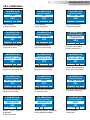
14- ERROR MESSAGES
13- DISPLAY FUNCTIONS
MENU ENTER DOWN UP
ERROR
COLOUR WHEEL
MENU ENTER DOWN UP
ERROR
CYAN
MENU ENTER DOWN UP
ERROR
MAGENTA
MENU ENTER DOWN UP
ERROR
YELLOW
MENU ENTER DOWN UP
ERROR
PAN
MENU ENTER DOWN UP
ERROR
TILT
MENU ENTER DOWN UP
ERROR
INTERNAL BUS
MENU ENTER DOWN UP
ERROR
DMX ADDRESS
COLOUR WHEEL
POSITION ERROR
CYAN POSITION ERROR MAGENTA POSITION
ERROR
YELLOW POSITION
ERROR
PAN REPOSITIONING
ENCODER ERROR
TILT REPOSITIONING
ENCODER ERROR
COMMUNICATION
PROBLEM BETWEEN 8
MOTORS CARD AND
PAN&TILT CARD
DMX ADDRESS
ERROR
MENU ENTER DOWN UP
ERROR
GOBO
MENU ENTER DOWN UP
ERROR
GOBO INDEX
MENU ENTER DOWN UP
ERROR
FIXED GOBO
MENU ENTER DOWN UP
ERROR
ANIMATION
GOBO WHEEL ERROR GOBO POSITION
ERROR
FIXED GOBO WHEEL
ERROR
ANIMATION WHEEL
ERROR

18
XR2000 SPOT CMY
15- HIDDEN MENU
For technical personnel only.
To operate this menu:
-Connect the projector to the DMX controller (DMX SIGNAL MUST BE CORRECTLY RECEIVED)
- Reset the XR2000 SPOT CMY (reset from the MENU, not from the DMX controller!).
- While reset is running, press the MENU and ENTER keys at the same time.
ELECTRONIC
CALIBRATION OF THE
MOTORS
RESET EEPROM.
RESET ALL SETTINGS
TO 128 VALUE
EXIT FROM HIDDEN
MENU
CALIBRATION
PAN
MENU ENTER DOWN UP
MOTORS ALIGNMENT
134
DEFAULT CAL
MENU ENTER DOWN UP
SET ALL MOTORS AT 128
EXIT TO MAIN
MENU ENTER DOWN UP
FAN SPEED WHEN
DIMMER CLOSED
FANS SPEED
MENU ENTER DOWN UP
ONLY AT MIN LAMP POWER
3
LAMP POWER WHEN
DIMMER CLOSED
MIN LAMP POW.
MENU ENTER DOWN UP
1=65% 100=100%
10
MENU ENTER DOWN UP
ERROR
IRIS
MENU ENTER DOWN UP
ERROR
EFFECT
MENU ENTER DOWN UP
ERROR
FOCUS
MENU ENTER DOWN UP
ERROR
ZOOM
IRIS ERROR
EFFECT WHEEL ERROR
FOCUS ERROR
ZOOM ERROR
MENU ENTER DOWN UP
ERROR
DIFFUSER
DIFFUSER ERROR

19
CYAN PATH ALIGNMENT
Cyan excursion setting
MAGENTA ZERO ALIGNMENT
Magenta zero position setting
YELLOW ZERO ALIGNMENT
Yellow zero position setting
15.1 Calibration
CALIBRATION
CYAN PATH
MENU ENTER DOWN UP
MOTORS ALIGNMENT
134
CALIBRATION
MAGENTA ZERO
MENU ENTER DOWN UP
MOTORS ALIGNMENT
167
CALIBRATION
YELLOW ZERO
MENU ENTER DOWN UP
MOTORS ALIGNMENT
141
MAGENTA PATH ALIGNMENT
Magenta excursion setting
CALIBRATION
MAGENTA PATH
MENU ENTER DOWN UP
MOTORS ALIGNMENT
151
YELLOW PATH ALIGNMENT
Yellow excursion setting
CALIBRATION
MENU ENTER DOWN UP
MOTORS ALIGNMENT
121
YELLOW PATH
PAN ALIGNMENT
To align Pan position
TILT ALIGNMENT
To align Tilt position
SHUTTER ALIGNMENT
To align Shutter blades
GOBO WHEEL INDEX ALIGNMENT
To align Gobo wheel Index
CYAN ZERO ALIGNMENT
Cyan zero position setting
IRIS ALIGNMENT
To align IRIS
CALIBRATION
PAN
MENU ENTER DOWN UP
MOTORS ALIGNMENT
134
CALIBRATION
TILT
MENU ENTER DOWN UP
MOTORS ALIGNMENT
167
CALIBRATION
SHUTTER
MENU ENTER DOWN UP
MOTORS ALIGNMENT
145
CALIBRATION
GOBO INDEX
MENU ENTER DOWN UP
MOTORS ALIGNMENT
141
CALIBRATION
IRIS
MENU ENTER DOWN UP
MOTORS ALIGNMENT
85
CALIBRATION
CYAN ZERO
MENU ENTER DOWN UP
MOTORS ALIGNMENT
162
GOBO WHEEL ALIGNMENT
To align Gobo wheel
CALIBRATION
GOBO
MENU ENTER DOWN UP
MOTORS ALIGNMENT
151
COLOUR WHEEL ALIGNMENT
To align Colour wheel
CALIBRATION
COLOUR WHEEL
MENU ENTER DOWN UP
MOTORS ALIGNMENT
151
G O B O F I X E D W H E E L
ALIGNMENT
To align Gobo wheel
CALIBRATION
FIXED GOBO
MENU ENTER DOWN UP
MOTORS ALIGNMENT
151
ANIMATION WHELL ALIGNMENT
To align ANIMATION WHEEL
CALIBRATION
ANIMATION
MENU ENTER DOWN UP
MOTORS ALIGNMENT
151
XR2000 SPOT CMY

20
Calibration mode
EFFECTS ALIGNMENT
To align EFFECTS
CALIBRATION
EFFECTS
MENU ENTER DOWN UP
MOTORS ALIGNMENT
85
DIFFUSER ALIGNMENT
To align DIFFUSER
CALIBRATION
DIFFUSER
MENU ENTER DOWN UP
MOTORS ALIGNMENT
85
FOCUS ALIGNMENT
To alignFOCUS
CALIBRATION
FOCUS
MENU ENTER DOWN UP
MOTORS ALIGNMENT
151
ZOOM ALIGNMENT
To align ZOOM
CALIBRATION
ZOOM
MENU ENTER DOWN UP
MOTORS ALIGNMENT
151
16- PAN & TILT SPEED (default: 4)
17- FAN SPEED ( default: 5)
You can set the PAN and TILT motors at high speed on your XR2000 SPOT CMY.
Press menu until you see PAN TILT SPEED.
Press ENTER and select a speed with UP-DOWN (there are 4 speeds). Confirm by pressing ENTER.
Fan speed regulation makes it possible to reduce fan noise. However, the ambient temperature must be
less than 35° C.
XR2000 SPOT CMY
La pagina sta caricando ...
La pagina sta caricando ...
La pagina sta caricando ...
La pagina sta caricando ...
La pagina sta caricando ...
La pagina sta caricando ...
La pagina sta caricando ...
La pagina sta caricando ...
La pagina sta caricando ...
La pagina sta caricando ...
La pagina sta caricando ...
La pagina sta caricando ...
La pagina sta caricando ...
La pagina sta caricando ...
La pagina sta caricando ...
La pagina sta caricando ...
La pagina sta caricando ...
La pagina sta caricando ...
La pagina sta caricando ...
La pagina sta caricando ...
La pagina sta caricando ...
La pagina sta caricando ...
La pagina sta caricando ...
La pagina sta caricando ...
La pagina sta caricando ...
La pagina sta caricando ...
La pagina sta caricando ...
La pagina sta caricando ...
-
 1
1
-
 2
2
-
 3
3
-
 4
4
-
 5
5
-
 6
6
-
 7
7
-
 8
8
-
 9
9
-
 10
10
-
 11
11
-
 12
12
-
 13
13
-
 14
14
-
 15
15
-
 16
16
-
 17
17
-
 18
18
-
 19
19
-
 20
20
-
 21
21
-
 22
22
-
 23
23
-
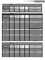 24
24
-
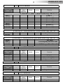 25
25
-
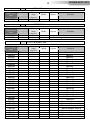 26
26
-
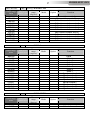 27
27
-
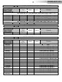 28
28
-
 29
29
-
 30
30
-
 31
31
-
 32
32
-
 33
33
-
 34
34
-
 35
35
-
 36
36
-
 37
37
-
 38
38
-
 39
39
-
 40
40
-
 41
41
-
 42
42
-
 43
43
-
 44
44
-
 45
45
-
 46
46
-
 47
47
-
 48
48


DTS XR2000 SPOT CMY Manuale utente
- Categoria
- Proiettori
- Tipo
- Manuale utente
in altre lingue
- English: DTS XR2000 SPOT CMY User manual