
TMD90TMD90
Dual Input
Digital
Thermometer
User Manual
•
Mode d'emploi
•
Bedienungshandbuch
•
Manuale d'Uso
•
Manual de uso
U.S. Service Center
Meterman Test Tools
1420 75th Street SW
Everett, WA 98203
Tel: 888-993-5853
Fax: 425-446-6390
Canadian Service Center
Meterman Test Tools
400 Britannia Rd. E. Unit #1
Mississauga, ON L4Z 1X9
Tel: 905-890-7600
Fax: 905-89-6866
European Correspondence Address*
Meterman Test Tools Europe
P.O. Box 1186
5602 BD Eindhoven
The Netherlands
*Correspondence only - no repair or replacement
available from this address. European customers
please contact your distributor.
Visit www.metermantesttools.com for
• Catalog
• Application notes
• Product specifications
• Product manuals
PN 2099366
September 2003
© Wavetek Meterman Test Tools.
All rights reserved. Printed in China.
Please Recycle
®
®
®
®

1
TMD90 Dual Input Thermometer
Contents
Safety Information..............................................................................2
Symbols Used in this Manual...........................................................2
Introduction........................................................................................3
Display and Controls...........................................................................4
Functions............................................................................................ 5
Auto Power Off ( Sleep Mode )......................................................... 5
Change Thermocouple Type............................................................. 5
Using the Pushbuttons.....................................................................6
RS-232 Output................................................................................. 7
Troubleshooting.................................................................................. 8
Replacing the Battery.......................................................................... 9
9 V ac Adapter ....................................................................................9
Repair............................................................................................... 10
WARRANTY...................................................................................... 11
Thermocouple Definitions................................................................. 11
Specifications................................................................................... 12
Additional Specifications................................................................... 12
English
Document Dimensions: 3 x 5 inches

2
Safety Information
• Place ONLY thermocouples in the thermocouple input.
• Make sure your meter is configured for the thermocouple type to
be used.
• Be sure the thermocouple you use can withstand the temperature
extreme it will be exposed to.
• Properly maintain the meter and calibrate it regularly
• Use the thermometer only as specified in this manual, or the
protection provided by the thermometer might be impaired.
• Replace the battery as soon as BAT appears to avoid false readings
that can lead to electric shock and injury.
Warning
Supplied thermocouple is not intended for contact
with liquids or live electrical circuits.
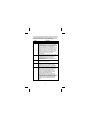
Symbols Used in this Manual
Dangerous Voltage Refer to the manual
Double insulated Earth Ground
Complies with EU
directives

3
Introduction
The Model TMD90 dual input thermometer accepts Type K, J, T, R, S,
and E thermocouples. With a triple display screen to view measurement
results and relative time clock. Optional RS-232 software and cable
allows collection of real time data to a PC for further analysis or
reports.
TMD90 displays all LCD (liquid crystal display) segments for
approximately 3 seconds when it is first turned on and then provides
information on any connected thermocouples. Numerous viewing
combinations are available. The LCD is divided into three distinct
sections; one large (Primary) top screen and two smaller bottom
screens (Secondary and Relative Clock).
The three display areas are continually updated with the temperature
measurements and relative time information. There are several options
regarding how and what information is presented on the LCD.
• Temperature readings are easily toggled between Fahrenheit and
Celsius.
• A backlight illuminates the LCD for viewing in low light areas.
• The button will freeze the upper display data while allowing
the lower displays to continue updating Information.
• A low battery indicator is also displayed as appropriate.
• The meter defaults to the last mode selected when turned off.
Note: If no thermocouples are connected, four dashes(----) appear in
the temperature display.
Box Contents
TMD90 Thermometer 1
Type K thermocouple probe 1
Users Manual 1
Hard plastic carry case 1
9 V battery (installed) 1

4
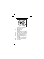
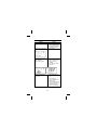
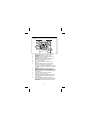
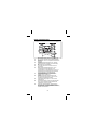
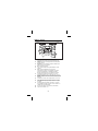
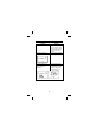
Display and Controls
10 (T2)
10 (T1)
5
4
32
6
7
1
8
9
11
6
12
13
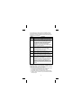
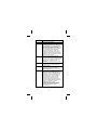
REC Relative clock is active for recording min and max
temperature occurences or for time stamp purposes.
MAX/MIN Maximum or minimum temperature
measurements are being monitored.
HOLD/REL Freezes primary display or establishes a relative
zero for the primary display information.
BAT Low battery indicator.
°C °F Displays temperature in either degrees Celsius or
degrees Fahrenheit.
T1-T2 Toggles screen niformation from T1 (Primary)/ T 2
(Secondary) to T2 (Primary) / T1 (Secondary) ,then to T 1-T 2
(Differential) on Primary and alternating T1/T2 temperatures
on Secondary display.
Primary data display. Displays T1, T2, or T1-T2( temperature
differential -TD ) or a relative zero of T1, T2, or TD.
KJTRSE Selects proper input reference for thermocouple in
use. T1 and T2 must be the same thermocouple type.
Secondary data display. Displays T2,T1 or T1 and T2
temperatures.
Thermocouple input. Positive and negative polarized plugs for
the thermocouple probes used ( Blade type ); T1 on the left
,T2 on the right.
Relative clock display. Displays time in hours, minutes, and
seconds (HHMMSS) when REC is pressed and the relative
time that MIN or MAX data was recorded.
RS-232 output port. Optional software and cable – PN
TM-SW.
AC to DC converter input.

5
Caution
Read all Safety Information before using this
thermometer.
Functions
Auto Power Off (Sleep Mode)
The TMD90 shuts off automatically approximately 20 minutes after
being turned on. For recording or operating over longer periods of time
you can disable the sleep mode by pressing and
simultaneously while power on. When "n" then appear in the center of
the screen you can release the On. Auto power off is disabled when you
turn off the meter.
Change Thermocouple Type
Press and simultaneously for 2 or more seconds until K
appears. Press the button the type of probe cycles through K
(the default), J, T, R, S, and E types. The current mode is displayed on
the left side of the LCD. press , an "S" will appear in the center of
the screen.

6
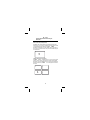
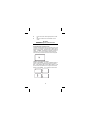
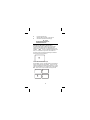
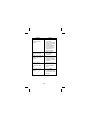
Using the Pushbuttons
The display defaults to the mode last used. For your convenience the
meter defaults to the settings used during the last operation.
˚C ˚F
HOLD
REL
REC
T
1 T2

7
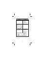
Use the pushbuttons to control operation of the TMD90. The table
assumes the TMD90 has been powered on with two thermocouples
installed and is set to display (default) T1 on the primary display, type
K thermocouple, and Record off.
Button Description
Turns the meter on and off.
Press and release HOLD/REL and the Primary display
(T1, T2, or T1-T2) freezes with HOLD displayed on top;
Press for two or more seconds REL appears on top of
LCD and the REL Primary display indicates the relative
zero. Relative zero causes the value of the primary
display to show as "000.0" , then only the amount of
temperature change will be indicated. Relative
temperatures can be recorded. Press HOLD/REL again
and the unit returns to default.
Press momentarily and the Primary display changes to
T2 (Secondary screen displays T1); press momentarily
again and it displays T1-T2; Secondary display
alternates between T1 and T2; Press momentarily again
and the instrument returns to default.
Press momentarily and the backlight illuminates for
approximately 30 seconds then turns off.
Press momentarily and the unit toggles between
Fahrenheit (the default) and Celsius temperatures; The
current mode is indicated on the right side of the LCD.
Press momentarily and the Relative Clock starts in the
lower right screen. All other button functions are locked
out except Power and Backlight. T1, T2, or T1-T2 is
displayed on the Primary screen; The Secondary screen
continues to update. Press momentarily again and the
unit cycles through MAX and MIN (Maximum and
Minimum recorded temperatures) and back to current
temperature; The record mode is displayed on the LCD.
Press and hold for three seconds to turn off the record
function.
RS-232 Output
With optional software and cable, P/N TM-SW, the TMD90 can output
measurement results to a computer with operating systems of Window
95/98/NT/2000/XP/ME. Features of the software:
• Record up to 16,000 sample readings with real-time clock memory.
• Programmable sample interval from 1 sec to 3,600 sec.
• User defined maximum and minimum alarm settings.
• Allow further analysis by downloading data to computer program.
• All data is saved in .txt format for easy transformation into another
software program.

8
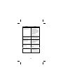
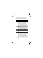
Troubleshooting
Problem Solution
Thermometer does not turn
on.
• Check battery voltage and
replace discharged battery.
• Verify that battery clips grip
the battery post tightly.
Dashes appear in the T1 and
T2 data screens.
• Insert missing
thermocouple.
Dashes appear in T1 and/or T2
data screens with
thermocouples inserted.
• Measure resistance of
thermocouples to ensure
they are not broken
internally.
• Clean the thermocouple
and restart.
Temperature drifts from a
known value in a controlled
environment
• Verify that thermocouple
type matches the displayed
icon.
• Clean and dry the
thermocouple blades and
allow to air dry.
• Confirm temperature with a
known good thermocouple.
Replace the defective
thermocouple if required.

9
Problem Solution
Relative clock does not start
when you push the
button.
• Verify that the
thermocouple is inserted
correctly.
Dashes appear during a review
of the maximum recorded
value.
• Thermocouple is not
acknowledged. Check for
intermittent or momentary
thermocouple removal.
Data continues to update after
you press the button.
• Check for HOLD icon on
the display. Press
button firmly.
Instrument turns off while
recording.
• Press and
simultaneously before
power on to disable the
Auto power off feature.
Replacing the Battery
Replace the 9 V battery when:
• BAT appears on the right side of the display.
• The meter will not turn on.
• BAT appears when you turn on the backlight.
Even if the battery was recently replaced, check the voltage level if there
is no response from the meter.
To replace the battery
1. Remove all thermocouples from the top of the meter.
2. Lay the instrument face down on a clean, flat surface.
3. Loosen the screw and remove the battery door.
4. Replace the battery.
5. Replace the battery door and tighten the screw.
Remove the battery if you do not plan to use the meter for a month or
more. Do not leave the battery in a meter that may be exposed to
temperature extremes.
9 V ac Adapter
For long term measurement recording, a 9 V AC adapter can be used in
place of the battery. This can be purchased at any electronics store
using these specs: Miniature power plug with inner conductor positive
and outer conductor negative, 500 mA current rating. The 9 V battery
can be left in the TMD90 when using the AC adapter.

10
Repair
All test tools returned for warranty or non-warranty repair or for
calibration should be accompanied by the following: your name,
company’s name, address, telephone number, and proof of purchase.
Additionally, please include a brief description of the problem or the
service requested and include the test leads with the thermometer.
Non-warranty repair or replacement charges should be remitted in the
form of a check, a money order, credit card with expiration date, or a
purchase order made payable to Meterman Test Tools.
In-Warranty Repairs and Replacement – All Countries
Please read the warranty statement that follows, and check your
batteries and fuses before requesting repair. During the warranty
period any defective test tool can be returned to your Meterman Test
Tools distributor for an exchange for the same or like product. Please
check the “Where to Buy” section on www.metermantesttools.com for
a list of distributors near you. Additionally, in the United States and
Canada In-Warranty repair and replacement units can also be sent to a
Meterman Test Tools Service Center (see below for address).
Non-Warranty Repairs and Replacement – US and Canada
Non-warranty repairs in the United States and Canada should be sent to
a Meterman Test Tools Service Center. Call Meterman Test Tools or
inquire at your point of purchase for current repair and replacement
rates.
In USA In Canada
Meterman Test Tools Meterman Test Tools
1420 75th Street SW 400 Britannia Rd. E. Unit #1
Everett, WA 98203 Mississauga, ON L4Z 1X9
Tel: 888-993-5853 Tel: 905-890-7600
Fax: 425-446-6390 Fax: 905-890-6866
Non-Warranty Repairs and Replacement – Europe
European non-warranty units can be replaced by your Meterman Test
Tools distributor for a nominal charge. Please check the “Where to
Buy” section on www.metermantesttools.com for a list of distributors
near you.
European Correspondence Address*
Meterman Test Tools Europe
P.O. Box 1186
5602 BD Eindhoven
The Netherlands
*(Correspondence only – no repair or replacement available from this
address. European customers please contact your distributor.)

11
WARRANTY
The TMD90 Dual Input Thermometer is warranted against any defects
of material or workmanship within a period of one (1) year following
the date of purchase of the thermometer by the original purchaser or
original user. Any thermometer claimed to be defective during the
warranty period should be returned with proof of purchase to an
authorized Meterman Test Tools Service Center or to the local
Meterman Test Tools dealer or distributor where your thermometer
was purchased. See Repair section for details. Any implied warranties
arising out of the sale of a Meterman Test Tools thermometer,
including but not limited to implied warranties of merchantability and
fitness for a particular purpose, are limited in duration to the above
stated one (1) year period. Meterman Test Tools shall not be liable for
loss of use of the thermometer or other incidental or consequential
damages, expenses, or economical loss or for any claim or claims for
such damage, expenses or economical loss. Some states do not allow
limitations on how long implied warranties last or the exclusion or
limitation of incidental or consequential damages, so the above
limitations or exclusions may not apply to you. This warranty gives you
specific legal rights, and you may also have other rights which vary
from state to state.
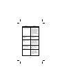
Thermocouple Definitions
Type Alloy Alloy
J
Iron
Fe
Copper-Nickel
(Constantan)
Cu-Ni
K
Nickel-Chromium
(Chromel)
Ni-Cr
Nickel-Aluminum
Ni-AL
R
Platinum-13% Rhodium
Pt-13% Rh
Platinum
Pt
S
Platinum-10% Rhodium
Pt-10% Rh
Platinum
Pt
T
Copper
Cu
Copper-Nickel
(Constantan)
Cu-Ni
E
Nickel-Chromium
(Chromel)
Ni-Cr
Copper-Nickel
(Constantan)
Cu-Ni

12
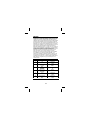
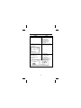
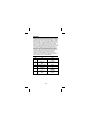
Specifications
T/C Type Range Resolution Accuracy
K
-200 to 650 °C0.1 °C
651 to 1370 °C1.0 °C
(0.1% rdg + 0.7 °C)
-328 to 1000 °F0.1 °F
1001 to 2498 °F1.0 °F
(0.1% rdg + 1.4 °F)
J -200 to 500 °C0.1 °C
501 to 760 °C1.0 °C
(0.1% rdg + 0.7 °C)
-328 to 940 °F0.1 °C
941 to 1400 °F1.0 °F
(0.1% rdg + 1.4 °F
T
-200 to 390 °C0.1 °C (0.1% rdg + 0.7 °C)
-328 to 730 °F0.1 °F (0.1% rdg + 1.4 °F)
R/S
0 to 1000 °C0.1 °C
1001 to 1760 °C1.0 °C
(0.3% rdg + 0.7 °C)
32 to 1000 °F0.1 °F
1001 to 3200 °F1.0 °F
(0.1% rdg + 1.4 °F)
E
-200 to 380 °C0.1 °C
381 to 736 °C1.0 °C
(0.3% rdg + 0.7 °C)
-328 to 720 °F0.1 °F
721 to 1832 °F1.0°F
(0.1% rdg + 1.4 °F)
Additional Specifications
OPERATING CONDITIONS
0 to 50 °C (32 to 122 °F) at 0 to 85 % relative humidity
(non-condensing)
Ambient Coefficient
0 to 18 °C and 28 to 50 °C (Ambient temperatures) For each °C
ambient below 18 °C or above 28 °C, add the following tolerance into
the accuracy spec: 0.01% of reading +0.03 °C (0.01% of reading
+0.06 °F).

1
Thermomètre à double entrée TMD90
Table des matières
Consignes de sécurité..........................................................................2
Symboles utilisés dans ce mode d'emploi..........................................2
Introduction.........................................................................................3
Affichage et commandes......................................................................4
Fonctions.............................................................................................5
Arrêt automatique (mode de veille)....................................................5
Changer le type de thermocouple.......................................................5
Utilisation des boutons poussoirs......................................................6
Sortie RS-232...................................................................................8
Dépannage...........................................................................................9
Remplacement de la pile ....................................................................11
Adaptateur secteur de 9 V ..................................................................11
Réparation.........................................................................................12
GARANTIE.........................................................................................13
Définitions des thermocouples...........................................................13
Spécifications....................................................................................14
Autres caractéristiques.......................................................................14
Français
Français

2
Consignes de sécurité
• Placer UNIQUEMENT des thermocouples dans l’entrée de
thermocouple.
• S’assurer que l’appareil est configuré pour le type de thermocouple
concerné.
• Vérifier que le thermocouple utilisé peut supporter les températures
extrêmes auxquelles il sera exposé.
• Entretenir l’appareil avec soin et l’étalonner régulièrement
• Utilisez uniquement le thermomètre, en respectant les indications
de ce manuel afin de ne pas entraver sa protection intégrée
• Remplacer la pile dès l’apparition de l'indicateur de pile faible
apparaît pour éviter les mesures erronées qui posent des risques
d'électrocution et de blessures.
Avertissement
Le thermocouple fourni n’est pas conçu pour être en
contact avec des liquides ou des circuits électriques
sous tension.
Symboles utilisés dans ce mode d'emploi
Tension dangereuse
Se reporter au mode
d’emploi
Double isolation Prise de terre
Conforme aux
directives de l’UE

3
Introduction
Le thermomètre à entrée double modèle TMD90 accepte les
thermocouples de types K, J, T, R, S et E. Il est doté d’un écran à triple
affichage pour visualiser les résultats de mesure et l’horloge en temps
relatif. Le logiciel et le câble optionnel RS-232 permettent de recueillir
les données en temps réel vers un PC afin de les analyser ou de créer
ultérieurement des rapports.
Le TMD90 affiche tous les segments LCD (affichage à cristaux liquides)
pendant environ 3 secondes lors du démarrage avant de fournir les
informations sur tous les thermocouples connectés. Diverses
combinaisons d’affichage sont possibles. L’écran LCD est divisé en
trois sections distinctes ; une fenêtre principale (affichage primaire) en
haut et deux fenêtres plus petites en bas (affichage secondaire et
horloge relative).
Les trois zones d’affichage sont actualisées en permanence avec les
mesures de température et les informations de temps relatif. Plusieurs
options permettent de configurer la présentation et le type des
informations apparaissant sur l’écran LCD.
• Les relevés de température basculent facilement entre les unités
Fahrenheit et Celsius.
• Un rétroéclairage illumine l’écran LCD pour les lectures en zones
faiblement éclairées.
• Le bouton gèle l’affichage de la fenêtre supérieure des
données tout en permettant la mise à jour des informations dans
les fenêtres du bas.
• Un indicateur de pile faible apparaît également le cas échéant.
• L’appareil adopte par défaut le dernier mode qui était sélectionné à
la mise hors tension.
Remarque : Si aucun thermocouple n’était connecté, quatre tirets (----)
apparaissent sur l’affichage des températures.
Contenu du coffret
Thermomètre TMD90 1
Sonde de thermocouple de type K 1
Mode d’emploi 1
Boîtier de transport en plastique rigide 1
Pile de 9 V (installée) 1

4
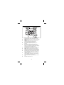
Affichage et commandes
10 (T2)
10 (T1)
5
4
32
6
7
1
8
9
11
6
12
13
REC L’horloge relative est active pour enregistrer les
incidences de température min et max ou pour
l’horodatage.
MAX/MIN Les mesures de température minimum ou
maximum actuellement contrôlées.
HOLD/REL Gèle l’affichage primaire ou établit un zéro
relatif pour les informations qu’elle contient.
BAT Témoin de pile faible.
°C °F Affiche la température en degrés Celsius ou
Fahrenheit.
T1-T2 Bascule entre l’affichage des informations T1
(primaire)/ T 2 (secondaire) et T2 (primaire) / T1
(secondaire), puis entre T 1-T 2(différentiel) sur l’affichage
principal et les températures alternées T1/T2 sur la fenêtre
secondaire.
Affichage des données primaires. Affiche T1, T2 ou T1-T2(
différentiel de température -TD ) ou un zéro relatif de T1, T2 ou TD.
KJTRSE Sélectionne la référence d’entrée appropriée pour le
thermocou ple utilisé. T1 et T2 doivent avoir le même type
de thermocouple.
Affichage des données secondaires. Affiche les
températures de T2,T1 ou de T1 et T2.
Entrée de thermocouple. Fiches à polarités positive et négative
pour les sondes de thermocouple utilisées (type de lame) ; T1 à
gauche ,T2 à droite.
Affichage d’horloge relative. Affiche l’heure en heures,
minutes et secondes (HHMMSS) à la pression de la touche
REC, et l’heure relative de l’enregistrement des résultats
MIN ou MAX.

5
Port de sortie RS-232. Câble et logiciel optionnel – Réf.TM-
SW.
Entrée du convertisseur de courant alternatif à courant
continu.
Attention
Lire toutes les consignes de sécurité avant d’utiliser
ce thermomètre.
Fonctions
Arrêt automatique (mode de veille)
Le TMD90 s’arrête automatiquement environ 20 minutes après sa mise
sous tension. Pour effectuer des enregistrements ou utiliser l’appareil
pendant de longues périodes, désactivez le mode de veille en appuyant
sur et sur simultanément avec l’appareil sous tension. A
l’apparition de « n » au centre de l’affichage, relâchez la touche On.
L’arrêt automatique est désactivé à la mise hors tension de l’appareil.
Changer le type de thermocouple
Appuyez sur le bouton et sur simultanément pendant au
moins 2 secondes jusqu’à l’apparition de K. Appuyez sur le bouton
et faites défiler les types de sondes, de K (par défaut) à J, T, R,
S, et E. Le mode actuel s’affiche dans le coin gauche de l’écran LCD.
Appuyez sur le bouton , un « S » apparaît au centre de l’écran.

6
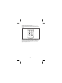
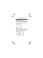
Utilisation des boutons poussoirs
L’affichage adopte par défaut le dernier mode utilisé. Pour plus de
commodité, l’appareil utilise les paramètres utilisés pendant la dernière
opération.
˚C ˚F
HOLD
REL
REC
T
1 T2
Utilisez les boutons poussoirs pour contrôler le fonctionnement du
TMD 90. Dans le tableau suivant, on suppose que le TMD90 a été mis
sous tension avec deux thermocouples installés et qu’il est réglé pour
afficher (par défaut) T1 sur l’affichage primaire, le thermocouple de
type K et l’enregistrement inactif.

7
Bouton Description
Active ou désactive l’appareil.
Appuyez sur HOLD/REL, puis relâchez et
l'affichage principal (T1, T2 ou T1-T2) se fige
avec HOLD affiché en haut. Maintenez appuyer
pendant au moins deux secondes et REL
apparaît en haut de l'écran à cristaux liquides et
l'affichage principal REL indique le zéro relatif.
Le zéro relatif oblige l'affichage principal à
afficher la valeur « 000.0 », ensuite, seul le
changement de température sera indiqué. Les
températures relatives peuvent être enregistrées.
Appuyez à nouveau sur HOLD/REL et l'appareil
reprend sa valeur par défaut.
Une pression momentanée et l’affichage
primaire affiche T2 (la fenêtre secondaire affiche
T1) ; une nouvelle pression momentanée permet
d’afficher T1-T2 ; la fenêtre secondaire bascule
entre T1 et T2 ; une dernière pression
momentanée et l’instrument revient au réglage
par défaut.
Une pression momentanée et le rétroéclairage
s’allume pendant une trentaine de secondes
avant de s’éteindre.
Une pression momentanée et l’appareil bascule
entre les températures en Fahrenheit (par
défaut) et Celsius ; le mode courant est indiqué
à droite sur l’écran LCD.
Une pression momentanée et l’horloge relative
(REC) démarre dans la fenêtre inférieure droite,
s’affiche dans le coin supérieur gauche de
l’écran LCD – Toutes les autres fonctions sont
verrouillées en dehors de l’alimentation et du
rétroéclairage. T1, T2 ou T1-T2 s’affiche sur
l’affichage primaire ; la fenêtre secondaire
continue d’être actualisée. Une nouvelle
pression momentanée et l’appareil répète les
valeurs MAX et MIN (températures maximum et
minimum enregistrées) et revient à la
température courante ; le mode
d’enregistrement apparaît sur l’écran LCD.
Maintenez la touche enfoncée pendant trois
secondes pour désactiver la fonction
d’enregistrement.
La pagina si sta caricando...
La pagina si sta caricando...
La pagina si sta caricando...
La pagina si sta caricando...
La pagina si sta caricando...
La pagina si sta caricando...
La pagina si sta caricando...
La pagina si sta caricando...
La pagina si sta caricando...
La pagina si sta caricando...
La pagina si sta caricando...
La pagina si sta caricando...
La pagina si sta caricando...
La pagina si sta caricando...
La pagina si sta caricando...
La pagina si sta caricando...
La pagina si sta caricando...
La pagina si sta caricando...
La pagina si sta caricando...
La pagina si sta caricando...
La pagina si sta caricando...
La pagina si sta caricando...
La pagina si sta caricando...
La pagina si sta caricando...
La pagina si sta caricando...
La pagina si sta caricando...
La pagina si sta caricando...
La pagina si sta caricando...
La pagina si sta caricando...
La pagina si sta caricando...
La pagina si sta caricando...
La pagina si sta caricando...
La pagina si sta caricando...
La pagina si sta caricando...
La pagina si sta caricando...
La pagina si sta caricando...
La pagina si sta caricando...
La pagina si sta caricando...
La pagina si sta caricando...
La pagina si sta caricando...
La pagina si sta caricando...
La pagina si sta caricando...
La pagina si sta caricando...
La pagina si sta caricando...
La pagina si sta caricando...
La pagina si sta caricando...
La pagina si sta caricando...
La pagina si sta caricando...
La pagina si sta caricando...
La pagina si sta caricando...
-
 1
1
-
 2
2
-
 3
3
-
 4
4
-
 5
5
-
 6
6
-
 7
7
-
 8
8
-
 9
9
-
 10
10
-
 11
11
-
 12
12
-
 13
13
-
 14
14
-
 15
15
-
 16
16
-
 17
17
-
 18
18
-
 19
19
-
 20
20
-
 21
21
-
 22
22
-
 23
23
-
 24
24
-
 25
25
-
 26
26
-
 27
27
-
 28
28
-
 29
29
-
 30
30
-
 31
31
-
 32
32
-
 33
33
-
 34
34
-
 35
35
-
 36
36
-
 37
37
-
 38
38
-
 39
39
-
 40
40
-
 41
41
-
 42
42
-
 43
43
-
 44
44
-
 45
45
-
 46
46
-
 47
47
-
 48
48
-
 49
49
-
 50
50
-
 51
51
-
 52
52
-
 53
53
-
 54
54
-
 55
55
-
 56
56
-
 57
57
-
 58
58
-
 59
59
-
 60
60
-
 61
61
-
 62
62
-
 63
63
-
 64
64
-
 65
65
-
 66
66
-
 67
67
-
 68
68
-
 69
69
-
 70
70


Wavetek 90 Manuale utente
- Tipo
- Manuale utente
- Questo manuale è adatto anche per
in altre lingue
- English: Wavetek 90 User manual
- français: Wavetek 90 Manuel utilisateur
- español: Wavetek 90 Manual de usuario
- Deutsch: Wavetek 90 Benutzerhandbuch
