
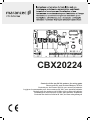
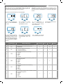
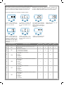
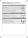
Control unit for two 24 Vdc motors, for swing gates
Steuergerät für zwei Drehtor-Motoren 24 Vdc
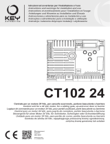
Centrale per due motori 24 Vdc, per cancelli a battente
Logique de commande pour deux moteurs 24 Vdc, pour portails battants
Central para dos motores de 24 Vdc para puertas de batiente
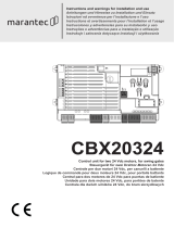
Unidade para dois motores 24 Vdc, para portões de batente
Centrala dla dwóch silników 24 Vdc, do bram skrzydłowych
Istruzioni ed avvertenze per l’installazione e l’uso
Instructions and warnings for installation and use
Instrucciones y advertencias para su instalación y uso
Anleitungen und Hinweise zu Installation und Einsatz
Instruções e advertências para a instalação e utilização
Instructions et avertissements pour l’installation et l’usag
UP
+ -
MENU
SBS
DOWN
(RADIO)
CBX20224
Control unit for two 24 Vdc motors, for swing gates
Steuergerät für zwei Drehtor-Motoren 24 Vdc
Centrale per due motori 24 Vdc, per cancelli a battente
Logique de commande pour deux moteurs 24 Vdc, pour portails battants
Central para dos motores de 24 Vdc para puertas de batiente
Unidade para dois motores 24 Vdc, para portões de batente
Centrala dla dwóch silników 24 Vdc, do bram skrzydłowych
Motoriduttore interrato
Under grounded gear motor
Motoreducteur enterré
Motorreductor interrado
Unrterflur-Drehtorantrieb
Motorredutor interrado
Podziemny motoreduktor
UNDER
Istruzioni ed avvertenze per l’installazione e l’uso
Instructions and warnings for installation and use
Instrucciones y advertencias para su instalación y uso
Anleitungen und Hinweise zu Installation und Einsatz
Instruções e advertências para a instalação e utilização
Instructions et avertissements pour l’installation et l’usage
Management
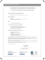
System
ISO 9001:2008
www.tuv.com
ID 9105043769

2
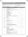
EN
1
2
3
4
5
6
7
8
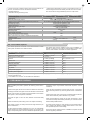
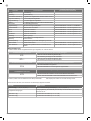
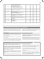
Safety warnings
2.1
2.2
2.3
2.4
4.1
4.2
4.3
4.4
4.5
5.1
5.2
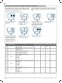
Product Introduction
Description of the control unit
Description of the connections
Models and technical characteristics
List of cables required
Preliminary Checks
Installing the Product
Electric connections
Display during normal operation
Autolearning of the travel stroke
Transmitter learning procedure
Customising the system - BASIC MENU
Testing and commissioning
Testing
Commissioning
Further details - ADVANCED MENU
Instructions and warnings for the
nal user
EC declaration of conformity
pag. 3
pag. 4
pag. 4
pag. 4
pag. 4
pag. 5
pag. 5
pag. 6
pag. 6
pag. 7
pag. 9
pag. 11
pag. 12
pag. 13
pag. 13
pag. 13
pag. 14
pag. 16
pag. 115
TABLE OF CONTENTS

3
EN
1 - SAFETY WARNINGS
ATTENTION !
ATTENTION !
ATTENTION !
ATTENTION !
ORIGINAL INSTRUCTIONS - important safety instructions.
Compliance with the safety instructions below is important for
personal safety. Save these instructions.
Read the instructions carefully before proceeding with installation.
The design and manufacture of the devices making up the
product and the information in this manual are compliant with
current safety standards. However, incorrect installation or
programming may cause serious injury to those working on or
using the system. Compliance with the instructions provided
here when installing the product is therefore extremely impor-
tant.
If in any doubt regarding installation, do not proceed and contact the
Marantec Technical Service for clarications.
Under European legislation, an automatic door or gate system
must comply with the standards envisaged in the Directive
2006/42/EC (Machinery Directive) and in particular standards
EN 12453; EN 12635 and EN 13241-1, which enable declaration
of presumed conformity of the automation system.
Therefore, nal connection of the automation system to the electri-
cal mains, system testing, commissioning and routine maintenance
must be performed by skilled, qualied personnel, in observance of
the instructions in the “Testing and commissioning the automation
system” section.
The aforesaid personnel are also responsible for the tests required
to verify the solutions adopted according to the risks present, and
for ensuring observance of all legal provisions, standards and regu-
lations, with particular reference to all requirements of the EN12453
standard which establishes the test methods for testing door and
gate automation systems.
Before starting installation, perform the following checks and
assessments:
ensure that every device used to set up the automation system is
suited to the intended system overall. For this purpose, pay special
attention to the data provided in the “Technical specications” sec-
tion. Do not proceed with installation if any one of these devices is
not suitable for its intended purpose;
check that the devices purchased are sucient to guarantee system
safety and functionality;
perform a risk assessment, including a list of the essential safety
requirements as envisaged in Annex I of the Machinery Directive,
specifying the solutions adopted. The risk assessment is one of the
documents included in the automation system’s technical le. This
must be compiled by a professional installer.
Considering the risk situations that may arise during instal-
lation phases and use of the product, the automation system
must be installed in compliance with the following safety pre-
cautions:
never make modications to any part of the automation system
other than those specied in this manual. Operations of this type
can only lead to malfunctions. The manufacturer declines all liability
for damage caused by unauthorised modications to products;
if the power cable is damaged, it must be replaced by the manufac-
turer or its after-sales service, or in all cases by a person with similar
qualications, to prevent all risks;
do not allow parts of the automation system to be immersed in water
or other liquids. During installation ensure that no liquids are able to
enter the various devices;
should this occur, disconnect the power supply immediately and
contact a Marantec Service Centre. Use of the automation system
in these conditions may cause hazards;
never place automation system components near to sources of heat
or expose them to naked lights. This may damage system compo-
nents and cause malfunctions, re or hazards;
all operations requiring opening of the protective housings of va-
rious automation system components must be performed with the
control unit disconnected from the power supply. If the disconnect
device is not in a visible location, ax a notice stating: “MAINTE-
NANCE IN PROGRESS”:
connect all devices to an electric power line equipped with an
earthing system;
the product cannot be considered to provide eective protection
against intrusion. If eective protection is required, the automation
system must be combined with other devices;
the product may not be used until the automation system “commis-
sioning” procedure has been performed as specied in the “Auto-
mation system testing and commissioning” section;
the system power supply line must include a circuit breaker device
with a contact gap allowing complete disconnection in the condi-
tions specied by class III overvoltage;
use unions with IP55 or higher protection when connecting hoses,
pipes or cable glands;
the electrical system upstream of the automation system must com-
ply with the relevant regulations and be constructed to good wor-
kmanship standards;
users are advised to install an emergency stop button close to the
automation system (connected to the control PCB STOP input) to
allow the door to be stopped immediately in case of danger;
this device is not intended for use by persons (including children)
with impaired physical, sensory or mental capacities, or with lack
of experience or skill, unless a person responsible for their safety
provides surveillance or instruction in use of the device;
before starting the automation system, ensure that there is no-one
in the immediate vicinity;
before proceeding with any cleaning or maintenance work on the
automation system, disconnect it from the electrical mains;
special care must be taken to avoid crushing between the part ope-
rated by the automation system and any xed parts around it;
children must be supervised to ensure that they do not play with the
equipment.
The automation system component packaging material must
be disposed of in full observance of current local waste dispo-
sal legislation.
The automation system component packaging material must
be disposed of in full observance of current local waste dispo-
sal legislation.
Marantec reserves the right to amend these instructions if neces-
sary; they and/or any more recent versions are available at www.
marantec.com

4
EN
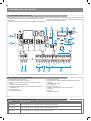
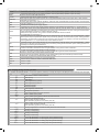
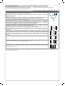
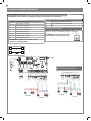
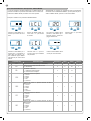
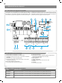
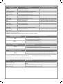
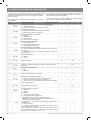
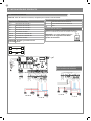
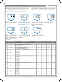
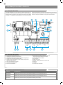
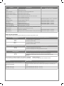
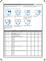
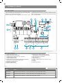
2.1 - Description of the control unit
The CBX20224 control unit is the most modern, ecient system for
the control of Marantec motors for the electric opening and closure of
swing gates.
All other, improper, use of the control unit is forbidden. The CBX20224
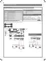
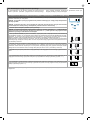
2.2 - Description of the connections
1- Motor power supply connections
2- Transformer power supply connections
3- 24Vdc and 24Vac output connections to controls and safety
devices
4- Connector for battery charger KBP
5- Connection of ashing light, courtesy light, gate open indicator
light/electric lock
6- Functions display
7- Safety device dip switch
8- Fuse 2AT slow-acting
9- STOP-PH2-PH1-OPEN-CLOSE-PAR-SBS safety led and led
input led
10- STEPPING SBS button
11- UP + button up
12- MENU button menu
13- DOWN - (DOWN) button down and radio menu
14- Antenna
15- KEY led
16- Encoder connections
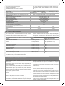
2.3 - Models and technical characteristics
has a display allowing easy programming and constant monitoring
of the input status; the menu structure also allows easy setting of
working times and operating modes.
2 - INTRODUCING THE PRODUCT
24 VAC
24 VAC
M1+
M1-
M2+
M2-
COM
FLASH
IND ELEC
LED
v+
ENC M1
ENC M2
NEG
NEG
PH POW
STOP
STOP
PH2
PH1
OPEN
CLOSE
SBS
PED
COM
SHIELD
ANT
POWER
SUPPLY
UP
+ -
MENU
SBS
DOWN
(RADIO)
BATTERIES
1 13
2
4
5 3
68 7 15
9
10
12
13
11
14
16
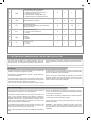
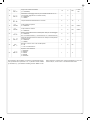
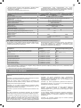
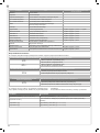
CODE DESCRIPTION
CBX20224H 24V control unit for two swing gate motors in box (trasformer 250 VA)
CBX20224L 24V control unit for two swing gate motors in box (trasformer 150 VA)
CBX20224 24V control unit for two swing gate motors (control unit only)

5
EN
3 - PRELIMINARY CHECKS
Before installing the product, perform the following checks and in-
spections:
check that the gate, the door or the barrier is suitable for automation;
the weight and size of the gate or door and the balance of the barrier
boom must be within the operating limits specied for the automa-
tion system in which the product is installed;
heck that the gate or door has rm, eective mechanical safety
stops;
make sure that the product xing zone is not subject to ooding;
high acidity or salinity or nearby heat sources might cause the pro-
duct to malfunction;
in case of extreme weather conditions (e.g. snow, ice, wide tempe-
rature variations or high temperatures), friction may increase, cau-
sing a corresponding rise in the force needed to operate the system;
the starting torque may therefore exceed that required in normal
conditions;
check that when operated by hand the gate, the door or the barrier
moves smoothly without any areas of greater friction or derailment
risk;
check that the gate, door or the barrier is well balanced and will the-
refore remain stationery when released in any position;
check that the electricity supply line to which the product is to be
connected is suitably earthed and protected by an overload and dif-
ferential safety breaker device;
he system power supply line must include a circuit breaker device
with a contact gap allowing complete disconnection in the condi-
tions specied by class III overvoltage;
ensure that all the material used for installation complies with the
relevant regulatory standards.
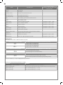
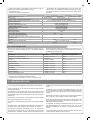
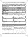
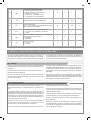
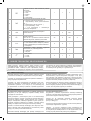
2.4 - List of cables required
The cables required for connection of the various devices in a stan-
dard system are listed in the cables list table.
The cables used must be suitable for the type of installation; for
example, an H03VV-F type cable is recommended for indoor appli-
cations, while H07RN-F is suitable for outdoor applications.
* If the power supply cable is more than 20 m long, it must be of larger gauge (3x2.5mm
2
) and a safety grounding system must be installed
near the automation unit
** Two cables of 2 x 0.5 mm
2
can be used as an alternative
ELECTRIC CABLE TECHNICAL SPECIFICATIONS
Connection cable maximum allowable limit
Control unit power supply line 1 x cable 3 x 1,5 mm
2
20 m *
Flashing light, courtesy light
Antenna
3 x 0,5 mm
2
**
1 x cable type RG58
20 m
20 m (advised < 5 m)
Electric lock 1 x cable 2 x 1 mm
2
10 m
Transmitter photocells 1 x cable 2 x 0,5 mm
2
20 m
Receiver photocells 1 x cable 4 x 0,5 mm
2
20 m
Sensitive edge 1 x cable 2 x 0,5 mm
2
20 m
Key-switch 1 x cable 4 x 0,5 mm
2
** 20 m
Motor power supply line 1 x cable 2 x 1,5 mm
2
10 m
Encoder power supply line 1 x cable 3 x 0,5 mm
2
10 m
- Power supply with protection against short-circuits inside the con-
trol unit, on motors and on the connected accessories;
- Obstacle detection;
- Automatic learning of working times;
- Safety device deactivation by means of dip switches: there is no
need to bridge the terminals of safety devices which are not instal-
led - the function is simply disabled by means of a dip switch.
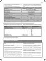
TECHNICAL SPECIFICATIONS CBX20224H CBX20224L CBX20224
Power supply (L-N) 230Vac (+10% - 15%) 50/60 Hz 24 Vdc (+10% - 15%)
Rated power maximum 280W maximum 210W -
Photocell power supply output 24Vdc (without regulation) maximum 250mA
Output for Vac accessories power/device test power Vdc 24 Vac without regulation 200 mA / 24 Vdc without regulation 250 mA
Flashing light output 24Vdc (without regulation) 15W
Courtesy light output 24Vdc (without regulation) 15W
Electric lock output 12Vac 15VA maximum
Gate open warning light output 24Vdc (without regulation) 5W
Antenna input 50Ω type cable RG58
Operating temperature -20°C + 55°C
Accessory fuses 2AT
Power supply line fuses 1.6AT -
Max. number of transmitters storage
Compatible with all Marantec “Bi-Linked” transmitters
200
Use in particularly acid, saline or explosive atmospheres NO
Protection class IP54 IPXX
Control unit dimensions 222 x 110 x 275 H mm
Weight 3,93 kg 245 g

6
EN
4 - PRODUCT INSTALLATION
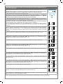
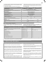
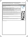
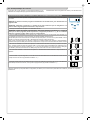
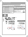
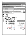
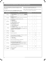
4.1 - Electrical connections
WARNING - Before making the connections, ensure that the control unit is not powered up.
ON
1 2 3
STOP
PH2
PH1
MOTOR CONNECTION
Power supply connection terminal board
M + Power supply of motor M1 +
M - Power supply of motor M1 -
M2 + Power supply of motor M2 +
M2 - Power supply of motor M2 -
V+ Power supply of Encoder +
ENC M1 Encoder connections M1
ENC M2 Encoder connections M2
NEG Power supply of Encoder -
POWER SUPPLY CONNECTOR
L Power supply live 230 Vac 50-60 Hz
N Power supply neutral 230 Vac 50-60 Hz
Earth
DIP SWITCH
Set on “ON” to disable inputs STOP, PH1, PH2
Eliminates the need to bridge the terminal board inputs.
WARNING - with the dip switch ON,
the safety devices are disabled
PHOTOTEST
OUTPUT LED
OPEN
PHOTOCELL 1
PHOTOCELL 2
CLOSE
PEDESTRIAN
STEP BY STEP
COMMON
STOP/EDGE
INDICATOR
NEGATIVE
24 VAC
24 VAC
M1 M2
2
3
4
1
1
2
TX
RX
NC
PH2
2
3
4
1
1
2
TX
RX
PH1
GND
_
12/24
AC/DC
GND
_
12/24
AC/DC
COM
OUT
GND
_
12/24
AC/DC
GND
_
12/24
AC/DC
COM
OUT
NC
N
T1,6A
L
230Vac
50/60Hz
COMMON
FLASH
24 VAC
24 VAC
M1+
M1-
M2+
M2-
COM
FLASH
IND ELEC
LED
v+
ENC M1
ENC M2
NEG
+ ALIM. ENCODER
- ALIM. ENCODER
ENCODER 1
ENCODER 2
NEG
PH POW
STOP
STOP
PH2
PH1
OPEN
CLOSE
SBS
PED
COM
SHIELD
ANT
POWER
SUPPLY
UP
+ -
MENU
SBS
DOWN
(RADIO)
COM
LED
FLASH
2
3
4
1
1
2
TX
RX
NC
PH2
2
3
4
1
1
2
TX
RX
PH1
GND
_
12/24
AC/DC
GND
_
12/24
AC/DC
COM
OUT
GND
_
12/24
AC/DC
GND
_
12/24
AC/DC
COM
OUT
NC
PHOTOTEST
OUTPUT LED
OPEN
PHOTOCELL 1
PHOTOCELL 2
CLOSE
PEDESTRIAN
STEP BY STEP
COMMON
STOP/EDGE
INDICATOR
NEGATIVE
24 VAC
24 VAC
M1
M2
COMMON
FLASH
24 VAC
24 VAC
M1+
M1-
M2+
M2-
COM
FLASH
IND ELEC
LED
v+
ENC M1
ENC M2
NEG
+ ALIM. ENCODER
- ALIM. ENCODER
ENCODER 1
ENCODER 2
NEG
PH POW
STOP
STOP
PH2
PH1
OPEN
CLOSE
SBS
PED
COM
UP
+ -
MENU
SBS
DOWN
(RADIO)
N
T1,6A
L
230Vac
50/60Hz
SHIELD
ANT
POWER
SUPPLY
ELECTRICAL CONNECTIONS
FOR ENERGY SAVING
M1M2
M2M1
WARNING - The motor and the encoder must
not be connected together

7
EN
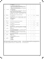
SAFETY AND CONTROL DEVICE CONNECTORS
24 VAC Accessories power supply 24 Vac without regulation, 200 mA (with battery operation output not active)
24 VAC Accessories power supply 24 Vac without regulation, 200 mA (with battery operation output not active)
COM Common for the FLASH-IND-LED outputs
FLASH Flashing light output 24Vdc (without regulation), maximum 15W
IND/ELEC
IND output for gate open indicator light 24 Vdc not regulated 5W MAX / Electric lock output 12Vac, 15VA maximum
selectable with parameter IN.D.
LED
Courtesy light output 24Vdc (without regulation), maximum 15W, controllable also via radio ON-OFF command (radio
channel 4 selecting fC.y. = 2, tC.y. = 0 )
NEG Photocell and encoder power supply negative
PH-POW
Photocells PH1 and PH2 power supply positive; phototest can be selected with parameter tp.h. 24 Vdc, 250 mA
STOP
STOP safety device, NC contact between STOP and STOP (warning, with dip switch 1 ON the safety device input is
o). This input is classied as a safety device; the contact can be deactivated at any time, cutting out the automation
system and disabling all functions, including Automatic Closure.
Safety sensor edge, ON/OFF, NC contact or resistive 8K2 between STOP and STOP.
Input selectable with parameter Ed.m.
PH2
Photocells (opening), NC contact between PH2 and COM (warning, with dip switch 2 ON the PHOTOCELL 2 safety
device input is o). The photocell is tripped at any time during opening of the automation system, halting operation
immediately; the automation system will continue opening when the contact is restored. In the event of intervention on
closure (parameter Ph.2. = 0) the device stops and on release re-opens
PH1
Photocells (closing), NC contact between PH1 and COM (warning, with dip switch 3 ON the PHOTOCELL 1 safety
device input is o) The photocell is tripped at any time during closing of the automation system, halting operation im-
mediately and reversing the travel direction
OPEN
OPEN command NO contact between OPEN and COM
Contact for the HOLD-TO-RUN function. The gate OPENS as long as the contact is held down
CLOSE
CLOSE command NO contact between CLOSE and COM
Contact for the HOLD-TO-RUN function. The gate CLOSES as long as the contact is held down
PAR
PARTIAL command NO contact between PAR and COM
Used to open the gate partially, depending on the software setting (not active in barrier/up-and-over mode)
SBS
STEPPING command NO contact between SBS and COM
Open/Stop/Close/Stop command, or as set in the software
COM Common for the PH2-PH1-OPEN-CLOSE-PAR-SBS inputs
SHIELD Antenna - shield -
ANT Antenna - signal -
4.2 - Display during normal operation
In “NORMAL OPERATING MODE”, i.e. when the system is powered up normally, the 3-gure LCD display shows the following status messages:
MESSAGES MEANING
--
Gate closed or switch-on after shutdown
OP
Gate opening
CL
Gate closing
SO
Gate stopped during opening
SC
Gate stopped during closure
F1
Photocell 1 tripped
F2
Photocell 2 tripped
HA
Gate stopped by external event
ALI
Re-alignment procedure
oP
Gate stopped without automatic reclosure
OPD
Gate in partial opening mode
Pe
Gate in partial opening position without automatic reclosure
-tC
Gate open with timed reclosure
Flashing dash counting in progress
Dash replaced by gures 0..9 countdown (last 10s)
-tP
Gate in partial opening position with timed reclosure
Flashing dash counting in progress
Dash replaced by gures 0..9 countdown (last 10s)
L--
Learning stopped due to activation of safety device or motor inversion
LOP
Learning on M1 opening
LO.P.
Learning on M2 opening
LCL
Learning on M1 closing
LC.L.
Learning on M2 closing
SOP
Point of M1 deceleration on opening (only during stroke learning)
SO.P.
Point of M2 deceleration on opening (only during stroke learning)
SCL
Point of M1 deceleration on closing (only during stroke learning)
SC.L.
Point of M2 deceleration on closing (only during stroke learning)
n

8
EN
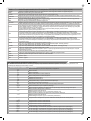
Malfunctions
This section lists a number of malfunctions which may occur.
After eliminating the cause of the alarm, to delete all errors simply
press the “DOWN” key or press the SBS (STEPPING) command
The display returns to the normal screen.
PHOTOCELL ALARM/SAFETY EDGE Phototest fail outcome
EPH
1. Check the photocell and the safety edge connections
2. Check that the photocells and the safety edg are operating correctly
EVENT DESCRIPTION
KEY TO MAIN CONTROL
FLASHING LIGHT AND KEY LEDS
CONTROL UNIT
opening Gate opening
closure Gate closing
automatic closure Gate open with timed reclosure active
stop during closure Gate stopped during closure
stop during opening Gate stopped during opening
open Gate completely open without automatic reclosure
closed Gate completely closed
programmation During the programming phase 2 quick ashes + pause + 1 ash
obstacle M1/M2 Motor 1/2 obstacle detected 4 quick ashes + pause, 3 times
photo 1! Photocell 1 tripped 2 quick ashes + pause, 3 times
photo 2! Photocell 2 tripped 2 quick ashes + pause, 3 times
sensitive edge! Sensitive edge tripped 5 quick ashes + pause, 3 times
partial opening Partial opening in progress
automatic partial closure Gate opening to partial position with timed reclosure activated
realignment Realignment after a manual release
phototest error Phototest error detected 3 quick ashes + pause, 3 times
IND/ELEC error Electric lock / gate open light line overload 6 quick ashes + pause, 3 times
DISPLAY MEANING
Status display (--, OP, CL, SO, ecc..) Description of the control unit (--, OP, CL, SO, ecc..)
Maneuvers performed Counter displays alternating the thousands (without dots) and the units (with dots)
Motor current 1 [A] Motor current absorption (e.g. 1.5=1.5A)
Motor current 2 [A] Motor current absorption (e.g. 1.5=1.5A)
Press “UP“ to read the following parameters on display.
SURGE OVERLOAD ALARM The motor’s current drawdown has increased very quickly
EOL
1. The gate has hit an obstacle (M1)
2. There is friction on the leaf of M1
EO.L.
1. The gate has hit an obstacle (M2)
2. There is friction on the leaf of M2
SAFETY EDGE ALARM The control unit has received a signal from the safety edge
EED
1. The safety edge has been pressed.
2. The safety edge is not connected correctly

9
EN
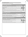
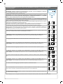
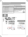
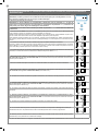
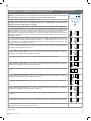
4.3 - Autolearning of the travel stroke
The rst time the control unit is powered up, an autolearning proce-
dure must be carried out to acquire fundamental parameters such
as the travel stroke length and deceleration points.
All the main parameters are set with the default settings by the control unit. To customise the installation, proceed as described in point 4.6
below.
AUTOLEARNING OF THE TRAVEL STROKE AND MAIN PARAMETERS
The decelerations will be those set in the menu, with the same percentage during both opening and closing.
CAUTION: if manual programming of deceleration intervals is required, go to the next table
CAUTION! check that mechanical end stops (compulsory) are present and secure. The motors must
always reach the mechanical end stop
1. Move the gate manually to mid-travel
CAUTION: 2. Before proceeding with programming, use parameter de.f. to select the type of motor to
be programmed (see paragraph 6, conguration of parameter de.f.). If this phase is not completed, this
may cause serious damage to the automation!
3. Press the pushbuttons UP and MENU at the same time for at least 5 seconds until LOP is displayed, then (if
necessary) press DOWN (see gure).
Ensure that motor M1 is activated rst; otherwise, press DOWN, turn the power o and invert connections M1
and M2. Repeat the procedure from step 3.
If the rst manoeuvre is NOT opening, press DOWN to stop the self-learning process. Then press SBS to re-
start acquisition: the leaf resumes movement in the correct direction
4. Motor M1 opens at low speed until it reaches the mechanical opening end stop.
On reaching the mechanical end stop on opening of M1 motor M2 starts automatically in opening mode (the
display shows LO.P.). If motor M2 moves in closing, stop by pressing DOWN and resume movement using SBS
(the leaf resumes movement in the correct direction)
5. The motor M2 opens at low speed until reaching the mechanical opening end stop.
6. After a couple of seconds, motor M2 starts up automatically at low speed until reaching the mechanical clo-
sing end stop (the display shows LC.L.)
7. On reaching the mechanical opening end stop of M2, motor M1 closes at low speed until reaching the me-
chanical closing end stop, thus completing the programming phase (the display shows LCL)
UP
+
SBS
DOWN
-
MENU
5
M1 M2
6
M1
M2
7
M2M1
M1
M2
3
SBS
M1
M2
4
SBS

10
EN
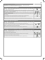
AUTOLEARNING OF THE TRAVEL STROKE AND MAIN PARAMETERS, WITH CUSTOMISED
DECELERATIONS
Deceleration intervals can be personalised by the user, according to the procedure below
CAUTION! check that mechanical end stops (compulsory) are present and secure. The motors must
always reach the mechanical end stop
1. Move the gate manually to mid-travel
CAUTION: 2. Before proceeding with programming, use parameter de.f. to select the type of motor to
be programmed (see paragraph 6, conguration of parameter de.f.). If this phase is not completed, this
may cause serious damage to the automation!
3. CAUTION: enter the main menu to set the parameter LSI = pas per the table in paragraph 4.6
4. Press the pushbuttons UP and MENU at the same time for at least 5 seconds until LOP is displayed, then (if
necessary) press DOWN (see gure).
Ensure that motor M1 opens rst; otherwise, press DOWN, turn the power o and invert connections M1 and
M2. Repeat the procedure from step 4.
If the rst manoeuvre is NOT opening, press DOWN to stop the self-learning process. Then press SBS to restart
acquisition: the leaf resumes movement in the correct direction
5. Motor M1 opens at low speed until it reaches the mechanical opening end stop.
On reaching the mechanical end stop on opening of M1 motor M2 starts automatically in opening mode (the
display shows LO.P.). If motor M2 moves in closing, stop by pressing DOWN and resume movement using SBS
(the leaf resumes movement in the correct direction)
6. The motor M2 opens at low speed until reaching the mechanical opening end stop. After a couple of seconds,
the motor M2 closes at low speed (the display shows LC.L.)
7. On reaching the point where motor M2 closing deceleration is required, press SBS. M2 motor move-
ment continues at low speed (the display shows SC.L.)
8. On reaching the mechanical end stop of motor M2, motor M1 starts closing
9. On reaching the point where motor M1 closing deceleration is required, press SBS. M1 motor move-
ment continues at low speed (the display shows SCL)
10. When motor M1 reaches the closed position, motor M1 stops and restarts in opening
11. On reaching the point where motor M1 opening deceleration is required, press SBS. M1 motor move-
ment continues at low speed (the display shows SOP)
12. When motor M1 reaches the open position, motor M1 stops and motor M2 starts in opening
13. On reaching the point where motor M2 opening deceleration is required, press SBS. M2 motor move-
ment continues at low speed. (the display shows SO.P.)
14. When motor M2 reaches the open position, motor M2 stops
15. M1 and M2 resume closing according to the oset parameter entered in the menu, i.e. the gate closes au-
tomatically according to the set travel
16. Run a number of opening, closing and stop manoeuvres, to check that the system is stable and there are
no assembly defects.
15
M1 M2
8
M1
M2
10
M2M1
12
M1
M2
14
M1 M2
M1
M2
4
SBS
M1
M2
5
SBS
6
M1 M2
7M1
M2
SBS
9
M1
M2
SBS
11
M1
M2
SBS
13
M1
M2
SBS
+
SBS
-
MENU
The deceleration points not assigned manually will be automatically set at 20% of the control unit stroke

11
EN
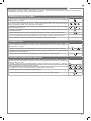
4.4 - Learning a transmitter
A transmitter can be “learned” via the specic programming menu or
by remote memorisation, using a previously memorised transmitter.
CLEARING THE ENTIRE RECEIVER MEMORY
If you are in programming mode exit pressing the MENU button until -- appears. Press the DOWN (RADIO)
button for more than 2 seconds. Until the display shows the word “rd” (radio), then release the button
1. Press the DOWN (RADIO) button and hold it down until the LED lights up (about 3 seconds) and then goes
out (about 3 seconds). Release the key.
(>3s)-> (>3s)->
2. About 1 second after the key is released, the KEY LED starts to ash
(1s)+ (1s)+
3. Press the key on the receiver as the LED ashes for the third time
4. If the deletion has been successful, the KEY LED will give one long ash
3s
MEMORISING A REMOTE CONTROL
If you are in programming mode exit pressing the MENU button until -- appears. Press the DOWN (RADIO)
button for more than 2 seconds. Until the display shows the word “rd” (radio), then release the button
1. Press and release the DOWN (RADIO) button a number of times equal to the number of the function to be
selected: once for function STEP BY STEP, twice for function PARTIAL, three times for function ONLY OPEN,
four times for function LIGHT ON/OFF
+ +
2. The KEY LED will ash a number of times equal to the number of the function selected, with 1 second pauses
between ashes
+1s +1s
3. Press the back key of the remote control to be memorized and then press the front key within 7 seconds
2s
4. If the memorization has been successful, the KEY LED will give one long ash
3s
5. To memorize another remote control on the same function, repeat point 3
N.B If no commands are given for 7 seconds, the receiver automatically quits the programming mode
DELETING A REMOTE CONTROL
If you are in programming mode exit pressing the MENU button until -- appears. Press the DOWN (RADIO)
button for more than 2 seconds. Until the display shows the word “rd” (radio), then release the button
1. Press the DOWN (RADIO) button until the LED lights up (about 3 seconds), then release the button
(>3s)->
2. Press the key of the remote control to be deleted within 7 seconds
3. If the deletion has been successful, KEY LED will give one long ash
3s

12
EN
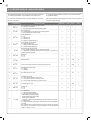
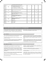
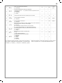
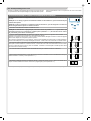
PARAMETERS DESCRIPTION DEFAULT MIN MAX UNIT
1
TCL
Automatic reclosure time (0 = o) 0 0 900 s
2
ttr
Reclosing time after transit on PH1
(0 = o)
0 0 30 s
3
SEI
Sensitivity on obstacles
0 = Maximum impact force
10 = Minimum impact force
3 0 10
4
SFO
Motor speed during opening
1 = minimum
2 = low
3 = medium
4 = high
5 = maximum
4 1 5
5
SSO
Motor speed during opening deceleration phase
1 = minimum
2 = low
3 = medium
4 = high
5 = maximum
1 1 5
6
SFC
Motor speed during closing
1 = minimum
2 = low
3 = medium
4 = high
5 = maximum
4 1 5
7
SSC
Motor speed during closing deceleration phase
1 = minimum
2 = low
3 = medium
4 = high
5 = maximum
1 1 5
4.5 - Customising the system - BASIC MENU
If necessary, users may select a BASIC MENU which allows modi-
cation of the control unit’s basic parameters. To select the BASIC
MENU proceed as described below.
WARNING: to be certain of accessing the NORMAL OPERATION
display state, the starting point for accessing the BASIC MENU,
press the MENU key twice
Exampling of modifying a BASIC MENU parameter
After accessing the BASIC
MENU, press the + and – keys
to scroll through the functions.
Press the MENU key quickly to
quit the menu.
Press the MENU key for 1 se-
cond to access the basic menu.
Press the + and – keys to scroll
through the functions to modify
other parameters.
Press the + and – keys to to
modify the value.
Press the MENU key for 1 se-
cond to display the parameter
in order to save the modied
value, or MENU quickly to quit
the function without saving.
To access the value modica-
tion function, press the MENU
key for 1 second, until the va-
lue starts to ash quickly.
UP
+
+ + +
+ + +
DOWN
-
- - -
- - -
MENU
UP
DOWN
MENU
UP
DOWN
MENU
UP
DOWN
MENU
UP
DOWN
MENU
UP
DOWN
MENU
UP
DOWN
MENU

13
EN
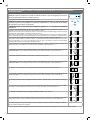
13
8
SBS
STEP BY STEP or SBS conguration:
0 = Normal (AP-ST-CH-ST-AP-ST…)
1 = Alternate STOP (AP-ST-CH-AP-ST-CH…)
2 = Alternate (AP-CH-AP-CH…)
3 = Apartment block – timer (N.B TCL ≠ 0)
4 = Apartment block with immediate reclosure
0 0 4
9
DLY
Second leaf delay on opening 2 0 300
10
LSI
Deceleration distance
0 to 100 = Motor deceleration percentage during
opening and closure
20 0 100 %
11
BlT
Post blackout procedure
0 = No action, remains stationery
1 = Closure
0 0 1
12
SBY
Energy saving: enables photocell switch-o when gate
is closed
0= disabled
1= enabled
0 0 1
13
nMt
Number of motors
1 = 1 motor
2 = 2 motors
2 1 2
n
5.2 Commissioning
Once all (and not just some) of the system devices have passed the
testing procedure, the system can be commissioned;
the system’s technical dossier must be produced and kept for 10
years. It must contain the electrical wiring diagram, a drawing or
photograph of the system, the analysis of the risks and the solutions
adopted to deal with them, the manufacturer’s declaration of con-
formity for all connected devices, the operator’s manual for every
device and the system maintenance plan;
x a dataplate with the details of the automation, the name of the
person who commissioned it, the serial number and year of con-
struction and the CE marking on the gate or door;
also t a sign specifying the procedure for releasing the system by
hand;
draw up the declaration of conformity, the instructions and precau-
tions for use for the end user and the system maintenance plan and
consign them to the end user;
ensure that the user has fully understood how to operate the system
in automatic, manual and emergency modes;
the end user must also be informed in writing about any risks and
hazards still present;
WARNING - after detecting an obstacle, the gate or door stops
during its opening travel and automatic closure is disabled; to re-
start operation, the user must press the control button or use the
transmitter.
5 - TESTING AND COMMISSIONING THE AUTOMATION SYSTEM
5.1 Testing
All system components must be tested following the procedures de-
scribed in their respective operator’s manuals;
ensure that the recommendations in Chapter 1 - Safety Warnings -
have been complied with;
check that the gate or door is able to move freely once the automa-
tion system has been released and is well balanced, meaning that it
will remain stationery when released in any position;
check that all connected devices (photocells, sensitive edges,
emergency buttons, etc.) are operating correctly by performing gate
or door opening, closing and stop tests using the connected control
devices (transmitters, buttons or switches);
perform the impact measurements as required by the EN12453
standard, adjusting the control unit’s speed, motor force and de-
celeration functions if the measurements do not give the required
results, until the correct setting is obtained.
The system must be tested by a qualied technician, who must
perform the tests required by the relevant standards in relation to
the risks present, to check that the installation complies with the
relevant regulatory requirements, especially the EN12453 standard
which species the test methods for gate and door automation sy-
stems.

14
EN
6 - FURTHER DETAILS - ADVANCED MENU
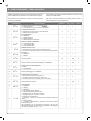
PARAMETS DESCRIPTION DEFAULT MIN MAX UNIT
1
SP.h.
Use of PHOTO1 when starting from closed
0 = PHOTO1 is checked
1 = The gate starts even with PHOTO1 excited
1 0 1
2
Ph.2.
Use of PHOTO2
0 = Enabled during both opening and closing AP/CH
1 =Only enabled during opening AP
0 0 1
3
tP.h.
Photo-device test
0 = o
1 = PHOTO1 on
2 = PHOTO2 on
3 = PHOTO1 and PHOTO2 on
0 0 3
4
Ed.m.
STOP/EDGE input selection
0 = STOP contact (NC)
1 = Resistive safety edge (8k2)
2 = Contact safety edge (NC)
0 0 2
5
iE.D.
Sensitive edge tripping mode
0= only tripped during closure with direction reversal
1 = stops the automation (during both opening and closure) and
retreats from the obstacle
0 0 1
6
tE.D.
Edge test
0 = o
1 = on
0 0 1
7
LP.o.
Partial opening 50 0 100 %
8
TP.C.
Time for automatic closure from partial opening (0=o) 0 0 900 s
9
FP.r.
Flashing light output setup
0 = Steady
1 = Flashing
1 0 1
10
tP.r.
Pre-ashing time (0 = o) 0 0 20 s
11
FC.Y.
Courtesy light setup
0 = On at end of operation for time TCY
1 = On if gate not closed + duration of TCY
2 = On if courtesy light timer (TCY) time not out
0 0 2
12
tC.Y.
Courtesy light on time 0 0 900 s
13
de.a.
Hold-to-run
0 = o
1 = on
0 0 1
14
IN.D.
0 = deactivated
1 = gate open light ON/OFF
2 = gate open light proportional
- Slow ashing with gate opening
- Quick ashing with gate closing
- Steady light if gate open
- 2 ashes + pause with gate stationary (position other than closed)
3 = Electric lock
4 = Magnetic electric lock function with output active when gate/door
is closed
N.B. interface with an external relay with 24 Vdc winding. To activate
this function, the pre-ash must be enabled at the recommended
value of 1 sec (tP.r. ≠ 0)
0 0 4
The ADVANCED MENU allows the system to be further customised
by modifying parameters not accessible from the basic menu.
To access the ADVANCED menu, press the MENU key and hold it
down for 5 seconds.
To modify ADVANCED MENU parameters, proceed as described
for the BASIC MENU.
N.B. Some default functions/display items may vary with respect to
the type of motor selected.
n

15
EN
15
se.r.
Service interval cycle threshold
(0 = o)
10 0 200
x 1000
cycles
16
se.f.
Enabling of continuous ashing indicating service required with se.r.
≠ 0 (only active with gate closed)
0 = o
1 = on
0 0 1
17
EL.T.
Electric lock activation time in seconds 2 1 10 s
18
HA.o.
Water hammer on opening
0 = disabled
0 0 100 *100ms
19
HA.c.
Water hammer on closing
0 = disabled
0 0 100 *100ms
20
rE.L.
Motor release from closed/open limit switch. Useful for lightweight
gates
0 = o
1 to 10 release levels (1 = minimum release, 10 = maximum release)
0 0 10
21
ST.P.
High-speed motor start-up
0 = on
1 = o
0 0 1
22
dm.I.
Leaf 1 closing delay with gate open
0 = O
1 = 1 to 20 Seconds On
1 0 20
23
DE.F.
Reset to default values
1= RA2224E
2= RE2224
3= UN24E
4= ST3024
5= RA4224E
1 1 4
n
To set the default values: 1) access the advanced programming fun-
ction; 2) select the “dEf” parameter”; 3) activate the modication
mode (“0” on display”); 4) accept the modication (press “MENU”
and hold it down). A countdown should now appear: 49,48...,1
down to “don“. Release the key when nished.

16
EN
Marantec Antriebs- und Steuerungstechnik GmbH & Co. KG produ-
ces systems for the automation of gates, garage doors, automatic
doors, roller blinds and car-park and road barriers. However, Ma-
rantec is not the manufacturer of your complete automation system,
which is the outcome of the analysis, assessment, choice of mate-
rials and installation work of your chosen installer. Every automation
system is unique, and only your installer has the experience and
skill required to produce a safe, reliable, durable system tailored to
your needs, and above all that complies with the relevant regulatory
standards. Although your automation system complies with the re-
gulation safety level, this does not rule out the presence of “residual
risk”, meaning the possibility that hazards may occur, usually due to
reckless or even incorrect use. We would therefore like to give you
some advice for the correct use of the system:
• before using the automation system for the rst time, have the
installer explain the potential causes of residual risks to you;
• keep the manual for future reference, and pass it on to any new
owner of the automation system;
• reckless use and misuse of the automation system may make it
dangerous: do not operate the automation system with people, ani-
mal or objects within its range of action;
• a properly designed automation system has a high level of safety,
since its sensor systems prevent it from moving with people or ob-
stacles present so that its operation is always predictable and safe.
However, as a precaution children should not be allowed to play clo-
se to the automation system, and to prevent involuntary activation,
remote controls must not be left within their reach;
• as soon as any system malfunction is noticed, disconnect the
electricity supply and perform the manual release procedure. Never
attempt repairs on your own; call in your installation engineer. In
the meantime the door or gate can be operated without automation
once the geared motor has been released using the release key
supplied with the system. In the event of safety devices out of ser-
vice arrange for repairs to the automation immediately;
• in the event of malfunctions or power failures: while waiting for the
engineer to come (or for the power to be restored if your system is
not equipped with buer batteries), the door or gate can be used just
like any non-automated installation. To do this, the manual release
procedure must be carried out;
• manual release and operation: rst bear in mind that the release
procedure can only be carried out with the door or gate stationery.
• Maintenance: Like any machine, your automation system needs
regular periodic maintenance to ensure its long life and total safety.
Arrange a periodic maintenance schedule with your installation en-
gineer. Marantec recommends that maintenance checks should be
carried out every six months for normal domestic use, but this inter-
val may vary depending on the level of use. Any inspection, main-
tenance or repair work must only be carried out by qualied sta.
• Never modify the automation system or its programming and setup
parameters: this is the responsibility of your installation engineer.
• Testing, routine maintenance and any repairs must be recorded by
the person who performs them and the documents must be conser-
ved by the system’s owner.
The only procedures you are capable of, and which you are recom-
mended to perform, are cleaning of the photocell glass and removal
of any leaves or stones that may obstruct the automation system.
To prevent anyone from activating the gate or door, release the au-
tomation system before starting. Clean only with a cloth dipped in
a little water.
At the end of its useful life, the automation system must be disman-
tled by qualied personnel, and the materials must be recycled or
disposed of in compliance with the legislation locally in force.
If after some time your remote control seems to have become less
eective, or stops operating completely, the battery may be at (de-
pending on the level of use, this may take from several months up
to more than a year). You will realise this because the transmission
conrmation light does not come on, or only lights up for a very
short time.
Batteries contain pollutants: do not dispose of them with normal wa-
ste but follow the methods specied by the local regulations.
Thank you for choosing Marantec Antriebs- und Steuerungstechnik
GmbH & Co. KG; please visit our Internet site www.marantec.com
for further information.
7 - INSTRUCTIONS AND WARNINGS FOR THE END USER

17
EN
NOTES

18
DE
1
2
3
4
5
6
7
8
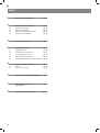
Sicherheitshinweise
2.1
2.2
2.3
2.4
4.1
4.2
4.3
4.4
4.5
5.1
5.2
Einführung in das Produkt
Beschreibung des Steuergerätes
Beschreibung der Anschlüsse
Modelle und technische Eigenschaften
Liste benötigter Kabel
Vorabkontrollen
Produktinstallation
Elektrische Anschlüsse
Anzeige Normalmodus
Einlernen des Laufs
Lernfunktion eines Senders
Benutzerdenierte Einrichtung der Anlage -
GRUNDMENÜ
Test und Inbetriebnahme
Abnahme
Inbetriebnahme
Vertiefung - ERWEITERTES MENÜ
Anweisungen und Hinweise für
den Endbenutzer
EG-Konformitätserklärung
S. 19
S. 20
S. 20
S. 20
S. 20
S. 21
S. 21
S. 22
S. 22
S. 23
S. 25
S. 27
S. 28
S. 29
S. 29
S. 29
S. 30
S. 32
S. 115
INHALTSVERZEICHNIS

19
DE
1 - SICHERHEITSHINWEISE
ORIGINALANWEISUNGEN – Wichtige Sicherheitsanweisun-
gen. Für die Sicherheit der Personen ist es wichtig, die folgen-
den Sicherheitsanweisungen zu befolgen. Bewahren Sie diese
Anweisungen auf.
Vor Durchführung der Installation lesen Sie die Anleitung bitte
aufmerksam durch.
Die Konstruktion und die Herstellung der Geräte, aus denen
sich das Produkt zusammensetzt, und die in diesem Handbuch
enthaltenen Informationen entsprechen den geltenden Si-
cherheitsvorschriften. Dennoch können eine falsche Installa-
tion und eine falsche Programmierung schwerwiegende Ver-
letzungen bei Personen verursachen, die die Arbeit ausführen,
und bei denen, die die Anlage benutzen werden. Aus diesem
Grund ist es wichtig, während der Installation strikt alle Anwei-
sungen in diesem Handbuch zu beachten.
Bei Zweifel jeglicher Art die Installation abbrechen und ggf. den Ma-
rantec Kundendienst zur Klärung kontaktieren.
Für die europäische Gesetzgebung muss der Einbau einer au-
tomatischen Tür oder eines automatischen Tors den Bestim-
mungen der Richtlinie 2006/42/EG (Maschinenrichtlinie) und im
Besonderen den Normen EN 12453, EN 12635 und EN 13241-1
entsprechen, die eine Konformitätserklärung der Automatisie-
rung ermöglichen.
In Anbetracht dessen müssen die endgültige Verbindung der Auto-
matisierung ans Stromnetz, die Endabnahme der Anlage, die Inbe-
triebnahme und die regelmäßige Wartung von qualiziertem und
erfahrenem Personal entsprechend den Anleitungen unter „Prüfung
und Inbetriebnahme der Automatisierung“ durchgeführt werden.
Außerdem muss das Personal auch die vorgesehenen Tests nach
den vorhandenen Risiken festlegen und die Einhaltung der Ge-
setze, Vorschriften und Regeln überprüfen: insbesondere die Ein-
haltung der Norm EN12453, welche die Prüfverfahren für die Auto-
matisierung von Türen und Toren festlegt.
Vor Installationsbeginn folgende Analysen und Prüfungen dur-
chführen:
Sicherstellen, dass die für die Automatisierung vorgesehenen
Vorrichtungen für die zu realisierende Anlage geeignet sind. Die-
sbezüglich aufmerksam die im Kapitel „Technische Eigenschaften“
aufgeführten Daten prüfen. Die Installation nicht durchführen, wenn
auch nur eine der Vorrichtungen nicht für den Gebrauch geeignet
ist.
Sicherstellen, dass die erworbenen Vorrichtungen ausreichend
sind, um die Sicherheit und Funktion der Anlage zu gewährleisten.
Die Risikoanalyse durchführen, welche auch die Liste der Si-
cherheitsanforderungen, aufgeführt in Anhang I der Maschinenricht-
linie, beinhalten muss, und die angewandten Lösungen nennen.Die
Risikoanalyse ist eine der Unterlagen, aus denen sich die techni-
schen Unterlagen der Automatisierung zusammensetzen. Diese
müssen von einem erfahrenen Installateur ausgefüllt werden.
In Anbetracht der Gefahrensituationen, die bei Installation und
Benutzung des Produktes auftreten können, muss die Automa-
tisierung unter Berücksichtigung folgender Hinweise installiert
werden:
Keine Änderungen an der Automatisierung vornehmen, wenn diese
nicht in diesem Handbuch vorgesehen sind. Diese können nur zu
Funktionsstörungen führen. Der Hersteller übernimmt keine Haf-
tung für Schäden, die durch eigenmächtige Änderungen am Pro-
dukt verursacht wurden.
Ist das Stromkabel beschädigt, muss es vom Hersteller, seinem
technischen Kundendienst oder einer ähnlich qualizierten Person
ersetzt werden, um Gefährdungen zu vermeiden;
Die einzelnen Komponenten der Automatisierung dürfen nicht in
Wasser oder andere Flüssigkeiten getaucht werden. Bei der In-
stallation darauf achten, dass keine Flüssigkeit ins Innere der Vor-
richtungen dringt.
Sollten Flüssigkeiten ins Innere der Automatisierungskomponenten
dringen, sofort die Stromzufuhr abschalten und sich an den Maran-
tec Kundendienst wenden. Die Benutzung der Automatisierung in
derartigen Situationen kann gefährlich sein.
Die einzelnen Komponenten weder Wärmequellen noch oenen
Flammen aussetzen. Dadurch können Schäden, Störungen und
Gefahrensituationen entstehen oder ein Brand ausbrechen.
Alle Arbeiten, die ein Önen der Schutzhülle der Komponenten er-
fordern, müssen bei abgeschalteter Stromzufuhr durchgeführt wer-
den. Sollte die Abschaltvorrichtung nicht sichtbar sein, ein Schild mit
der Aufschrift „IN WARTUNG“ anbringen.
Alle Vorrichtungen müssen mit einer Stromleitung verbunden wer-
den, die sicher geerdet ist.
Dieses Produkt kann nicht als ausreichendes System für den
Einbruchsschutz angesehen werden. Wenn Sie sich ausreichend
schützen wollen, müssen andere Vorrichtungen in die Automatisie-
rung integriert werden.
Wie im Absatz „Prüfung und Inbetriebnahme der Automatisierung“
vorgesehen, darf das Produkt erst nach der „Inbetriebnahme“ der
Automatisierung benutzt werden.
Im Stromnetz der Anlage eine Abschaltvorrichtung mit ausreichen-
dem Önungsabstand der Kontakte vorsehen, die, wie von der
Überspannungskategorie III gefordert, die komplette Abschaltung
erlaubt.
Verwenden Sie für die Verbindung von steifen und exiblen Rohren
oder Kabeldurchgängen Anschlüsse mit dem Schutzgrad IP55 oder
höher.
Die elektrische Anlage vor der Automatisierung muss den geltenden
Bestimmungen entsprechen und fachgerecht ausgeführt sein.
Angeraten ist ein Notschalter, der in der Nähe der Automatisierung
angebracht wird (verbunden mit dem Eingang STOP der Steuerpla-
tine), so dass ein sofortiges Anhalten bei Gefahr möglich ist.
Diese Vorrichtung eignet sich nicht für Personen (einschließlich
Kinder) mit eingeschränkten körperlichen, geistigen oder Sin-
nesfähigkeiten, oder denen die nötige Erfahrung oder die Kennt-
nisse fehlen, es sei denn, sie werden von einer für ihre Sicherheit
verantwortlichen Person begleitet oder beaufsichtigt oder in der Be-
nutzung der Vorrichtung unterwiesen.
Vergewissern Sie sich vor der Inbetriebsetzung der Automatisie-
rung, dass sich keine Personen in unmittelbarer Nähe benden;
Vor jeder Reinigung und Wartung ist die Automatisierung vom
Stromnetz zu trennen;
Besondere Vorsicht ist geboten, um Quetschungen zwischen dem
geführten Teil und festen Elementen in der unmittelbaren Nähe zu
vermeiden;
Kinder sollten beaufsichtigt werden, um sicherzustellen, dass sie
nicht mit dem Gerät spielen.
Das Verpackungsmaterial aller Automatisierungskomponen-
ten muss entsprechend den örtlichen Bestimmungen entsorgt
werden.
Das Verpackungsmaterial aller Automatisierungskomponen-
ten muss entsprechend den örtlichen Bestimmungen entsorgt
werden.
Marantec behält sich vor, diese Anweisungen notfalls zu ändern;
diese Anweisungen und/oder eine neuere Version benden sich auf
der Website www.marantec.com
ACHTUNG !
ACHTUNG !
ACHTUNG !
ACHTUNG !

20
DE
2.1 - Beschreibung des Steuergerätes
Das Steuergerät CBX20224 ist das modernste und ezienteste Be-
triebssystem für die Motoren von Marantec zum elektrischen Önen
und Schließen von Drehtore.
Jeder andere unsachgemäße Gebrauch des Steuergerätes ist verbo-
ten.
2.2 - Beschreibung der Anschlüsse
1- Versorgungsanschlüsse Motor
2- Versorgungsanschlüsse Transformator
3- Ausgangsverbindungen 24Vdc und 24Vac, Bedienelemente
und Sicherheitsvorrichtungen
4- Verbinder für batterieladegerät KBP
5- Anschluss Blinklicht, Zusatzlicht, Kontrolllämpchen Tor
geönet/Elektroschloss
6- Display für Funktionsanzeigen
7- Dip Switch Sicherheitsvorrichtungen
8- Sicherung 2AT träge
9- STOP-PH2-PH1-OPEN-CLOSE-PAR-SBS Led Sicherheit und
Ledanzeige bedienungen
10- SBS taste Schrittbetrieb
11- UP taste up
12- MENU taste menu
13- DOWN - (RADIO) taste down und radio menu
14- Antenne
15- Led KEY
16- Encoder-Anschlüsse
2.3 - Modelle und technische Eigenschaften
Das CBX20224 ist mit einem Display ausgestattet, das eine einfache
Programmierung und kontinuierliche Überwachung des Status der
Eingänge erlaubt. Außerdem gewährleistet der Menüaufbau eine
einfache Einstellung der Arbeitszeiten und der Betriebslogik.
2 - EINFÜHRUNG IN DAS PRODUKT
24 VAC
24 VAC
M1+
M1-
M2+
M2-
COM
FLASH
IND ELEC
LED
v+
ENC M1
ENC M2
NEG
NEG
PH POW
STOP
STOP
PH2
PH1
OPEN
CLOSE
SBS
PED
COM
SHIELD
ANT
POWER
SUPPLY
UP
+ -
MENU
SBS
DOWN
(RADIO)
BATTERIES
1 13
2
4
5 3
68 7 15
9
10
12
13
11
14
16
CODE BESCHREIBUNG
CBX20224H Steuergerät 24V für zwei Motoren für Drehtore in box (transformator 250 VA)
CBX20224L Steuergerät 24V für zwei Motoren für Drehtore in box (transformator 150 VA)
CBX20224 Steuergerät 24V für zwei Motoren für Drehtore (solo Steuergerät)
La pagina si sta caricando...
La pagina si sta caricando...
La pagina si sta caricando...
La pagina si sta caricando...
La pagina si sta caricando...
La pagina si sta caricando...
La pagina si sta caricando...
La pagina si sta caricando...
La pagina si sta caricando...
La pagina si sta caricando...
La pagina si sta caricando...
La pagina si sta caricando...
La pagina si sta caricando...
La pagina si sta caricando...
La pagina si sta caricando...
La pagina si sta caricando...
La pagina si sta caricando...
La pagina si sta caricando...
La pagina si sta caricando...
La pagina si sta caricando...
La pagina si sta caricando...
La pagina si sta caricando...
La pagina si sta caricando...
La pagina si sta caricando...
La pagina si sta caricando...
La pagina si sta caricando...
La pagina si sta caricando...
La pagina si sta caricando...
La pagina si sta caricando...
La pagina si sta caricando...
La pagina si sta caricando...
La pagina si sta caricando...
La pagina si sta caricando...
La pagina si sta caricando...
La pagina si sta caricando...
La pagina si sta caricando...
La pagina si sta caricando...
La pagina si sta caricando...
La pagina si sta caricando...
La pagina si sta caricando...
La pagina si sta caricando...
La pagina si sta caricando...
La pagina si sta caricando...
La pagina si sta caricando...
La pagina si sta caricando...
La pagina si sta caricando...
La pagina si sta caricando...
La pagina si sta caricando...
La pagina si sta caricando...
La pagina si sta caricando...
La pagina si sta caricando...
La pagina si sta caricando...
La pagina si sta caricando...
La pagina si sta caricando...
La pagina si sta caricando...
La pagina si sta caricando...
La pagina si sta caricando...
La pagina si sta caricando...
La pagina si sta caricando...
La pagina si sta caricando...
La pagina si sta caricando...
La pagina si sta caricando...
La pagina si sta caricando...
La pagina si sta caricando...
La pagina si sta caricando...
La pagina si sta caricando...
La pagina si sta caricando...
La pagina si sta caricando...
La pagina si sta caricando...
La pagina si sta caricando...
La pagina si sta caricando...
La pagina si sta caricando...
La pagina si sta caricando...
La pagina si sta caricando...
La pagina si sta caricando...
La pagina si sta caricando...
La pagina si sta caricando...
La pagina si sta caricando...
La pagina si sta caricando...
La pagina si sta caricando...
La pagina si sta caricando...
La pagina si sta caricando...
La pagina si sta caricando...
La pagina si sta caricando...
La pagina si sta caricando...
La pagina si sta caricando...
La pagina si sta caricando...
La pagina si sta caricando...
La pagina si sta caricando...
La pagina si sta caricando...
La pagina si sta caricando...
La pagina si sta caricando...
La pagina si sta caricando...
La pagina si sta caricando...
La pagina si sta caricando...
La pagina si sta caricando...
-
 1
1
-
 2
2
-
 3
3
-
 4
4
-
 5
5
-
 6
6
-
 7
7
-
 8
8
-
 9
9
-
 10
10
-
 11
11
-
 12
12
-
 13
13
-
 14
14
-
 15
15
-
 16
16
-
 17
17
-
 18
18
-
 19
19
-
 20
20
-
 21
21
-
 22
22
-
 23
23
-
 24
24
-
 25
25
-
 26
26
-
 27
27
-
 28
28
-
 29
29
-
 30
30
-
 31
31
-
 32
32
-
 33
33
-
 34
34
-
 35
35
-
 36
36
-
 37
37
-
 38
38
-
 39
39
-
 40
40
-
 41
41
-
 42
42
-
 43
43
-
 44
44
-
 45
45
-
 46
46
-
 47
47
-
 48
48
-
 49
49
-
 50
50
-
 51
51
-
 52
52
-
 53
53
-
 54
54
-
 55
55
-
 56
56
-
 57
57
-
 58
58
-
 59
59
-
 60
60
-
 61
61
-
 62
62
-
 63
63
-
 64
64
-
 65
65
-
 66
66
-
 67
67
-
 68
68
-
 69
69
-
 70
70
-
 71
71
-
 72
72
-
 73
73
-
 74
74
-
 75
75
-
 76
76
-
 77
77
-
 78
78
-
 79
79
-
 80
80
-
 81
81
-
 82
82
-
 83
83
-
 84
84
-
 85
85
-
 86
86
-
 87
87
-
 88
88
-
 89
89
-
 90
90
-
 91
91
-
 92
92
-
 93
93
-
 94
94
-
 95
95
-
 96
96
-
 97
97
-
 98
98
-
 99
99
-
 100
100
-
 101
101
-
 102
102
-
 103
103
-
 104
104
-
 105
105
-
 106
106
-
 107
107
-
 108
108
-
 109
109
-
 110
110
-
 111
111
-
 112
112
-
 113
113
-
 114
114
-
 115
115
-
 116
116


Marantec CBX20224 Manuale del proprietario
- Tipo
- Manuale del proprietario
in altre lingue
- English: Marantec CBX20224 Owner's manual
- français: Marantec CBX20224 Le manuel du propriétaire
- español: Marantec CBX20224 El manual del propietario
- Deutsch: Marantec CBX20224 Bedienungsanleitung
- português: Marantec CBX20224 Manual do proprietário
- polski: Marantec CBX20224 Instrukcja obsługi
Documenti correlati
-
Marantec CBX20324 Manuale del proprietario
-
-
-
-
-
-
Altri documenti
-
 Key Automation 580ISCT10224 Manuale utente
-
Key Gates CT10224 Manuale utente
-
 Key Automation 580CT20324W Manuale utente
-
 Key Automation CT202 24E Instructions And Warnings For Installation And Use
-
 Key Automation 580ISCT202 Manuale utente
-
-
-
 Key Automation 580UNDW Manuale utente
-
Key Gates CT102 Manuale utente
-
 Key Automation 580STAR3024W Manuale utente


