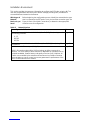
Citel EXTender 3000 Guida d'installazione
- Categoria
- Telefoni IP
- Tipo
- Guida d'installazione
Questo manuale è adatto anche per


EXTender 6000 Quick Installation Guide 2
Copyright
© Copyright 2005 Citel Technologies All rights reserved.
No part of this publication, including text, examples, diagrams, or icons, may be reproduced, transmitted,
or translated in any form or by any means, electronic, mechanical, manual, optical or otherwise, for any
purpose, without prior written permission of Citel Technologies.
Information in this publication is subject to change without notice. Citel Technologies may have patents or
pending patents applications, trademarks, copyrights, or other intellectual property rights covering subject
matter in this publication. The furnishing of this document does not give you license to these patents,
trademarks, copyrights, or other intellectual property.
Trademarks
© 2004 Citel Technologies All rights reserved.
MCK, the MCK logo, PBXgateway I, PBXgateway II, MCK EXTender 1000, MCK EXTender 3000, MCK
EXTender 4000, MCK EXTender 6000 and MCK EXTender 7000 are trademarks or registered
trademarks of Citel Technologies or its wholly-owned subsidiaries in the United States and other
jurisdictions. All other trademarks, registered trademarks and service marks are the property of their
respective owners.

EXTender 6000 Quick Installation Guide 3
Table of Contents
Table of Contents.......................................................................................................................................3
Purpose of this Document ........................................................................................................................5
Naming Convention..................................................................................................................................5
Safety Considerations ..............................................................................................................................5
Support Telephone Numbers...................................................................................................................5
Specifications.............................................................................................................................................6
Regulatory Approvals............................................................................................................................6
System Architecture..............................................................................................................................6
WAN Ports............................................................................................................................................6
Interfaces..............................................................................................................................................6
Voice.....................................................................................................................................................6
Protocols and Services.........................................................................................................................6
Electrical ...............................................................................................................................................6
Environment..........................................................................................................................................6
Dimensions...........................................................................................................................................6
Weight...................................................................................................................................................6
Prerequisites for Installation.....................................................................................................................7
Network Requirements.............................................................................................................................7
ISDN Requirements (for asynchronous connections)..............................................................................8
Information for the System Administrator.................................................................................................8
Compatible Telephones.............................................................................................................................9
Parts provided with the EXTender .........................................................................................................11
Parts not provided with the EXTender....................................................................................................11
Installation Considerations .....................................................................................................................11
Typical Installation...................................................................................................................................12
Mounting the EXTender 6000 ................................................................................................................12
Connections to the EXTender 6000.......................................................................................................13
Telephony Wiring (RJ-21) ......................................................................................................................14
VT-100 Setup ............................................................................................................................................15
Power-Up................................................................................................................................................16
LED States:.........................................................................................................................................16
Basic Configuration.................................................................................................................................17
Installation Environment.........................................................................................................................18
Synchronous-Serial (RVP_Direct)..........................................................................................................19
Prerequisites for Configuration ...........................................................................................................19
Connect Parameters...............................................................................................................................20
Procedure ...........................................................................................................................................20
WAN Port Set up....................................................................................................................................21
Settings...............................................................................................................................................21
Procedure ...........................................................................................................................................21
Setting the Sync Rate.............................................................................................................................22
Procedure ...........................................................................................................................................22
Setting the Mode (signaling protocol).................................................................................................23
Asynchronous-Serial (RVP_Direct)........................................................................................................24
Prerequisites for Configuration ...........................................................................................................24
Primary Dial Numbers.........................................................................................................................25
Procedure ...........................................................................................................................................25
WAN Mode..........................................................................................................................................26
Procedure ...........................................................................................................................................26
Setting the Async Parameters............................................................................................................26
Procedure ...........................................................................................................................................26
IP Network (RVP_IP) ................................................................................................................................28
Prerequisites for Configuration ...........................................................................................................28
TCP/UDP Requirements.....................................................................................................................28
Basic Configuration.............................................................................................................................28
RVP_Over_IP Connect Parameters.......................................................................................................29

EXTender 6000 Quick Installation Guide 4
Procedure ...........................................................................................................................................29
IP Parameters.....................................................................................................................................30
Procedure ...........................................................................................................................................30
Set Up Wizard...........................................................................................................................................31
Standard Console User Interface vs. the Setup Wizard.....................................................................31
How to access the Setup Wizard through the MI ...............................................................................31
Placing a Call............................................................................................................................................32
Using the digital telephones connected to the PBX............................................................................32
Procedure ...........................................................................................................................................32
Using the analog line connected to the EXTender.............................................................................32
Procedure ...........................................................................................................................................32
Lifeline or 911 Phone Notice ..................................................................................................................33
Remote Telephone Messages ...............................................................................................................34
Optional Configuration............................................................................................................................35
2 to 1 Configuration (RVP_Direct)..........................................................................................................36
Procedure ...........................................................................................................................................36
Setting up the Analog Port......................................................................................................................38
Procedure ...........................................................................................................................................38
Setting the Make Set Busy Key (Meridian Only)..................................................................................39
Procedure ...........................................................................................................................................39
Setting up Call-Suspend.........................................................................................................................39
Procedure ...........................................................................................................................................40
Fax Support on the Second B (Ch 2) Channel......................................................................................42
Using an MCA Adapter with a Meridian Telephone...............................................................................42
HTML Interface .........................................................................................................................................43
Procedure ...........................................................................................................................................43

EXTender 6000 Quick Installation Guide 5
Purpose of this Document
This document provides the step-by-step process for the complete installation, basic configuration, and
troubleshooting of the EXTender 6000 for Branch Offices.
Naming Convention
The EXTender 6000 is also referred to as the EXTender or the Remote Unit within this document.
Safety Considerations
IMPORTANT SAFETY INSTRUCTIONS
• Do not install this product near water.
Example: In a wet basement location.
• Do not overload wall outlets, as this can result in the risk of fire or electrical shock.
• Do not attach the power supply cord to building surfaces. Do not allow anything to rest on the power
cord. Do not place this product where anyone can step on the cord.
• Do not operate the system if chemical gas leakage is suspected in the area. Use a telephone located
in another, safe area to report the trouble.
Support Telephone Numbers
For Customer Support please contact MCK technical assistance at 1-888 454-5828 between 8:30am -
8:00pm (EST). If you are outside North America please dial 1-617-454-6192.
NOTE: RemoteConneX is not available in Europe.

EXTender 6000 Quick Installation Guide 6
Specifications
Regulatory Approvals
FCC Parts 15 & 68, Subpart B, Class B
NRTL/C CSA Standard C22.2 No.0-M91, 225-M90
CE Mark EN50081-1, EN50082-1, EN60950
Industry Canada CS-03
UL Standard 950
System Architecture
CPU Motorola 68 MH360, 33MHz
DSP 5 Analog Devices 2187, 52 MIPS
Memory
DRAM 4MB
Flash Memory 4MB
Boot ROM 512KB
WAN Ports
Protocol Synchronous-serial; Asynchronous-serial
Interface RS-232, V.35, or RS-530
Encapsulation High-level Data Link Control (HDLC)
Interfaces
Ethernet Single 10Base-T, RJ-45
Serial/WAN EIA/TIA-232, EIA/TIA-530, EIA/TIA-V35
Management Serial RS-232, DB9
PBX/KSU Up to 12 digital line interfaces over a 25 pair RJ-21 cable
Voice
Voice compression G.729a, G.711, G.726 (ADPCM 32 and ADPCM 24
Protocols and Services
LAN RVP over Internet Protocol (IP)
WAN Remote Voice Protocol (RVP™) (proprietary) over HDLC
Electrical
Line Voltage 100-240 VAC
Frequency 50-60 Hz
Max Power
Consumption 0.8 Amps
Power Input Filter IEC (with 2A fuse)
Environment
Temperature 32° - 130° F (0° - 55° C)
Relative Humidity 5 to 95%
Dimensions
17 in x 8 in 1 3/4 in (432 mm x 203 mm x 44 mm)
Weight
6 lbs 7 oz (3 kg)

EXTender 6000 Quick Installation Guide 7
Prerequisites for Installation
You must meet the following requirements before installing the EXTender 6000:
Network Requirements
• You must install and configure appropriate network terminating devices at both the corporate facility
and the branch office. Both network-terminating devices must be fully functional and both must
support an RS-232, V.35, or RS-530 synchronous, asynchronous or Voice over IP (VOIP) interface.
• If you use an asynchronous connection, you must install the appropriate ISDN Terminal Adapters
(TAs), from the list below. The TAs must be operational at both the corporate facility and the Branch
Office. This list is complete as of the release date of this document. Refer to the MCK’s Web site:
http://www.mck.com/ for the most recent list of recommended ISDN TAs. If using a synchronous
connection please see page 19 for more information.
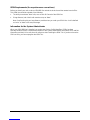
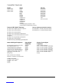
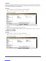
Table 1: ISDN TAs
Manufacturer
Model
3Com 3Com U.S. Robotics
Adtran ISU 2X64
ISU 128
Express NTU
Express 3000
Motorola Bitsurfr Pro (rev 1M)
Bitsurfr Pro EZ
Bitsurfr Pro for Europe
-- <MANUAL_SETUP_1>
<MANUAL_SETUP_2>
* Connect IQ 400 Series
* Multitech IWAY Hopper (Async only)
* European Use
Note: For the Async-RS 232 Dial feature to work properly for these devices, you must set up each device
to accept incoming “AT Commands”. Consult the documentation provided with each device for
proper instructions.
Provide proper wiring with adequate punchdown blocks to connect the Remote Unit to the telephones.
Follow the details in Pin Out Assignments on page 14, and provide an RJ-21 female connector.

EXTender 6000 Quick Installation Guide 8
ISDN Requirements (for asynchronous connections)
Before you install your units, order an ISDN BRI line at both the local site and the remote branch office.
This ISDN line should be capable of the following:
• The ability to make two “data” calls, one on each B Channel of the ISDN line.
• If long distance, both “data” calls must be set up as “data”.
Note: Confirm this with your long distance provider when you order your ISDN Line. A call is defined
as “voice” or “data” in the setup message.
Information for the System Administrator
When your ISDN BRI line is installed, you receive two Service Profile Identifiers (SPIDs) and two
Directory Numbers (DNs). Provide these numbers to the System Administrator. Record the SPID and DN
information and keep it in a safe place for reference when installing the ISDN TAs. If you do not have the
SPIDs or DNs, you cannot program the ISDN TAs.

EXTender 6000 Quick Installation Guide 9
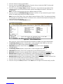
Compatible Telephones
Alcatel Avaya Ericsson
Reflexes 4023
Reflexes 4034
Reflexes 4035
6402+ *
6408+
6416D+
6424D+
8403
8410D
8410DR
8434DX
CallMaster III
CallMaster IV
CallMaster V
CallMaster VI
Gray Market
9031DCP
* This digital display telephone is NOT
recommended for administrative purposes.
Dialog 3200
Dialog 3201
Dialog 3202
Dialog 3203
Dialog 3210
Dialog 3211
Dialog 3212
Dialog 3213
AOM
Ericsson headset
Panasonic DBS Digital Telephones Panasonic DBS Supported Add-on Modules
VB-41200 DSLT Digital Single Line Telephone
VB-44210 16 key standard phone
VB-44220 22 key standard phone
VB-44223 22 key small-display speakerphone
VB-44224 22 key small-display speakerphone (voice
recognition)
VB-44225 22 key large-display speakerphone
VB-44230 34 key standard phone
VB-44233 34 key small-display speakerphone
VB-44310 EM24 - 24 Button Expansion Module
VB-44320 DSS72 - 72 Button DSS/BLF Module
Iwatsu ADIX Digital Telephones Magix Digital
Telephones Nitsuko i-Series Digital
Telephones
The EXTender will support many of the
ADIX digital telephones. It is
recommended that each telephone
connected to the EXTender have a
display. The use of display telephones
provides important status information
regarding the connection to the
PBXgateway.
Note: A minimum of one display
telephone is required on each EXTender.
IX-8KTD and IX-8KTS
IX-12KTD-2 and IX-12KTS-2
IX-24KTD and IX-24KTS
IX-MKT
IX-VTA
4424LD+
4424D+
4412D+
4406D+
4400D+
4400+
92550 - Digital Single Line
92753 - 12 Line, 22 Button, with Display
92750 - 12 Line, 22 Button, no Display
92783 - 24 Line, 34 Button, with Display
92760 - 18 Line, 28 Button, no Display
92763 - 18 Line, 28 Button, with Display
92773 - 24 Line, 34 Button, Super
Display

EXTender 6000 Quick Installation Guide 10
Nitsuko i-Series Digital
Telephones Nortel Toshiba
92550 - Digital Single Line
92753 - 12 Line, 22 Button, with Display
92750 - 12 Line, 22 Button, no Display
92783 - 24 Line, 34 Button, with Display
92760 - 18 Line, 28 Button, no Display
92763 - 18 Line, 28 Button, with Display
92773 - 24 Line, 34 Button, Super
Display
Meridian
M2006 *
M2008 *
M2216
M2317
M2616
M2616CT
M3903
M3904
M3905
Norstar
M7100 *
M7208
M7310
M7324
M7410
ATA2
T7208
T7316
T7316E
* This digital display telephone is NOT
recommended for administrative
purposes
DKT 2004
DKT 2010-SD
DKT 2020-SD

EXTender 6000 Quick Installation Guide 11
Parts provided with the EXTender
Table 2: Part Provided with the EXTender
Quantity Description
1 EXTender 6000
1 Power Cord
1 DB-25, RS-530 cable
1 DB-9 RS-232 cable
1 Cat 5 Ethernet Cable
- Mounting Hardware
2 Mounting Brackets
1 Quick Install Guide
Parts not provided with the EXTender
• Digital telephones and communication line cords are NOT supplied with this system.
Note: Use two-wire digital telephones only.
• Punchdown blocks necessary to interface between the RJ-21 connector and the remote telephones.
• 50 pin cable with male RJ-21 connectors to interface between the punchdown block and the
EXTender. (See Pin Out Assignments on page 14)
• Analog telephone line for local use, if you purchased an analog line card.
Note: The analog line card is not available outside North America.
Installation Considerations
• The system operates from 100-240 VAC, 50-60 Hz. Do not apply power to the unit until instructed to
in the installation procedures.
• Install the power supply and cabling away from high power/high RF noise devices such as computers,
fans, fluorescent ballast, or power supplies.
• Use good wiring practices. Do not run wires over fluorescent lights, computers, air conditioners, etc.,
as this can introduce noise to the modems.
• The distance from the telephones to the EXTender should NOT exceed 500 feet.

EXTender 6000 Quick Installation Guide 12
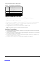
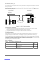
Typical Installation
The figure below shows a typical installation of the EXTender.
Public
Branch Office
Punch Block
EXTender 6000
Punch Block
PBX
Corporate Office
PBXgateway
DSU/CSU DSU/CSU
Analog Phone Line
Figure 1: Typical 6000 Installation
Mounting the EXTender 6000
You can mount the EXTender in a standard 19-inch communication rack using the brackets provided or
simply place it on a shelf within the rack.
Figure 2: Securing the Unit to a Rack

EXTender 6000 Quick Installation Guide 13
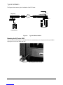
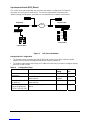
Connections to the EXTender 6000
The following figures show the required EXTender connections, A through C.
Note: Connection “D” is for synchronous or asynchronous-serial only; “E” is for connection to an analog
line; and connection “F” is for VOIP.
Figure 3: Front and Back of EXTender 6000
Table 3: EXTender Connections
Letter Label Cable Type Description
A Console DB-9 Connect to a PC COM port
Note: Set the COM port as follows: Baud
rate: 9600, Databits: 8, Parity: none,
Stopbits: 1, Software flow control: Xon/Xoff.
B - Power Connect to a 120 VAC outlet
C Telephony Interface RJ-21 Wire to a punchdown block and then to the
PBX. (See Pin Out Assignments on page 14)
D WAN1 DB-25, serial.
straight-through Connects the EXTender to a synchronous or
asynchronous- serial device (CSU/DSU or
other network device).
Note: Use an RS-530 type cable or DB-25 to
M34 cable should for high-speed links to
V.35 equipment.
E Analog (if purchased)
Note: Not available
outside of North
America.
RJ-11 Connects to an analog line for local dialing.
Note: This port does not provide PBX
functionality or features.
F LAN RJ-45 Ethernet Connects the EXTender to the LAN for
use in VOIP applications.

EXTender 6000 Quick Installation Guide 14
Telephony Wiring (RJ-21)
Table 4: Pin Out Assignments
Pin Cable
Pair Port Pin Cable
Pair Port
26
1 WH/BL
BL/WH 1 38
13 BK/GN
GN/BK 7
28
3 WH/GN
GN/WH 2 40
15 BK/SL
SL/BK 8
30
5 WH/SL
SL/WH 3 42
17 YL/OR
OR/YL 9
32
7 RD/OR
OR/RD 4 44
19 YL/BR
BR/YL 10
34
9 RD/BR
BR/RD 5 46
21 VI/BL
BL/VI 11
36
11 BK/BL
BL/BK 6 48
23 VI/GN
GN/VI 12
Wire Color Abbreviations:
BK=Black BR=Brown RD=Red OR=Orange SL=Slate
YL=Yellow GN-Breen BL-Blue VI-Violet WH=White

EXTender 6000 Quick Installation Guide 15
VT-100 Setup
Make sure the EXTender is connected as shown on page 12.
You must use communications software — for example, HyperTerminal — to configure and test the
EXTender. Attach one end of the RS-232 cable to your PC COM port and the other end to the DB-9
Console port connector on the front of the EXTender.
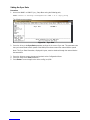
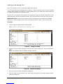
Set up HyperTerminal as follows:
A Access: Start button > Programs > Accessories > HyperTerminal folder > HyperTerminal
icon.
B When prompted for a name, type gateway and click OK.
C (Determine what port [n] you will connect to on your pxc. At the Telephone Number dialog,
select Connect using = Direct to COMn (ignore other settings) and click OK.
D At the COMn 1 Properties dialog, set the parameters to 9600, 8, none, 1 and Xon/Xoff
and click OK.
E When the HyperTerminal window appears, it is blank; that is, there is no logon prompt.
F Click on File, then Properties. Select Settings tab and go to Emulation window. Select
VT100 and click OK.
1 n is the number of the COM port on the PC.
Go to Power-Up sequence on the next page.

EXTender 6000 Quick Installation Guide 16
Power-Up
Once the VT-100 program is set up, plug the unit into an AC outlet. The device begins a series of self-
diagnostic tests, which are displayed as a series of LED flashes.
Figure 4: Back of Unit (LAN Connections)
LAN Notes:
The state for the LEDs labeled XMT (Transmit), RCV (Receive), and CLN (Collision) varies depending on
the status of the network. These LEDs are not critical for verifying the Sequence”.
LNK LED should be solid green.
If you are connecting an EXTender to an IP network, the unit requires an assigned IP address.
The Ethernet port on the Remote Unit operates on 10 megabit Ethernet networks only. It does not sup-
port 100 megabits.
Once the power-up sequence is finished, the state of the following LEDs should be Green.
LED States:
PWR Solid Green.
WAN1 Solid Green (Ready) if a synchronous device is connected to WAN 1.
Solid Orange (Ready) if an asynchronous ISDN TA is connected and accepting
commands (but there is no link up- in Call Suspend mode or has not dialed it
yet).
Port LEDs Solid Green if connected properly to the PBX.
IMPORTANT: If any of the LEDs DO NOT power as explained, refer to the System Administrator’s
Guide for troubleshooting information.
Figure 5: Front of Unit
On initial power-up (or before the config file is changed) the Management Interface (MI) asks you to run
the “Setup Wizard”.

EXTender 6000 Quick Installation Guide 17
• If you type “Yes ”, the wizard asks a series of configuration questions. (See page 31.)
• If you type “No”, the PC displays the following message:
Press “Enter” to start the EXTender shell…..
Note: If the EXTender is powered up prior to opening the terminal program, this message does not
appear.
Go to Basic Configuration on the next page.
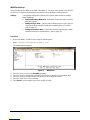
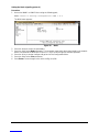
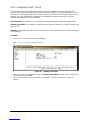
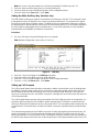
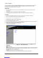
Basic Configuration
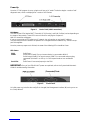
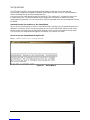
Press Enter. The MI Welcome Screen is displayed.
Figure 6: Welcome Screen
IMPORTANT TERMINAL SETTINGS
The MI requires a screen size of 24 lines X 80 columns. Make sure the Welcome Screen is bordered on
all four sides with a # symbol, as shown in the figure above.
To enlarge the screen (within the VT-100 application)
1. Click any corner of the screen.
2. Drag the screen to enlarge.
3. Check that the screen is bordered by “#” symbols.
Press any key to continue. The Main Menu is displayed.
If you already familiar with using the MI, proceed to page 18 for information on setting the parameters for
the different Network Environments.
Or……..
Press F1 for the MI Help Screen, which provides basic information for navigating through the interface.

EXTender 6000 Quick Installation Guide 18
Installation Environment
This section provides the necessary information to configure the EXTender using the MI. The
units are programmed at the factory with “default” settings providing basic parameters to
accommodate most network environments.
Which type of
Network
Device do you
have?
Before beginning the configuration process, identify the network device type
that is connected to the EXTender. Once you know the connection type, use
Figure 4: Back of Unit (LAN Connections), to determine the appropriate
checklist to use for configuration.
Table 5: Network Devices
To configure the EXTender with....... See......
a Synchronous -serial device via WAN Port(s) 1 or 2 (RVP_Direct) using one of
the following protocols:
• V. 3 5
• RS-232
• RS-530
Page 19
an Asynchronous -serial device via WAN Port(s) 1 or 2 (RVP_Direct) using RS-
232 Protocol. page 24
an IP device – via Ethernet port (RVP_IP).
* MCK’s IP-based products utilize VOIP technology to deliver remote voice
solutions. The voice quality of these solutions is dependent on variables such as
available bandwidth, network latency and quality of service (QoS) initiatives, all
of which are controlled by the network and internet service providers. Because
these variables are not our control, we cannot guarantee the performance of the
user’s IP-based remote voice solution.
page 30

EXTender 6000 Quick Installation Guide 19
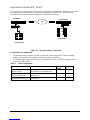
Synchronous-Serial (RVP_Direct)
This section of the manual provides the necessary information to configure the EXTender for
connection to a synchronous-serial device. The units are programmed at the factory with
“default” settings providing basic parameters to accommodate many network environments.
Public
Branch Office
Punch Block
EXTender 6000
Punch Block
PBX
Corporate Office
PBXgateway
Router
DSU/CSU DSU/CSU
Router
Figure 7: RVP_Direct Installation
Prerequisites for Configuration
• The Gateway (at the corporate site) and the EXTender (at the branch office) must be installed
properly and the network link between both devices must be operational.
• The network administrator must assign an IP address for both units if you plan to configure and test
them over a LAN or WAN.
Table 6: Configuration Steps
You must...... To...... Default
Setting Refer
to...
Set Connect
Parameters Select network type RVP_Direct page 20
Setup the WAN ports Enable WAN ports to connect to
network device. WAN 1 -
Enabled page 21
Set the Sync Rate of
the WAN port Match the data rate (sync rate) of the
network device 512,000 kbps page 22
Set the mode (interface
type) of the WAN port.
(v.35, RS-232, RS-530)
Match the interface type of the network
device. V.35 page 23

EXTender 6000 Quick Installation Guide 20
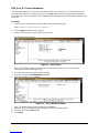
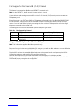
Connect Parameters
The EXTender utilizes a direct serial connection to provide remote user connectivity. This means that the
wide area network (WAN) port is plugged directly into a network device. Use the RVP Direct menu to
identify the WAN port (WAN 1 or WAN 2) that is the main or “primary” port.
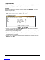
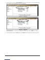
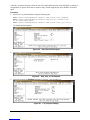
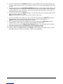
Procedure
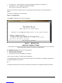
Before beginning this procedure ensure you have set the Connect Type to RVP_Direct. This item is
located on the Connect menu.
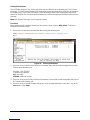
1. Access the Connect Menu from the Main Menu using the following path:
Path: Remote->Configuration->Connect->RVP_Direct
The following menu appears:
Figure 8: RVP_Direct Menu
2. Press the Æ key and È key to the Primary Interface parameter. This is the main WAN port that
connects the Remote Unit to the network device.
3. Press theÆ key to scroll through the choices.
4. Press the È key to the Secondary Interface parameter. This identifies the secondary WAN port. This
parameter is normally set to None.
5. Press the Èkey to the Utilization parameter. This parameter is a numeric value that represents the
percentage of bandwidth used by the remote unit. Contact the system administrator for more
information on setting this parameter.
6. Press the Åkey to accept changes and go back to the Configuration Menu. Press the ← key to the
Save option. Press Enter.
La pagina si sta caricando...
La pagina si sta caricando...
La pagina si sta caricando...
La pagina si sta caricando...
La pagina si sta caricando...
La pagina si sta caricando...
La pagina si sta caricando...
La pagina si sta caricando...
La pagina si sta caricando...
La pagina si sta caricando...
La pagina si sta caricando...
La pagina si sta caricando...
La pagina si sta caricando...
La pagina si sta caricando...
La pagina si sta caricando...
La pagina si sta caricando...
La pagina si sta caricando...
La pagina si sta caricando...
La pagina si sta caricando...
La pagina si sta caricando...
La pagina si sta caricando...
La pagina si sta caricando...
La pagina si sta caricando...
-
 1
1
-
 2
2
-
 3
3
-
 4
4
-
 5
5
-
 6
6
-
 7
7
-
 8
8
-
 9
9
-
 10
10
-
 11
11
-
 12
12
-
 13
13
-
 14
14
-
 15
15
-
 16
16
-
 17
17
-
 18
18
-
 19
19
-
 20
20
-
 21
21
-
 22
22
-
 23
23
-
 24
24
-
 25
25
-
 26
26
-
 27
27
-
 28
28
-
 29
29
-
 30
30
-
 31
31
-
 32
32
-
 33
33
-
 34
34
-
 35
35
-
 36
36
-
 37
37
-
 38
38
-
 39
39
-
 40
40
-
 41
41
-
 42
42
-
 43
43


Citel EXTender 3000 Guida d'installazione
- Categoria
- Telefoni IP
- Tipo
- Guida d'installazione
- Questo manuale è adatto anche per
in altre lingue
Altri documenti
-
Comtech EF Data Memotec NetPerformer SDM-8400 Hardware Installation Manual
-
Juniper J6350 Getting Started Manual
-
Motorola Canopy Powerline MU Manuale utente
-
HP 3000 Router Series Guida Rapida
-
3com HomeConnect 3CP4130 Manuale utente
-
Edimax BR-6228NS V2 Manuale utente
-
-
D-Link DIR-878 Manuale utente
-
-
Cisco 7606 Guida d'installazione