
Complete Hardware Guide for EX 3200 and EX 4200
Switches
Juniper Networks, Inc.
1194 North Mathilda Avenue
Sunnyvale, California 94089
USA
408-745-2000
www.juniper.net
Part Number: , Revision R1

This product includes the Envoy SNMP Engine, developed by Epilogue Technology, an Integrated Systems Company. Copyright © 1986-1997, Epilogue
Technology Corporation. All rights reserved. This program and its documentation were developed at private expense, and no part of them is in the public
domain.
This product includes memory allocation software developed by Mark Moraes, copyright © 1988, 1989, 1993, University of Toronto.
This product includes FreeBSD software developed by the University of California, Berkeley, and its contributors. All of the documentation and software
included in the 4.4BSD and 4.4BSD-Lite Releases is copyrighted by the Regents of the University of California. Copyright © 1979, 1980, 1983, 1986, 1988,
1989, 1991, 1992, 1993, 1994. The Regents of the University of California. All rights reserved.
GateD software copyright © 1995, the Regents of the University. All rights reserved. Gate Daemon was originated and developed through release 3.0 by
Cornell University and its collaborators. Gated is based on Kirton’s EGP, UC Berkeley’s routing daemon (routed), and DCN’s HELLO routing protocol.
Development of Gated has been supported in part by the National Science Foundation. Portions of the GateD software copyright © 1988, Regents of the
University of California. All rights reserved. Portions of the GateD software copyright © 1991, D. L. S. Associates.
This product includes software developed by Maker Communications, Inc., copyright © 1996, 1997, Maker Communications, Inc.
Juniper Networks, the Juniper Networks logo, JUNOS, NetScreen, ScreenOS, and Steel-Belted Radius are registered trademarks of Juniper Networks, Inc. in
the United States and other countries. JUNOSe is a trademark of Juniper Networks, Inc. All other trademarks, service marks, registered trademarks, or
registered service marks are the property of their respective owners.
Juniper Networks assumes no responsibility for any inaccuracies in this document. Juniper Networks reserves the right to change, modify, transfer, or
otherwise revise this publication without notice.
Products made or sold by Juniper Networks or components thereof might be covered by one or more of the following patents that are owned by or licensed
to Juniper Networks: U.S. Patent Nos. 5,473,599, 5,905,725, 5,909,440, 6,192,051, 6,333,650, 6,359,479, 6,406,312, 6,429,706, 6,459,579, 6,493,347,
6,538,518, 6,538,899, 6,552,918, 6,567,902, 6,578,186, and 6,590,785.
EX 3200 and EX 4200 Switches Complete Hardware Guide for EX 3200 and EX 4200 Switches
Copyright © 2008, Juniper Networks, Inc.
All rights reserved. Printed in USA.
Writing: Appumon Joseph, Aviva Garrett, Hareesh Kumar K N, Keldyn West
Editing: Cindy Martin
Illustration: Faith Bradford Brown
Cover Design:
Revision History
15 March 2008—Revision 9.0 R1
28 April 2008—Revision 9.1 R1
12 August 2008—Revision 9.2 R1
The information in this document is current as of the date listed in the revision history.
YEAR 2000 NOTICE
Juniper Networks hardware and software products are Year 2000 compliant. The JUNOS software has no known time-related limitations through the year
2038. However, the NTP application is known to have some difficulty in the year 2036.
SOFTWARE LICENSE
The terms and conditions for using this software are described in the software license contained in the acknowledgment to your purchase order or, to the
extent applicable, to any reseller agreement or end-user purchase agreement executed between you and Juniper Networks. By using this software, you
indicate that you understand and agree to be bound by those terms and conditions.
Generally speaking, the software license restricts the manner in which you are permitted to use the software and may contain prohibitions against certain
uses. The software license may state conditions under which the license is automatically terminated. You should consult the license for further details.
For complete product documentation, please see the Juniper Networks Web site at www.juniper.net/techpubs.
ii ■

END USER LICENSE AGREEMENT
READ THIS END USER LICENSE AGREEMENT (“AGREEMENT”) BEFORE DOWNLOADING, INSTALLING, OR USING THE SOFTWARE. BY DOWNLOADING,
INSTALLING, OR USING THE SOFTWARE OR OTHERWISE EXPRESSING YOUR AGREEMENT TO THE TERMS CONTAINED HEREIN, YOU (AS CUSTOMER
OR IF YOU ARE NOT THE CUSTOMER, AS A REPRESENTATIVE/AGENT AUTHORIZED TO BIND THE CUSTOMER) CONSENT TO BE BOUND BY THIS
AGREEMENT. IF YOU DO NOT OR CANNOT AGREE TO THE TERMS CONTAINED HEREIN, THEN (A) DO NOT DOWNLOAD, INSTALL, OR USE THE SOFTWARE,
AND (B) YOU MAY CONTACT JUNIPER NETWORKS REGARDING LICENSE TERMS.
1. The Parties. The parties to this Agreement are (i) Juniper Networks, Inc. (if the Customer’s principal office is located in the Americas) or Juniper Networks
(Cayman) Limited (if the Customer’s principal office is located outside the Americas) (such applicable entity being referred to herein as “Juniper”), and (ii)
the person or organization that originally purchased from Juniper or an authorized Juniper reseller the applicable license(s) for use of the Software (“Customer”)
(collectively, the “Parties”).
2. The Software. In this Agreement, “Software” means the program modules and features of the Juniper or Juniper-supplied software, for which Customer
has paid the applicable license or support fees to Juniper or an authorized Juniper reseller, or which was embedded by Juniper in equipment which Customer
purchased from Juniper or an authorized Juniper reseller. “Software” also includes updates, upgrades and new releases of such software. “Embedded
Software” means Software which Juniper has embedded in or loaded onto the Juniper equipment and any updates, upgrades, additions or replacements
which are subsequently embedded in or loaded onto the equipment.
3. License Grant. Subject to payment of the applicable fees and the limitations and restrictions set forth herein, Juniper grants to Customer a non-exclusive
and non-transferable license, without right to sublicense, to use the Software, in executable form only, subject to the following use restrictions:
a. Customer shall use Embedded Software solely as embedded in, and for execution on, Juniper equipment originally purchased by Customer from Juniper
or an authorized Juniper reseller.
b. Customer shall use the Software on a single hardware chassis having a single processing unit, or as many chassis or processing units for which Customer
has paid the applicable license fees; provided, however, with respect to the Steel-Belted Radius or Odyssey Access Client software only, Customer shall use
such Software on a single computer containing a single physical random access memory space and containing any number of processors. Use of the
Steel-Belted Radius or IMS AAA software on multiple computers or virtual machines (e.g., Solaris zones) requires multiple licenses, regardless of whether
such computers or virtualizations are physically contained on a single chassis.
c. Product purchase documents, paper or electronic user documentation, and/or the particular licenses purchased by Customer may specify limits to
Customer’s use of the Software. Such limits may restrict use to a maximum number of seats, registered endpoints, concurrent users, sessions, calls,
connections, subscribers, clusters, nodes, realms, devices, links, ports or transactions, or require the purchase of separate licenses to use particular features,
functionalities, services, applications, operations, or capabilities, or provide throughput, performance, configuration, bandwidth, interface, processing,
temporal, or geographical limits. In addition, such limits may restrict the use of the Software to managing certain kinds of networks or require the Software
to be used only in conjunction with other specific Software. Customer’s use of the Software shall be subject to all such limitations and purchase of all applicable
licenses.
d. For any trial copy of the Software, Customer’s right to use the Software expires 30 days after download, installation or use of the Software. Customer
may operate the Software after the 30-day trial period only if Customer pays for a license to do so. Customer may not extend or create an additional trial
period by re-installing the Software after the 30-day trial period.
e. The Global Enterprise Edition of the Steel-Belted Radius software may be used by Customer only to manage access to Customer’s enterprise network.
Specifically, service provider customers are expressly prohibited from using the Global Enterprise Edition of the Steel-Belted Radius software to support any
commercial network access services.
The foregoing license is not transferable or assignable by Customer. No license is granted herein to any user who did not originally purchase the applicable
license(s) for the Software from Juniper or an authorized Juniper reseller.
4. Use Prohibitions. Notwithstanding the foregoing, the license provided herein does not permit the Customer to, and Customer agrees not to and shall
not: (a) modify, unbundle, reverse engineer, or create derivative works based on the Software; (b) make unauthorized copies of the Software (except as
necessary for backup purposes); (c) rent, sell, transfer, or grant any rights in and to any copy of the Software, in any form, to any third party; (d) remove
any proprietary notices, labels, or marks on or in any copy of the Software or any product in which the Software is embedded; (e) distribute any copy of
the Software to any third party, including as may be embedded in Juniper equipment sold in the secondhand market; (f) use any ‘locked’ or key-restricted
feature, function, service, application, operation, or capability without first purchasing the applicable license(s) and obtaining a valid key from Juniper, even
if such feature, function, service, application, operation, or capability is enabled without a key; (g) distribute any key for the Software provided by Juniper
to any third party; (h) use the Software in any manner that extends or is broader than the uses purchased by Customer from Juniper or an authorized Juniper
reseller; (i) use Embedded Software on non-Juniper equipment; (j) use Embedded Software (or make it available for use) on Juniper equipment that the
Customer did not originally purchase from Juniper or an authorized Juniper reseller; (k) disclose the results of testing or benchmarking of the Software to
any third party without the prior written consent of Juniper; or (l) use the Software in any manner other than as expressly provided herein.
5. Audit. Customer shall maintain accurate records as necessary to verify compliance with this Agreement. Upon request by Juniper, Customer shall furnish
such records to Juniper and certify its compliance with this Agreement.
■ iii

6. Confidentiality. The Parties agree that aspects of the Software and associated documentation are the confidential property of Juniper. As such, Customer
shall exercise all reasonable commercial efforts to maintain the Software and associated documentation in confidence, which at a minimum includes
restricting access to the Software to Customer employees and contractors having a need to use the Software for Customer’s internal business purposes.
7. Ownership. Juniper and Juniper’s licensors, respectively, retain ownership of all right, title, and interest (including copyright) in and to the Software,
associated documentation, and all copies of the Software. Nothing in this Agreement constitutes a transfer or conveyance of any right, title, or interest in
the Software or associated documentation, or a sale of the Software, associated documentation, or copies of the Software.
8. Warranty, Limitation of Liability, Disclaimer of Warranty. The warranty applicable to the Software shall be as set forth in the warranty statement that
accompanies the Software (the “Warranty Statement”). Nothing in this Agreement shall give rise to any obligation to support the Software. Support services
may be purchased separately. Any such support shall be governed by a separate, written support services agreement. TO THE MAXIMUM EXTENT PERMITTED
BY LAW, JUNIPER SHALL NOT BE LIABLE FOR ANY LOST PROFITS, LOSS OF DATA, OR COSTS OR PROCUREMENT OF SUBSTITUTE GOODS OR SERVICES,
OR FOR ANY SPECIAL, INDIRECT, OR CONSEQUENTIAL DAMAGES ARISING OUT OF THIS AGREEMENT, THE SOFTWARE, OR ANY JUNIPER OR
JUNIPER-SUPPLIED SOFTWARE. IN NO EVENT SHALL JUNIPER BE LIABLE FOR DAMAGES ARISING FROM UNAUTHORIZED OR IMPROPER USE OF ANY
JUNIPER OR JUNIPER-SUPPLIED SOFTWARE. EXCEPT AS EXPRESSLY PROVIDED IN THE WARRANTY STATEMENT TO THE EXTENT PERMITTED BY LAW,
JUNIPER DISCLAIMS ANY AND ALL WARRANTIES IN AND TO THE SOFTWARE (WHETHER EXPRESS, IMPLIED, STATUTORY, OR OTHERWISE), INCLUDING
ANY IMPLIED WARRANTY OF MERCHANTABILITY, FITNESS FOR A PARTICULAR PURPOSE, OR NONINFRINGEMENT. IN NO EVENT DOES JUNIPER
WARRANT THAT THE SOFTWARE, OR ANY EQUIPMENT OR NETWORK RUNNING THE SOFTWARE, WILL OPERATE WITHOUT ERROR OR INTERRUPTION,
OR WILL BE FREE OF VULNERABILITY TO INTRUSION OR ATTACK. In no event shall Juniper’s or its suppliers’ or licensors’ liability to Customer, whether
in contract, tort (including negligence), breach of warranty, or otherwise, exceed the price paid by Customer for the Software that gave rise to the claim, or
if the Software is embedded in another Juniper product, the price paid by Customer for such other product. Customer acknowledges and agrees that Juniper
has set its prices and entered into this Agreement in reliance upon the disclaimers of warranty and the limitations of liability set forth herein, that the same
reflect an allocation of risk between the Parties (including the risk that a contract remedy may fail of its essential purpose and cause consequential loss),
and that the same form an essential basis of the bargain between the Parties.
9. Termination. Any breach of this Agreement or failure by Customer to pay any applicable fees due shall result in automatic termination of the license
granted herein. Upon such termination, Customer shall destroy or return to Juniper all copies of the Software and related documentation in Customer’s
possession or control.
10. Taxes. All license fees payable under this agreement are exclusive of tax. Customer shall be responsible for paying Taxes arising from the purchase of
the license, or importation or use of the Software. If applicable, valid exemption documentation for each taxing jurisdiction shall be provided to Juniper prior
to invoicing, and Customer shall promptly notify Juniper if their exemption is revoked or modified. All payments made by Customer shall be net of any
applicable withholding tax. Customer will provide reasonable assistance to Juniper in connection with such withholding taxes by promptly: providing Juniper
with valid tax receipts and other required documentation showing Customer’s payment of any withholding taxes; completing appropriate applications that
would reduce the amount of withholding tax to be paid; and notifying and assisting Juniper in any audit or tax proceeding related to transactions hereunder.
Customer shall comply with all applicable tax laws and regulations, and Customer will promptly pay or reimburse Juniper for all costs and damages related
to any liability incurred by Juniper as a result of Customer’s non-compliance or delay with its responsibilities herein. Customer’s obligations under this
Section shall survive termination or expiration of this Agreement.
11. Export. Customer agrees to comply with all applicable export laws and restrictions and regulations of any United States and any applicable foreign
agency or authority, and not to export or re-export the Software or any direct product thereof in violation of any such restrictions, laws or regulations, or
without all necessary approvals. Customer shall be liable for any such violations. The version of the Software supplied to Customer may contain encryption
or other capabilities restricting Customer’s ability to export the Software without an export license.
12. Commercial Computer Software. The Software is “commercial computer software” and is provided with restricted rights. Use, duplication, or disclosure
by the United States government is subject to restrictions set forth in this Agreement and as provided in DFARS 227.7201 through 227.7202-4, FAR 12.212,
FAR 27.405(b)(2), FAR 52.227-19, or FAR 52.227-14(ALT III) as applicable.
13. Interface Information. To the extent required by applicable law, and at Customer's written request, Juniper shall provide Customer with the interface
information needed to achieve interoperability between the Software and another independently created program, on payment of applicable fee, if any.
Customer shall observe strict obligations of confidentiality with respect to such information and shall use such information in compliance with any applicable
terms and conditions upon which Juniper makes such information available.
14. Third Party Software. Any licensor of Juniper whose software is embedded in the Software and any supplier of Juniper whose products or technology
are embedded in (or services are accessed by) the Software shall be a third party beneficiary with respect to this Agreement, and such licensor or vendor
shall have the right to enforce this Agreement in its own name as if it were Juniper. In addition, certain third party software may be provided with the
Software and is subject to the accompanying license(s), if any, of its respective owner(s). To the extent portions of the Software are distributed under and
subject to open source licenses obligating Juniper to make the source code for such portions publicly available (such as the GNU General Public License
(“GPL”) or the GNU Library General Public License (“LGPL”)), Juniper will make such source code portions (including Juniper modifications, as appropriate)
available upon request for a period of up to three years from the date of distribution. Such request can be made in writing to Juniper Networks, Inc., 1194
N. Mathilda Ave., Sunnyvale, CA 94089, ATTN: General Counsel. You may obtain a copy of the GPL at http://www.gnu.org/licenses/gpl.html, and
a copy of the LGPL at http://www.gnu.org/licenses/lgpl.html.
15. Miscellaneous. This Agreement shall be governed by the laws of the State of California without reference to its conflicts of laws principles. The provisions
of the U.N. Convention for the International Sale of Goods shall not apply to this Agreement. For any disputes arising under this Agreement, the Parties
hereby consent to the personal and exclusive jurisdiction of, and venue in, the state and federal courts within Santa Clara County, California. This Agreement
constitutes the entire and sole agreement between Juniper and the Customer with respect to the Software, and supersedes all prior and contemporaneous
iv ■

agreements relating to the Software, whether oral or written (including any inconsistent terms contained in a purchase order), except that the terms of a
separate written agreement executed by an authorized Juniper representative and Customer shall govern to the extent such terms are inconsistent or conflict
with terms contained herein. No modification to this Agreement nor any waiver of any rights hereunder shall be effective unless expressly assented to in
writing by the party to be charged. If any portion of this Agreement is held invalid, the Parties agree that such invalidity shall not affect the validity of the
remainder of this Agreement. This Agreement and associated documentation has been written in the English language, and the Parties agree that the English
version will govern. (For Canada: Les parties aux présentés confirment leur volonté que cette convention de même que tous les documents y compris tout
avis qui s'y rattaché, soient redigés en langue anglaise. (Translation: The parties confirm that this Agreement and all related documentation is and will be
in the English language)).
■ v

vi ■

Table of Contents
About This Topic Collection xvii
How To Use This Guide ................................................................................xvii
List of EX-series Guides for JUNOS 9.2 .........................................................xvii
Downloading Software ................................................................................xviii
Documentation Symbols Key .......................................................................xix
Documentation Feedback ..............................................................................xx
Getting Support .............................................................................................xx
Part 1 Switch Overview
Chapter 1 Switch Overview 3
Switch Description ..........................................................................................3
EX-series Switch Hardware Overview .......................................................3
EX-series Switch Types .......................................................................3
EX 3200 Switches ...............................................................................4
EX 4200 Switches ...............................................................................4
Uplink Modules ..................................................................................5
Power over Ethernet (PoE) Ports ........................................................5
EX 3200 Switch Models ............................................................................6
EX 4200 Switch Models ............................................................................6
Hardware Components and Specifications ......................................................7
EX-series Switch Chassis Physical Specifications .......................................7
Field-Replaceable Units in EX-series Switches .........................................99
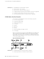
EX 3200 Switch—Front-Panel Description ................................................9
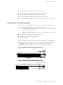
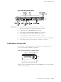
EX 3200 Switch—Rear-Panel Description ...............................................10
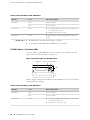
EX 4200 Switch—Front-Panel Description ..............................................11
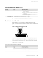
EX 4200 Switch—Rear-Panel Description ...............................................12
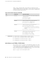
EX 3200 Switch—Front-Panel LEDs ........................................................13
EX 4200 Switch—Front-Panel LEDs ........................................................14
EX-series Switch—Network Port LEDs ....................................................15
Uplink Modules in an EX 3200 or EX 4200 Switch ..................................16
EX-series Switch—SFP Uplink Module Port LEDs ....................................18
EX-series Switch—XFP Uplink Module Port LEDs ....................................19
Optical Interface Support—EX 3200 and EX 4200 Switches ...................21
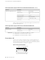
EX-series Switch—LCD ...........................................................................24
USB Port Specifications for an EX-series Switch ......................................26
Power Supply in EX 3200 and EX 4200 Switches ...................................27
AC Power Supply LEDs in EX 3200 and EX 4200 Switches .....................30
Table of Contents ■ vii

Cooling System in an EX 3200 Switch ....................................................30
DC Power Supply LEDs in EX 3200 and EX 4200 Switches .....................32
Cooling System in an EX 4200 Switch ....................................................32
EX-series Switch—Console Port Connector Pinout Information ..............34
EX-series Switch—Management Port Connector Pinout Information ......35
Uplink Modules Connector Pinout Information .......................................35
Virtual Chassis Ports Connector Pinout Information ................................42
Field-Replaceable Units (FRUs) ......................................................................45
Field-Replaceable Units in EX-series Switches .........................................99
Part 2 Setting Up the Switch
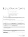
Chapter 2 Preparing the Site for Switch Installation 49
Site Preparation Checklist ..............................................................................49
Site Preparation Checklist for EX-series Switches ....................................49
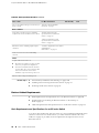
Rack or Cabinet Requirements ......................................................................50
Rack Requirements and Specifications for an EX-series Switch ...............50
Requirements for Mounting an EX-series Switch on the Desktop or
Wall ..................................................................................................52
Cabinet Requirements and Specifications for an EX-series Switch ..........52
Clearance Requirements ...............................................................................52
Clearance Requirements for Airflow and Hardware Maintenance ...........52
Electrical and Power Requirements ...............................................................54
Power Specifications and Requirements for an EX-series Switch ............54
Site Electrical Wiring Guidelines ..............................................................55
AC Power, Connection, and Power Cord Specifications ..........................56
Network Cable Specifications ........................................................................57
Network Cable Specifications ..................................................................57
Virtual Chassis Requirements ........................................................................58
Understanding Virtual Chassis Hardware Configuration ..........................58
Planning the Virtual Chassis ....................................................................58
Chapter 3 Installing the Switch 61
Installing and Connecting an EX-series Switch ..............................................61
Unpacking the Switch ....................................................................................62
Unpacking an EX-series Switch ...............................................................62
Installing the Switch ......................................................................................64
Attaching Mounting Brackets to an EX-series Switch ...............................64
Mounting an EX-series Switch .................................................................65
Mounting an EX-series Switch on a Desk or Other Level Surface ............66
Mounting an EX-series Switch on a Rack or Cabinet ...............................67
viii ■ Table of Contents
Complete Hardware Guide for EX 3200 and EX 4200 Switches

Mounting an EX 3200 or EX 4200 Switch on a Wall ...............................69
Virtual Chassis Cabling Configuration Examples .....................................72
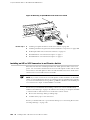
Adding a New Switch to an Existing Virtual Chassis Configuration (CLI
Procedure) ........................................................................................75
Adding a New Switch to an Existing Virtual Chassis Configuration
Within the Same Wiring Closet ..................................................75
Adding a New Switch from a Different Wiring Closet to an Existing
Virtual Chassis Configuration .....................................................76
Connecting Earth Ground to an EX-series Switch ....................................78
Connecting AC Power to an EX 3200 or EX 4200 Switch ........................79
Connecting DC Power to an EX 3200 or EX 4200 Switch ........................81
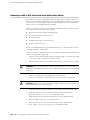
Connecting an EX-series Switch to a Network for Out-of-Band
Management ....................................................................................85
Connecting an EX-series Switch to a Management Console ....................86
Connecting a Virtual Chassis Cable to an EX 4200 Switch .......................88
Chapter 4 Connecting the Switch and Performing Initial Configuration 91
Connecting and Configuring an EX-series Switch ..........................................91
Connecting and Configuring the EX-series Switch (CLI Procedure) ..........91
Connecting and Configuring the EX-series Switch (J-Web Procedure) ......92
Part 3 Hardware Maintenance, Replacement, and Troubleshooting
Chapter 5 Replacing Hardware Components 99
Field-Replaceable Units in EX-series Switches ...............................................99
Installing and Removing EX-series Switch Hardware Components ..............100
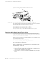
Installing an Uplink Module in an EX-series Switch .....................................101
Removing an Uplink Module from an EX-series Switch ...............................102
Installing an SFP or XFP Transceiver in an EX-series Switch ........................104
Removing an SFP or XFP Transceiver from an EX-series Switch .................106
Installing a Power Supply in an EX-series Switch .........................................107
Removing a Power Supply from an EX-series Switch ..................................108
Installing a Fan Tray in an EX-series Switch ................................................110
Removing a Fan Tray from an EX-series Switch ..........................................112
Disconnecting a Virtual Chassis Cable from an EX-series Switch .................113
Replacing a Member Switch of a Virtual Chassis Configuration (CLI
Procedure) ............................................................................................114
Remove, Repair, and Reinstall the Same Switch ...................................115
Remove a Member Switch, Replace with a Different Switch, and Reapply
the Old Configuration .....................................................................115
Remove a Member Switch and Make Its Member ID Available for
Reassignment to a Different Switch ................................................116
Table of Contents ■ ix
Table of Contents

Chapter 6 Contacting Customer Support and Returning Hardware 117
Returning an EX-series Switch or Component for Repair or Replacement ....117
Locating an EX-series Switch or Switch Component Serial Number .............117
Listing the Switch and Switch Components Details with the CLI ...........118
Locating EX 3200 and EX 4200 Chassis Serial Number Labels ..............118
Locating Switch FRU Component Serial Numbers .................................119
Contacting Customer Support to Obtain Return Materials Authorization .....119
Packing an EX-series Switch or Component for Shipping ............................120
Packing an EX-series Switch for Shipping .............................................121
Packing EX-series Switch Components for Shipping .............................122
Part 4 Safety and Regulatory Compliance Information
Chapter 7 Safety and Regulatory Compliance Information 125
Compliance .................................................................................................125
Agency Approvals .................................................................................125
Compliance Statements for EMC Requirements ....................................126
Compliance Statements for Acoustic Noise ...........................................128
Safety Information ......................................................................................128
General Warnings .................................................................................128
Definitions of Safety Warning Levels ..............................................128
General Safety Guidelines and Warnings ........................................130
Maintenance and Operational Safety Guidelines and Warnings ......131
Preventing Electrostatic Discharge Damage ...................................138
Telecommunication Line Cord Warning .........................................140
Qualified Personnel Warning ..........................................................140
Radiation and Laser Warnings ..............................................................141
Radiation from Open Port Apertures Warning ................................141
Laser and LED Safety Guidelines and Warnings ..............................143
Installation Warnings ............................................................................146
Installation Instructions Warning ....................................................146
Chassis Lifting Guidelines ...............................................................147
Rack-Mounting Requirements and Warnings ..................................147
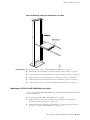
Wall-Mounting Requirements and Warnings ..................................151
Ramp Warning ...............................................................................152
Power and Electrical Warnings .............................................................152
General Electrical Safety Guidelines ................................................153
AC Power Electrical Safety Guidelines ............................................154
In Case of Electrical Accident .........................................................155
Power Disconnection Warning .......................................................156
Multiple Power Supplies Disconnection Warning ............................156
DC Power Electrical Safety Guidelines for EX 3200 and EX 4200
Switches ..................................................................................157
DC Power Grounding Requirements and Warning for EX 3200 and
EX 4200 Switches ....................................................................158
x ■ Table of Contents
Complete Hardware Guide for EX 3200 and EX 4200 Switches

DC Power Wiring Sequence Warning for EX 3200 and EX 4200
Switches ..................................................................................159
DC Power Wiring Terminations Warning for EX 3200 and EX 4200
Switches ..................................................................................160
DC Power Disconnection Warning for EX 3200 and EX 4200
Switches ..................................................................................161
Grounded Equipment Warning .......................................................163
Power Sources for Redundant Power Supplies ...............................164
TN Power Warning .........................................................................164
Warning Statement for Norway and Sweden ..................................165
Part 5 Index
Index ...........................................................................................................169
Table of Contents ■ xi
Table of Contents

xii ■ Table of Contents
Complete Hardware Guide for EX 3200 and EX 4200 Switches

List of Figures
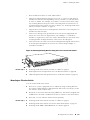
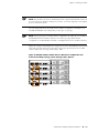
Figure 1: EX 3200 Switch with 48 Gigabit Ethernet Ports ................................9
Figure 2: EX 3200 Switch with 24 Gigabit Ethernet Ports ................................9
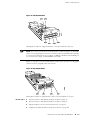
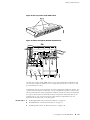
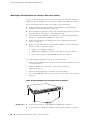
Figure 3: EX 3200 Switch Rear Panel ............................................................10
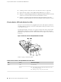
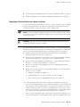
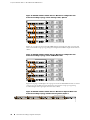
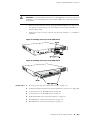
Figure 4: EX 4200 Switch with 48 Gigabit Ethernet Ports ..............................11
Figure 5: EX 4200 Switch with 24 Gigabit Ethernet Ports ..............................11
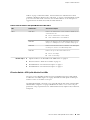
Figure 6: EX 4200-24F Switch with 24 SFP Ports ..........................................12
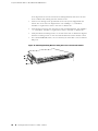
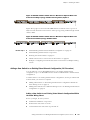
Figure 7: EX 4200 Switch Rear Panel ............................................................13
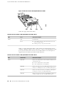
Figure 8: Front Panel LEDs in an EX 3200 Switch .........................................13
Figure 9: Front Panel LEDs in an EX 4200 Switch .........................................14
Figure 10: EX-series Switch—Network Port LEDs ..........................................25
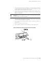
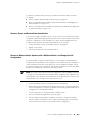
Figure 11: SFP Uplink Module .......................................................................17
Figure 12: XFP Uplink Module .......................................................................17
Figure 13: EX-series Switch—SFP Uplink Module Port LEDs ..........................18
Figure 14: EX-series Switch—XFP Uplink Module Port LEDs .........................20
Figure 15: LCD on an EX-series Switch ..........................................................24
Figure 16: EX-series Switch—Network Port LEDs ..........................................25
Figure 17: 320 W AC Power Supply in EX 3200 and EX 4200 Switches ........28
Figure 18: 600 W and 930 W AC Power Supplies in EX 3200 and EX 4200
Switches .................................................................................................28
Figure 19: DC Power Supply in EX 3200 and EX 4200 Switches ...................28
Figure 20: Fan Tray Used in an EX 3200 Switch ............................................31
Figure 21: Airflow Through the EX 3200 Switch Chassis ...............................31
Figure 22: Fan Tray Used in an EX 4200 Switch ............................................33
Figure 23: Airflow Through the EX 4200 Switch Chassis ...............................33
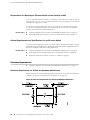
Figure 24: Clearance Requirements for Airflow and Hardware
Maintenance ...........................................................................................52
Figure 25: Airflow Through the EX 3200 Switch Chassis ...............................53
Figure 26: Airflow Through the EX 4200 Switch Chassis ...............................54
Figure 27: AC Plug Types ..............................................................................57
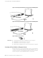
Figure 28: Unpacking an EX-series Switch .....................................................63
Figure 29: Attaching Mounting Brackets Along the Front of an EX-series
Switch .....................................................................................................65
Figure 30: Attaching Rubber Feet to the EX-series Switch Chassis .................66
Figure 31: Attaching Mounting Brackets Along the Front of an EX-series
Switch .....................................................................................................68
Figure 32: Mounting an EX-series Switch Chassis on a Rack ..........................69
Figure 33: Attaching Wall-Mount Brackets to the EX-series Switch
Chassis ....................................................................................................71
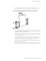
Figure 34: Mounting the EX-series Switch on the Wall ...................................72
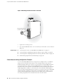
Figure 35: EX 4200 Switches Virtual Chassis—Mounted on a Single Rack and
Connected in a Ring Topology—Short and Long Cables, Option 1 ..........73
List of Figures ■ xiii

Figure 36: EX 4200 Switches Virtual Chassis—Mounted on a Single Rack and
Connected in a Ring Topology—Short and Long Cables, Option 2 ..........74
Figure 37: EX 4200 Switches Virtual Chassis—Mounted on a Single Rack and
Connected in a Ring Topology—Short and Medium Cables .....................74
Figure 38: EX 4200 Switches Virtual Chassis—Mounted on Adjacent Racks
and Connected in a Ring Topology—Medium and Long Cables, Option
1 .............................................................................................................74
Figure 39: EX 4200 Switches Virtual Chassis—Mounted on Adjacent Racks
and Connected in a Ring Topology—Medium and Long Cables, Option
2 .............................................................................................................75
Figure 40: EX 4200 Switches Virtual Chassis—Mounted on Adjacent Racks
and Connected in a Chain Topology—Medium Cables ............................75
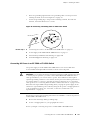
Figure 41: Connecting a Grounding Cable to an EX-series Switch ..................79
Figure 42: Connecting the AC Power Cord Retainer Clip to an AC Power
Supply in an EX 3200 or EX 4200 Switch ...............................................81
Figure 43: Connecting an AC Power Cord to an AC Power Supply in an
EX 3200 or EX 4200 Switch ....................................................................81
Figure 44: DC Power Supply in EX 3200 and EX 4200 Switches ...................82
Figure 45: Removing the Terminal Block Cover in a DC Power Supply in
EX 3200 and EX 4200 Switches ..............................................................83
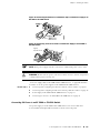
Figure 46: Securing Ring Lugs to the Terminals on the DC Power Supply in
EX 3200 and EX 4200 Switches ..............................................................85
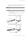
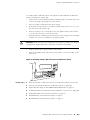
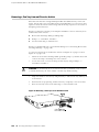
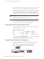
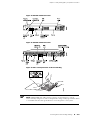
Figure 47: Connecting an EX 3200 Switch to a Network for Out-of-Band
Management ...........................................................................................86
Figure 48: Connecting an EX 4200 Switch to a Network for Out-of-Band
Management ...........................................................................................86
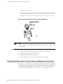
Figure 49: Ethernet Cable Connector .............................................................88
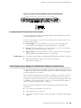
Figure 50: Connecting an EX 3200 Switch to a Management Console ...........87
Figure 51: Connecting an EX 4200 Switch to a Management Console ...........87
Figure 52: Ethernet Cable Connector .............................................................88
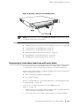
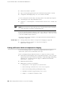
Figure 53: Connecting a Virtual Chassis Cable to an EX 4200 Switch ............89
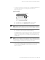
Figure 54: LCD Panel .....................................................................................93
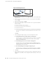
Figure 55: Connecting PC to Port 0 ...............................................................94
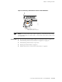
Figure 56: Installing an Uplink Module in an EX-series Switch .....................102
Figure 57: Sliding the Screwdriver to the Narrow Part of the Keyhole .........103
Figure 58: Removing an Uplink Module from an EX-series Switch ..............104
Figure 59: Installing an SFP or XFP Transceiver in an EX-series Switch .......105
Figure 60: Removing an SFP or XFP Transceiver from an EX-series
Switch ...................................................................................................107
Figure 61: Installing a Power Supply in an EX-series Switch ........................108
Figure 62: Removing a Power Supply from an EX-series Switch ..................110
Figure 63: Installing a Fan Tray in an EX 3200 Switch .................................111
Figure 64: Installing a Fan Tray in an EX 4200 Switch .................................111
Figure 65: Removing a Fan Tray from an EX 3200 Switch ..........................112
Figure 66: Removing a Fan Tray from an EX 4200 Switch ..........................113
Figure 67: Virtual Chassis Cable Connector in an EX 4200 Switch ...............114
Figure 68: Location of the Serial Number Label on EX 3200 Switches .........118
Figure 69: Location of the Serial Number Label on EX 4200 Switches .........119
Figure 70: EX 3200 Switch Rear Panel ........................................................139
Figure 71: EX 4200 Switch Rear Panel ........................................................139
Figure 72: Place a Component into an Electrostatic Bag ..............................139
xiv ■ List of Figures
Complete Hardware Guide for EX 3200 and EX 4200 Switches

List of Tables
Table 1: EX 3200 Switch Models .....................................................................6
Table 2: EX 4200 Switch Models .....................................................................6
Table 3: Physical Specifications of the EX-series Switch Chassis ......................7
Table 4: Front Panel LEDs in an EX 3200 Switch ...........................................14
Table 5: Front Panel LEDs in an EX 4200 Switch ...........................................14
Table 6: EX-series Switch—Network Port LEDs–LED 1 ..................................15
Table 7: EX-series Switch—Network Port LEDs–LED 2 ..................................16
Table 8: EX-series Switch—SFP Uplink Module Port LEDs–LED 1 ..................18
Table 9: EX-series Switch—SFP Uplink Module Port LEDs–LED 2 ..................19
Table 10: EX-series Switch—XFP Uplink Module Port LEDs–LED 1 ...............20
Table 11: EX-series Switch—XFP Uplink Module Port LEDs–LED 2 ...............20
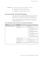
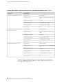
Table 12: Optical Interface Support for SFP Transceivers in EX 3200 and
EX 4200 Switches ...................................................................................21
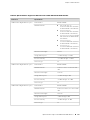
Table 13: Optical Interface Support for XFP Transceivers in EX 3200 and
EX 4200 Switches ...................................................................................23
Table 14: Copper Interface Support for SFP Transceivers in EX 3200 and
EX 4200 Switches ...................................................................................24
Table 15: EX-series Switch—LCD Menu Options ...........................................25
Table 16: Minimum Power Requirements for an EX 3200 Switch .................29
Table 17: Minimum Power Requirements for an EX 4200 Switch .................29
Table 18: AC Power Supply LEDs in EX 3200 and EX 4200 Switches ............30
Table 19: DC Power Supply LEDs in EX 3200 and EX 4200 Switches ............32
Table 20: Console Port Connector Pinout Information ...................................34
Table 21: Management Port Connector Pinout Information ..........................35
Table 22: Uplink Modules Connector Pinout Information ..............................35
Table 23: Virtual Chassis Ports Connector Pinout Information .......................42
Table 24: Site Preparation Checklist ..............................................................49
Table 25: Rack Requirements and Specifications for an EX-series Switch ......51
Table 26: EX-series Switches—External Dimensions .....................................51
Table 27: AC Power Supply Electrical Specifications for an EX-series
Switch .....................................................................................................54
Table 28: Site Electrical Wiring Guidelines .....................................................55
Table 29: AC Power Cord Specifications ........................................................56
Table 30: Inventory of Components Provided with an EX-series Switch ........63
List of Tables ■ xv

xvi ■ List of Tables
Complete Hardware Guide for EX 3200 and EX 4200 Switches

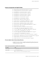
About This Topic Collection
■ How To Use This Guide on page xvii
■ List of EX-series Guides for JUNOS 9.2 on page xvii
■ Downloading Software on page xviii
■ Documentation Symbols Key on page xix
■ Documentation Feedback on page xx
■ Getting Support on page xx
How To Use This Guide
Complete documentation for the EX-series product family is provided on Web pages
at
http://www.juniper.net/techpubs/en_US/release-independent/information-products/pathway-pages/ex-series/product/index.html.
We have selected content from these Web pages and created a number of EX-series
guides that collect related topics into a book-like format so that the information is
easy to print and easy to download to your local computer.
This guide, Complete Hardware Guide for EX 3200 and EX 4200 Switches, collects
together information about the EX 3200 fixed-configuration and EX 4200
virtual-chassis switches. The release notes are at
http://www.juniper.net/techpubs/en_US/junos9.1/information-products/pathway-pages/ex-series/software/index.html.
List of EX-series Guides for JUNOS 9.2
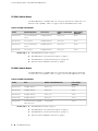
DescriptionTitle
Component descriptions, site preparation, installation, replacement,
and safety and compliance
Complete Hardware Guide for EX 3200 and EX 4200
Switches
Software feature descriptions, configuration examples and tasks, and
reference pages for configuration statements and operational
commands
Complete Software Guide for JUNOS Software for
EX-series Switches, Release 9.2
How to use the J-Web graphical user interface (GUI) with JUNOS
Software for EX-series Switches
J-Web User Interface Guide for JUNOS Software for
EX-series Switches
Summary of hardware and software features and known problems
with the software and hardware
JUNOS Software for EX-series Switches Release Notes,
Release 9.2
How To Use This Guide ■ xvii

Downloading Software
You can download the JUNOS software for EX-series switches from the Download
Software area at http://www.juniper.net/customers/support/. To download the software,
you must have a Juniper Networks user account. For information about obtaining an
account, see http://www.juniper.net/entitlement/setupAccountInfo.do.
xviii ■ Downloading Software
Complete Hardware Guide for EX 3200 and EX 4200 Switches

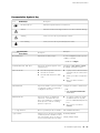
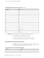
Documentation Symbols Key
Notice Icons DescriptionMeaningIcon
Indicates important features or instructions.Informational note
Indicates a situation that might result in loss of data or hardware damage.Caution
Alerts you to the risk of personal injury or death.Warning
Alerts you to the risk of personal injury from a laser.Laser warning
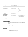
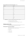
Text and Syntax
Conventions
Examples
DescriptionConvention
To enter configuration mode, type the
configure command:
user@host> configure
Represents text that you type.
Bold text like this
user@host> show chassis alarms
No alarms currently active
Represents output that appears on the
terminal screen.
Fixed-width text like this
■ A policy term is a named structure
that defines match conditions and
actions.
■ JUNOS System Basics Configuration
Guide
■ RFC 1997, BGP Communities
Attribute
■ Introduces important new terms.
■ Identifies book names.
■ Identifies RFC and Internet draft
titles.
Italic text like this
Configure the machine’s domain name:
[edit]
root@# set system domain-name
domain-name
Represents variables (options for which
you substitute a value) in commands or
configuration statements.
Italic text like this
■ To configure a stub area, include
the stub statement at the [edit
protocols ospf area area-id] hierarchy
level.
■ The console port is labeled
CONSOLE.
Represents names of configuration
statements, commands, files, and
directories; IP addresses; configuration
hierarchy levels; or labels on routing
platform components.
Plain text like this
stub <default-metric metric>;
Enclose optional keywords or variables.< > (angle brackets)
broadcast | multicast
(string1 | string2 | string3)
Indicates a choice between the mutually
exclusive keywords or variables on either
side of the symbol. The set of choices is
often enclosed in parentheses for clarity.
| (pipe symbol)
Documentation Symbols Key ■ xix
About This Topic Collection

# (pound sign)
rsvp { # Required for dynamic MPLS only
Indicates a comment specified on the
same line as the configuration statement
to which it applies.
community name members [ community-ids
]
Enclose a variable for which you can
substitute one or more values.
[ ] (square brackets)
[edit]
routing-options {
static {
route default {
nexthop address;
retain;
}
}
}
Identify a level in the configuration
hierarchy.
Indention and braces ( { } )
Identifies a leaf statement at a
configuration hierarchy level.
; (semicolon)
J-Web GUI Conventions
■ In the Logical Interfaces box, select
All Interfaces.
■ To cancel the configuration, click
Cancel.
Represents J-Web graphical user
interface (GUI) items you click or select.
Bold text like this
In the configuration editor hierarchy,
select Protocols>Ospf.
Separates levels in a hierarchy of J-Web
selections.
> (bold right angle bracket)
Documentation Feedback
We encourage you to provide feedback, comments, and suggestions so that we can
improve the documentation. Send email to [email protected] with the
following:
■ Document URL or title
■ Page number if applicable
■ Software version
■ Your name and company
Getting Support
For technical support, open a Case with JTAC on the Web or by telephone.
■
Case Manager at CSC: http://www.juniper.net/cm/
■ +1-888-314-JTAC (+1-888-314-5822, toll free in U.S., Canada, and Mexico)
xx ■ Documentation Feedback
Complete Hardware Guide for EX 3200 and EX 4200 Switches
La pagina si sta caricando...
La pagina si sta caricando...
La pagina si sta caricando...
La pagina si sta caricando...
La pagina si sta caricando...
La pagina si sta caricando...
La pagina si sta caricando...
La pagina si sta caricando...
La pagina si sta caricando...
La pagina si sta caricando...
La pagina si sta caricando...
La pagina si sta caricando...
La pagina si sta caricando...
La pagina si sta caricando...
La pagina si sta caricando...
La pagina si sta caricando...
La pagina si sta caricando...
La pagina si sta caricando...
La pagina si sta caricando...
La pagina si sta caricando...
La pagina si sta caricando...
La pagina si sta caricando...
La pagina si sta caricando...
La pagina si sta caricando...
La pagina si sta caricando...
La pagina si sta caricando...
La pagina si sta caricando...
La pagina si sta caricando...
La pagina si sta caricando...
La pagina si sta caricando...
La pagina si sta caricando...
La pagina si sta caricando...
La pagina si sta caricando...
La pagina si sta caricando...
La pagina si sta caricando...
La pagina si sta caricando...
La pagina si sta caricando...
La pagina si sta caricando...
La pagina si sta caricando...
La pagina si sta caricando...
La pagina si sta caricando...
La pagina si sta caricando...
La pagina si sta caricando...
La pagina si sta caricando...
La pagina si sta caricando...
La pagina si sta caricando...
La pagina si sta caricando...
La pagina si sta caricando...
La pagina si sta caricando...
La pagina si sta caricando...
La pagina si sta caricando...
La pagina si sta caricando...
La pagina si sta caricando...
La pagina si sta caricando...
La pagina si sta caricando...
La pagina si sta caricando...
La pagina si sta caricando...
La pagina si sta caricando...
La pagina si sta caricando...
La pagina si sta caricando...
La pagina si sta caricando...
La pagina si sta caricando...
La pagina si sta caricando...
La pagina si sta caricando...
La pagina si sta caricando...
La pagina si sta caricando...
La pagina si sta caricando...
La pagina si sta caricando...
La pagina si sta caricando...
La pagina si sta caricando...
La pagina si sta caricando...
La pagina si sta caricando...
La pagina si sta caricando...
La pagina si sta caricando...
La pagina si sta caricando...
La pagina si sta caricando...
La pagina si sta caricando...
La pagina si sta caricando...
La pagina si sta caricando...
La pagina si sta caricando...
La pagina si sta caricando...
La pagina si sta caricando...
La pagina si sta caricando...
La pagina si sta caricando...
La pagina si sta caricando...
La pagina si sta caricando...
La pagina si sta caricando...
La pagina si sta caricando...
La pagina si sta caricando...
La pagina si sta caricando...
La pagina si sta caricando...
La pagina si sta caricando...
La pagina si sta caricando...
La pagina si sta caricando...
La pagina si sta caricando...
La pagina si sta caricando...
La pagina si sta caricando...
La pagina si sta caricando...
La pagina si sta caricando...
La pagina si sta caricando...
La pagina si sta caricando...
La pagina si sta caricando...
La pagina si sta caricando...
La pagina si sta caricando...
La pagina si sta caricando...
La pagina si sta caricando...
La pagina si sta caricando...
La pagina si sta caricando...
La pagina si sta caricando...
La pagina si sta caricando...
La pagina si sta caricando...
La pagina si sta caricando...
La pagina si sta caricando...
La pagina si sta caricando...
La pagina si sta caricando...
La pagina si sta caricando...
La pagina si sta caricando...
La pagina si sta caricando...
La pagina si sta caricando...
La pagina si sta caricando...
La pagina si sta caricando...
La pagina si sta caricando...
La pagina si sta caricando...
La pagina si sta caricando...
La pagina si sta caricando...
La pagina si sta caricando...
La pagina si sta caricando...
La pagina si sta caricando...
La pagina si sta caricando...
La pagina si sta caricando...
La pagina si sta caricando...
La pagina si sta caricando...
La pagina si sta caricando...
La pagina si sta caricando...
La pagina si sta caricando...
La pagina si sta caricando...
La pagina si sta caricando...
La pagina si sta caricando...
La pagina si sta caricando...
La pagina si sta caricando...
La pagina si sta caricando...
La pagina si sta caricando...
La pagina si sta caricando...
La pagina si sta caricando...
La pagina si sta caricando...
La pagina si sta caricando...
La pagina si sta caricando...
La pagina si sta caricando...
La pagina si sta caricando...
La pagina si sta caricando...
La pagina si sta caricando...
La pagina si sta caricando...
La pagina si sta caricando...
La pagina si sta caricando...
La pagina si sta caricando...
La pagina si sta caricando...
La pagina si sta caricando...
La pagina si sta caricando...
La pagina si sta caricando...
La pagina si sta caricando...
La pagina si sta caricando...
La pagina si sta caricando...
La pagina si sta caricando...
La pagina si sta caricando...
La pagina si sta caricando...
La pagina si sta caricando...
La pagina si sta caricando...
La pagina si sta caricando...
La pagina si sta caricando...
La pagina si sta caricando...
La pagina si sta caricando...
La pagina si sta caricando...
La pagina si sta caricando...
La pagina si sta caricando...
-
 1
1
-
 2
2
-
 3
3
-
 4
4
-
 5
5
-
 6
6
-
 7
7
-
 8
8
-
 9
9
-
 10
10
-
 11
11
-
 12
12
-
 13
13
-
 14
14
-
 15
15
-
 16
16
-
 17
17
-
 18
18
-
 19
19
-
 20
20
-
 21
21
-
 22
22
-
 23
23
-
 24
24
-
 25
25
-
 26
26
-
 27
27
-
 28
28
-
 29
29
-
 30
30
-
 31
31
-
 32
32
-
 33
33
-
 34
34
-
 35
35
-
 36
36
-
 37
37
-
 38
38
-
 39
39
-
 40
40
-
 41
41
-
 42
42
-
 43
43
-
 44
44
-
 45
45
-
 46
46
-
 47
47
-
 48
48
-
 49
49
-
 50
50
-
 51
51
-
 52
52
-
 53
53
-
 54
54
-
 55
55
-
 56
56
-
 57
57
-
 58
58
-
 59
59
-
 60
60
-
 61
61
-
 62
62
-
 63
63
-
 64
64
-
 65
65
-
 66
66
-
 67
67
-
 68
68
-
 69
69
-
 70
70
-
 71
71
-
 72
72
-
 73
73
-
 74
74
-
 75
75
-
 76
76
-
 77
77
-
 78
78
-
 79
79
-
 80
80
-
 81
81
-
 82
82
-
 83
83
-
 84
84
-
 85
85
-
 86
86
-
 87
87
-
 88
88
-
 89
89
-
 90
90
-
 91
91
-
 92
92
-
 93
93
-
 94
94
-
 95
95
-
 96
96
-
 97
97
-
 98
98
-
 99
99
-
 100
100
-
 101
101
-
 102
102
-
 103
103
-
 104
104
-
 105
105
-
 106
106
-
 107
107
-
 108
108
-
 109
109
-
 110
110
-
 111
111
-
 112
112
-
 113
113
-
 114
114
-
 115
115
-
 116
116
-
 117
117
-
 118
118
-
 119
119
-
 120
120
-
 121
121
-
 122
122
-
 123
123
-
 124
124
-
 125
125
-
 126
126
-
 127
127
-
 128
128
-
 129
129
-
 130
130
-
 131
131
-
 132
132
-
 133
133
-
 134
134
-
 135
135
-
 136
136
-
 137
137
-
 138
138
-
 139
139
-
 140
140
-
 141
141
-
 142
142
-
 143
143
-
 144
144
-
 145
145
-
 146
146
-
 147
147
-
 148
148
-
 149
149
-
 150
150
-
 151
151
-
 152
152
-
 153
153
-
 154
154
-
 155
155
-
 156
156
-
 157
157
-
 158
158
-
 159
159
-
 160
160
-
 161
161
-
 162
162
-
 163
163
-
 164
164
-
 165
165
-
 166
166
-
 167
167
-
 168
168
-
 169
169
-
 170
170
-
 171
171
-
 172
172
-
 173
173
-
 174
174
-
 175
175
-
 176
176
-
 177
177
-
 178
178
-
 179
179
-
 180
180
-
 181
181
-
 182
182
-
 183
183
-
 184
184
-
 185
185
-
 186
186
-
 187
187
-
 188
188
-
 189
189
-
 190
190
-
 191
191
-
 192
192
-
 193
193
-
 194
194


Juniper Ex SERIES Complete Hardware Manual
- Categoria
- Switch di rete
- Tipo
- Complete Hardware Manual
in altre lingue
- English: Juniper Ex SERIES
Documenti correlati
-
Juniper JCS1200 Manuale utente
-
-
Juniper EX2300-C Manuale utente
-
-
Juniper QFX5120-48Y-AFI2 Manuale utente
-
-
-
-
-
Altri documenti
-
Quantum Scalar Key Manager Manuale utente
-
Grandstream GWN7816(P) Guida d'installazione
-
 AmazonBasics B07ZTQY9DD Manuale utente
-
Yamaha SFP-SWRG-SX Manuale del proprietario
-
 AmazonBasics B07RK3VP7W Manuale utente
-
Whirlwind edesk Guida utente
-
Add-On Computer Peripherals (ACP) GLC-FE-100LX-RGD-AO Scheda dati
-
i-PRO i-PRO WV-S71300-F3 Network Camera Manuale utente
-
-
Dell PowerStore Rack Guida Rapida

