Philips Fisio 311 Guida utente
- Categoria
- Cellulari
- Tipo
- Guida utente

Départ. Technical support- CM640 PROCEDURE COMPANY RESTRICTED
PHILIPS Consumer
Communications
Centre du Mans
Service Repair Support
VY-V-640-204
Page : 1 of 42
Langue : EN
Date : 09/21/01
PHILIPS ELECTRONICS N.V. 1999 by Toko ([email protected])
All rights reserved. Reproduction in whole
or in part is prohibited without the written
consent of the copyright owner.
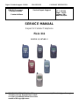
SERVICE MANUAL
Repair for Cellular Telephone
Fisio 311
LEVEL 1 / LEVEL 2

Départ. Technical support- CM640 PROCEDURE COMPANY RESTRICTED
PHILIPS Consumer
Communications
Centre du Mans
Service Repair Support
VY-V-640-204
Page : 2 of 42
Langue : EN
Date : 09/21/01
PHILIPS ELECTRONICS N.V. 1999 VY-V-640-204
All rights reserved. Reproduction in whole
or in part is prohibited without the written
consent of the copyright owner.
SERVICE Manual
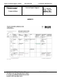
Last updates :
DATE MODIFICATION PAGE
07/09/00 REVISION 1
REVISION 2 : 21/09/01
Code Nomenclature suppressed
N° 4311 256 03841 : Sticker Process
Page : 39

Départ. Technical support- CM640 PROCEDURE COMPANY RESTRICTED
PHILIPS Consumer
Communications
Centre du Mans
Service Repair Support
VY-V-640-204
Page : 3 of 42
Langue : EN
Date : 09/21/01
PHILIPS ELECTRONICS N.V. 1999 VY-V-640-204
All rights reserved. Reproduction in whole
or in part is prohibited without the written
consent of the copyright owner.
CONTENTS
1.0 PURPOSE..............................................................................................................................................................................................4
2.0 SCOPE....................................................................................................................................................................................................4
3.0 REFERENCE........................................................................................................................................................................................4
4.0 GLOSSARY/ACRONYM LIST......................................................................................................................................................4
5.0 TEST EQUIPMENT AND TOOLS ...............................................................................................................................................4
6.0 TEST AND INPECTION PLAN.....................................................................................................................................................5
6.1 User Interface Test............................................................................................................................................................................5
6.2 RF Test................................................................................................................................................................................................5
7.0 BEFORE STARTING........................................................................................................................................................................6
7.1 Description Of The Transceiver.....................................................................................................................................................6
7.2 Description Of The Display.............................................................................................................................................................7
7.3 Using The Carousel..........................................................................................................................................................................8
7.4 Inserting The MICRO-Card.............................................................................................................................................................9
7.5 Inserting The Battery........................................................................................................................................................................9
7.6 Attach The Battery Cover................................................................................................................................................................9
7.7 Removing The Battery ...................................................................................................................................................................10
7.8 Charging The Battery .....................................................................................................................................................................10
7.9 W@P Introduction..........................................................................................................................................................................11
8.0 TEST PROCEDURES......................................................................................................................................................................13
8.1 Initial Functional Check for Fisio 311.........................................................................................................................................13
8.2 RF Test..............................................................................................................................................................................................16
8.3 Battery Charging (IGN : Ignition) / Current Consumption......................................................................................................20
8.4 W@P Test Procedure .....................................................................................................................................................................22
9.0 ASSEMBLY / DISMANTLEMENT PROCEDURES.............................................................................................................28
9.1 Dismantlement.................................................................................................................................................................................28
9.2 Assembly ..........................................................................................................................................................................................32
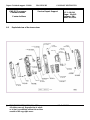
9.3 Exploded view of the transceiver.................................................................................................................................................36
10.0 SOLUTIONS IN CASE OF PROBLEMS DURING THE TESTS......................................................................................37
11.0 RECOMENDED PART LIST CT2888 FISIO311.................................................................................................................39
11.1 Common Parts - Out Of Warranty...............................................................................................................................................39
11.2 Specific Parts - Out Of Warranty.................................................................................................................................................40
11.3 Common parts – in warranty.........................................................................................................................................................41
ANNEX 1...........................................................................................................................................................................................................42

Départ. Technical support- CM640 PROCEDURE COMPANY RESTRICTED
PHILIPS Consumer
Communications
Centre du Mans
Service Repair Support
VY-V-640-204
Page : 4 of 42
Langue : EN
Date : 09/21/01
PHILIPS ELECTRONICS N.V. 1999 VY-V-640-204
All rights reserved. Reproduction in whole
or in part is prohibited without the written
consent of the copyright owner.
1.0 PURPOSE
This document establishes the functional test and inspection procedures for the first level service repair of the
FISIO 311 transceiver.
2.0 SCOPE
The test plan is applicable to all levels of service repair of the FISIO 311 transceiver.
3.0 REFERENCE
None.
4.0 GLOSSARY/ACRONYM LIST
Window or Bezzel Protective plastic over the LCD display
SW Software
PN Hardware Configuration of the Mobile
CN Matrix for Types of SW used on the different hardware
HW Hardware
ASC Authorized Service Center
NSC National Service Center
Test SIM Card Used for functionality of PHILIPS Mobile Phones
Test SIM Card « SP » SIM Card used to simulate the user interface and enable radio tests
5.0 TEST EQUIPMENT AND TOOLS
Equipment / Tools
- Production Test SIM Card - Part No. : 4311 255 00781
- Test SIM Card « SP » - Part No. : 4311 255 00782
- Digital Multimeter - Recommended Model : Fluke
Specification with current reading in mA.
- Digital Radiocommunication Tester.
- Coupling system with shielded chamber.
Or
- RF Cable - Part No.: 941-555-1(AMP)
(No mechanical adaptation provided by Philips.)

Départ. Technical support- CM640 PROCEDURE COMPANY RESTRICTED
PHILIPS Consumer
Communications
Centre du Mans
Service Repair Support
VY-V-640-204
Page : 5 of 42
Langue : EN
Date : 09/21/01
PHILIPS ELECTRONICS N.V. 1999 VY-V-640-204
All rights reserved. Reproduction in whole
or in part is prohibited without the written
consent of the copyright owner.
6.0 TEST AND INPECTION PLAN
The test plan is derived from the Product Test Reference of FISIO 311.
6.1 User Interface Test
Use the Test SIM Card « SP »/ Production to test the transceivers as follows :
• On/Off button
• LCD Backlight
• Keyboard Test
• Buzzer Test
• Vibrator Test
• Audio Test
• Antenna Test ( to measure the radiated power level. Not necessary when using an antenna coupler)
• LCD
• IMEI
• Tester Status/Eeprom Status
With a fast Charger connected with the PRODUCT’s bottom connector , check the full scrolling from one mode to
the next when charging IGN (Ignition) – Battery.
6.2 RF Test
The radio test must be performed with a Digital Radio Test Set. The mobile has to be set on the antenna coupler
inside the shielded chamber.

Départ. Technical support- CM640 PROCEDURE COMPANY RESTRICTED
PHILIPS Consumer
Communications
Centre du Mans
Service Repair Support
VY-V-640-204
Page : 6 of 42
Langue : EN
Date : 09/21/01
PHILIPS ELECTRONICS N.V. 1999 VY-V-640-204
All rights reserved. Reproduction in whole
or in part is prohibited without the written
consent of the copyright owner.
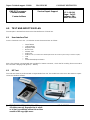
7.0 BEFORE STARTING
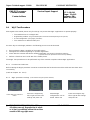
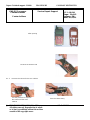
7.1 Description Of The Transceiver

Départ. Technical support- CM640 PROCEDURE COMPANY RESTRICTED
PHILIPS Consumer
Communications
Centre du Mans
Service Repair Support
VY-V-640-204
Page : 7 of 42
Langue : EN
Date : 09/21/01
PHILIPS ELECTRONICS N.V. 1999 VY-V-640-204
All rights reserved. Reproduction in whole
or in part is prohibited without the written
consent of the copyright owner.
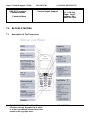
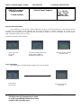
7.2 Description Of The Display

Départ. Technical support- CM640 PROCEDURE COMPANY RESTRICTED
PHILIPS Consumer
Communications
Centre du Mans
Service Repair Support
VY-V-640-204
Page : 8 of 42
Langue : EN
Date : 09/21/01
PHILIPS ELECTRONICS N.V. 1999 VY-V-640-204
All rights reserved. Reproduction in whole
or in part is prohibited without the written
consent of the copyright owner.
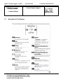
7.3 Using The Carousel
The carousel is a circular loop of icons displayed on the screen. These icons provide access to the different menus
and sub menus used to operate your phone.

Départ. Technical support- CM640 PROCEDURE COMPANY RESTRICTED
PHILIPS Consumer
Communications
Centre du Mans
Service Repair Support
VY-V-640-204
Page : 9 of 42
Langue : EN
Date : 09/21/01
PHILIPS ELECTRONICS N.V. 1999 VY-V-640-204
All rights reserved. Reproduction in whole
or in part is prohibited without the written
consent of the copyright owner.
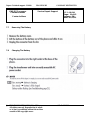
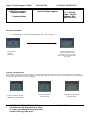
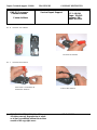
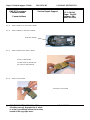
7.4 Inserting The MICRO-Card
7.5 Inserting The Battery
7.6 Attach The Battery Cover

Départ. Technical support- CM640 PROCEDURE COMPANY RESTRICTED
PHILIPS Consumer
Communications
Centre du Mans
Service Repair Support
VY-V-640-204
Page : 10 of 42
Langue : EN
Date : 09/21/01
PHILIPS ELECTRONICS N.V. 1999 VY-V-640-204
All rights reserved. Reproduction in whole
or in part is prohibited without the written
consent of the copyright owner.
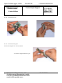
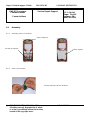
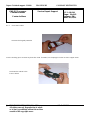
7.7 Removing The Battery
7.8 Charging The Battery

Départ. Technical support- CM640 PROCEDURE COMPANY RESTRICTED
PHILIPS Consumer
Communications
Centre du Mans
Service Repair Support
VY-V-640-204
Page : 11 of 42
Langue : EN
Date : 09/21/01
PHILIPS ELECTRONICS N.V. 1999 VY-V-640-204
All rights reserved. Reproduction in whole
or in part is prohibited without the written
consent of the copyright owner.
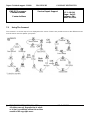
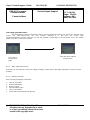
7.9 W@P Introduction
The purpose of W@p (Wireless Application Protocol) is to enable easy and fast delivery of relevant information and
services to mobile users. However, mobile Internet does not mean navigating on the Internet with a wireless device
but rather to access to some services in a mobile context.
The W@P architecture was designed to enable standard Internet servers to provide services to wireless devices.
The W@P wireless protocol is based on Internet standards such as HTTP and TLS but has been optimized
according to the constraints of the wireless terminals: low memory capacity, small screen size
and of the network: limited bandwidth.
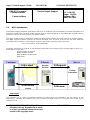
The W@P architecture is made up of 4 technological parts which are necessary for accessing W@P services on a
mobile phone. These are:
W@P navigator or browser
Mobile operator network
W@P gateway / W@P server
Web server
* Subscription
The customer has to contact his Network Operator to inquire about his subscription and the options he can
subscribe to. Generally the customer just have to request his W@P access to his provider and he will not be
charged for that.
Customer Gateway Server
1.0 Encoded
Request
2.0 Request
3.0 Answer
4.0 Encoded
Answer
Content
Generation
Encoder/
Decoder

Départ. Technical support- CM640 PROCEDURE COMPANY RESTRICTED
PHILIPS Consumer
Communications
Centre du Mans
Service Repair Support
VY-V-640-204
Page : 12 of 42
Langue : EN
Date : 09/21/01
PHILIPS ELECTRONICS N.V. 1999 VY-V-640-204
All rights reserved. Reproduction in whole
or in part is prohibited without the written
consent of the copyright owner.
* W@P parameters
Parameters have to be set in the mobile phone in order to access W@P services . However, there are two
cases depending on the commercial offer:
* Transceiver sold via an operator package(with subscription included):
- Parameters cannot be accessed from the W@P settings menu of the mobile phone:
The transceiver is W@P locked. The W@P connections will always be made from the
operator W@P homepage and search engines will be available. The customer will have to
ask for a password from his/her operator to unlock the W@P settings.
- Parameters can be accessed from the W@P settings menu of the mobile
phone:
The customer changes the W@P parameters according to his/her own convenience.
* Retail transceiver(without subscription included):
- Phones are configured by the manufacturer with no W@P parameter. The end user has
to ensure that the W@P functionalities and a data/fax options have been subscribed.
The end user has also to set the W@P parameters by asking for them from
his/her operator or by using parameters of another company (available on
Internet, newspaper etc.)
Detailed parameters
Phone Number (or dial-up number) : to establish a connection with the Internet Service Provider
Login (or User Name) : if requested by your ISP
The password : if requested by your ISP
IP address for the Gateway : for communications between Internet Service Provider and Gateway
& Port Number (for a secure or non secure connection)
Home page address(or URL address): for communications between Gateway and Web server
Please note that it is important to respect small and capital letters according to your operator instructions.
It is also possible that your provider does not require the Login and/or Password.

Départ. Technical support- CM640 PROCEDURE COMPANY RESTRICTED
PHILIPS Consumer
Communications
Centre du Mans
Service Repair Support
VY-V-640-204
Page : 13 of 42
Langue : EN
Date : 09/21/01
PHILIPS ELECTRONICS N.V. 1999 VY-V-640-204
All rights reserved. Reproduction in whole
or in part is prohibited without the written
consent of the copyright owner.
8.0 TEST PROCEDURES
8.1 Initial Functional Check for Fisio 311
8.1.1 Insert the Test Production Card into the SIM Reader at the back of the cellular phone and clip a charged
battery on the phone.
8.1.2 Press the «ON» button for 2 seconds at least and the LCD will show a message which contains information
of FA (Final Adjustment) status and 12NC.
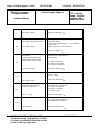
8.1.3 Follow the instructions as mentioned below :
Step Procedure Observation
1
Press Key 1
Press Key 1 again.
Continue Buzzer signal
Left corner displays 1
00
2
Press key 2
(Audio loop local effect)
Press key 2 again
"LocalEffect"
" XX XX XX“
“ XX XX”
Left corner displays 2
01
3
Press key 3
Audio loop test (Speak to Mic
and listen echo from Speaker)
Press key 3 again
"AUDIO xx xx xx xx”
"EEP xx xx xxxx ”
Left corner displays 3
02
4
Press key 4
Check for the Backlight
function in the same time.
Press key 4 again
Backlight must be on
Left corner displays 4
03
5
Press Key 5
(Checkerboard test)
Press Key 5 again
Checkerboard 1 pixel on
Left corner displays 5
04
6
Press Key 6
(Inverted Checkerboard)
Press Key 6 again
Checkerboard 2 pixel on
Left corner displays 6
05

Départ. Technical support- CM640 PROCEDURE COMPANY RESTRICTED
PHILIPS Consumer
Communications
Centre du Mans
Service Repair Support
VY-V-640-204
Page : 14 of 42
Langue : EN
Date : 09/21/01
PHILIPS ELECTRONICS N.V. 1999 VY-V-640-204
All rights reserved. Reproduction in whole
or in part is prohibited without the written
consent of the copyright owner.
7
Press Key 7
Press key 7 again
All pixels are on
Left corner displays 7
06
8
Press key 8 (Eeprom Status)
Press Key 8 again
"EEPROM STAT”
H-XXXX-XX-XX(No Digit “1” or “2” allowed)
L-XXXX-XX-X
SimLk XXXXX (Sim lock Status)
Left corner display 8
07
9
Press Key 9 Product
information
Compare information with
label printed on back case
Press key 9 again
“PROD INFO”
“XXXXXXXXX” (PN Number)
“XXXXXXXX”
VY made in Le Mans
SA made in Singapore
EO made in Shenzhen
Left corner displays 9
08
10
Press key 0
Press key 0 again
“ADC MEASURES”
“XXXX XXXX”
“XXXX XXXX”
Left corner displays 0
09
11
Press * (IMEI Test)
Compare IMEI with label
printed on back case
Press * again
"IMEI TEST"
" XXXXXX/ 50 / XXXXXXX"
06 made in Singapore
50 made in Le-Mans
69 made in China
Left corner displays *
12
12
Press # (FA Status)
Press # again
"FA/12NC”
FA GOOD (Must be good) X
XXXXXXXXXXX (12NC)
Left corner displays #
13

Départ. Technical support- CM640 PROCEDURE COMPANY RESTRICTED
PHILIPS Consumer
Communications
Centre du Mans
Service Repair Support
VY-V-640-204
Page : 15 of 42
Langue : EN
Date : 09/21/01
PHILIPS ELECTRONICS N.V. 1999 VY-V-640-204
All rights reserved. Reproduction in whole
or in part is prohibited without the written
consent of the copyright owner.
13
Press C
Press C again
Key without Test
Left corner displays C
15
14
Press the Left arrowhead
(Melody Test) & vibrator
Press Left again
User Melody should be heard and vibrations
felt
Left corner displays 0C
15
Press the Right arrowhead
(Memory Test)
Press Right again
“MEMORY TEST”
“XXXXXXXX”
“XXXXXXXX”
“RAM OK”
Left corner displays 0D
16
Press OK
Press OK again
“PAGE”
“SELECTION”
“XX”
Left corner display K
0
E
17
Press @
Press @ again
Key without Test
Left corner display @
14
19
Press Green button
Press Green button again
“ MANUAL TEST”
“ GOOD “
Left corner displays
OF
20
Press Red button
Press Red button again
“ MANUAL TEST”
“ BAD “
Left corner displays
10
8.1.4 If any of these steps failed functional, please refer to Chapter 10.
8.1.5 Perform visual check on battery connectors, car kit connectors and casing. If corrosion or deform send to
NSC for repair.
8.1.1 If the product is good, it is considered as a NFF (No Fault Found) product.
All the NFF products must be directly returned to the customer.

Départ. Technical support- CM640 PROCEDURE COMPANY RESTRICTED
PHILIPS Consumer
Communications
Centre du Mans
Service Repair Support
VY-V-640-204
Page : 16 of 42
Langue : EN
Date : 09/21/01
PHILIPS ELECTRONICS N.V. 1999 VY-V-640-204
All rights reserved. Reproduction in whole
or in part is prohibited without the written
consent of the copyright owner.
8.2 RF Test
8.2.1 The Test SIM Card “SP” must be inserted in t he phone before starting the tests.
8.2.2 Set the equipment as shown on the picture in chapter 6.2
8.2.3 Set RF losses as following (tested with antenna coupler):
8.2.4 The following operations must be done:
- Synchronization/Registration
- Call set up from the mobile
- Voice loopback ( to check the sound quality)
- Call release
- Call set up from tester
- Call release from tester
8.2.5 The following parameters must be checked in TCH loop mode :
Emission parameters :
- Power level
- RMS phase error
- Peak phase error
- Frequency error
- Power ramping
- Timing Advance
Reception parameters :
- Rx level
- Rx quality
- BER (Byte Error Rate)
- FER (Frame Error Rate)
Generally the test sequences built inside the testers will be used to check the mobile. You must assess that the test
sequences limits comply with the standard specifications and defined test plan.
Channel RX TX Channel RX TX
900 MHz 63 5,0 5,2 1800 MHz 598 27,0 13,0
3 4,0 3,2 512 23,0 10,0
62 5,0 5,2 700 27,0 13,0
123 6,0 4,1 884 19,0 16,7

Départ. Technical support- CM640 PROCEDURE COMPANY RESTRICTED
PHILIPS Consumer
Communications
Centre du Mans
Service Repair Support
VY-V-640-204
Page : 17 of 42
Langue : EN
Date : 09/21/01
PHILIPS ELECTRONICS N.V. 1999 VY-V-640-204
All rights reserved. Reproduction in whole
or in part is prohibited without the written
consent of the copyright owner.
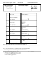
8.2.6 Radio test plan
Find below all the measurements which have to be done by test sequences.
M When using a wired test solution (via RF cable), don't forget that it is mandatory to measure the power level
radiated by the antenna (powermeter recommended). It is the only way to ensure good contact between
antenna and main board.
This warning doesn't apply when using an antenna coupler.
Synchronization/Registration To be checked
Call set up from the mobile To be checked
Voice loopback ( to check the sound quality) To be checked
Call release To be checked
Call set up from tester To be checked
Call release from tester To be checked
Dualband handover To be checked
Power level Measurements
Power level X X X X
RMS phase error X X X X
High level Peak phase error X X X X
Frequency error X X X X
Power ramping X X X X
Timing advance X X
Power level X X X X
RMS phase error
Mid level Peak phase error
Frequency error
Power ramping
Timing advance
Power level X X X X
RMS phase error
Low Level Peak phase error
Frequency error
Power ramping X X X X
Timing advance
RF Level Measurements
Rx level X X X X
Rx qual
BER
(Byte Error Rate)
X
X
X
X
FER
(Frame Error Rate)
Rx level X X X X
Rx qual X X X X
BER
(Byte Error Rate)
X
X
X
X
FER
(Frame Error Rate)
X
X
X
X
BER Measurements on 104 frames = 8200 bits minimum
TX measurements
GSM Channels
DCS Channels
-85.0 dBm
Low Mid High
RX measurements
DCS Channels
HighLow Mid
-102.0 dBm
Low Mid High
GSM Channels
Low Mid High

Départ. Technical support- CM640 PROCEDURE COMPANY RESTRICTED
PHILIPS Consumer
Communications
Centre du Mans
Service Repair Support
VY-V-640-204
Page : 18 of 42
Langue : EN
Date : 09/21/01
PHILIPS ELECTRONICS N.V. 1999 VY-V-640-204
All rights reserved. Reproduction in whole
or in part is prohibited without the written
consent of the copyright owner.
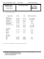
8.2.7 GSM Specification (900 Mhz)
Test parameter Channel Level Standard specifications
EMISSION
Phase Error RMS 1, 62, 124 5, 10, 15 0 to 5 degrees
Phase Error Peak 1, 62, 124 5, 10, 15 -20 to +20 degrees
Frequency Error 1, 62, 124 5, 10, 15 -90 Hz to +90 Hz
Power Ramping 1, 62, 124 5, 10, 15 Mask
Modulation 1, 62, 124 5, 10, 15 Mask
Switching Transients 1, 62, 124 5, 10, 15 Mask
Timing Advance 1, 62, 124 5, 10, 15 +/- 1.00 bit
Power Reading
Output Power Average 1, 62, 124 Level 19 5 +/- 5 dBm
1, 62, 124 Level 15 13 +/- 3 dBm
1, 62, 124 Level 10 23 +/- 2 dBm
1, 62, 124 Level 5 33 +/- 2 dBm
RECEPTION
Rx Level 1, 62, 124 -102 dBm 4 to 12
Rx Qual 0 to 1
Rx Level 1, 62, 124 -85 dBm 21 to 29
Rx Qual 0
Rx Level 1, 62, 124 -60 dBm 46 to 54
Rx Qual 0 to 0
TCH LOOP
SENSITIVITY
BER 1, 62, 124 -85 dBm 0%
FER 1, 62, 124 -85 dBm 0%
BER 1, 62, 124 -102 dBm < 2.44%
FER 1, 62, 124 -102 dBm 0%
If a phone is out of the specifications, it must be sent to the Repair Center.

Départ. Technical support- CM640 PROCEDURE COMPANY RESTRICTED
PHILIPS Consumer
Communications
Centre du Mans
Service Repair Support
VY-V-640-204
Page : 19 of 42
Langue : EN
Date : 09/21/01
PHILIPS ELECTRONICS N.V. 1999 VY-V-640-204
All rights reserved. Reproduction in whole
or in part is prohibited without the written
consent of the copyright owner.
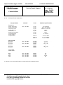
8.2.8 PCN Specification (1800 Mhz)
Test parameter Channel Level Standard specifications
ÉMISSION
Phase error RMS 512, 700, 885 0,5,10 0 to 5 degree
Phase error Peak 0,5,10 -20 to +20 degree
Frequency Error 0,5,10 -180 Hz to + 180 Hz
Power Ramping 0,5,10 Mask
Modulation 0,5,10 Mask
Switching Transients 0,5,10 Mask
Timing Advance 0,5,10 +/- 1.00 bit
Power reading
Output Power Level 0 30 +/- 2 dBm
Level 10 10 +/- 4.0 dBm
Level 15 0 +/- 5.0 dBm
RECEPTION
Rx Level 512, 700, 885 -102dbm 4 to 12
Rx Qual -102dbm 0 to 1
Rx Level 512, 700, 885 -85dbm 21 to 29
Rx Qual -85dbm 0
Rx Level 512, 700, 885 -60dbm 46 to 54
Rx Qual -60dbm 0
TCH LOOP
SENSITIVITY
BER 512, 700, 885 -85dbm 0%
FER 512, 700, 885 -85dbm 0%
BER 512, 700, 885 -102dbm 2.44%
FER 512, 700, 885 -102dbm 0%
If a phone is out of the specifications, it must be sent to the Repair Center.

Départ. Technical support- CM640 PROCEDURE COMPANY RESTRICTED
PHILIPS Consumer
Communications
Centre du Mans
Service Repair Support
VY-V-640-204
Page : 20 of 42
Langue : EN
Date : 09/21/01
PHILIPS ELECTRONICS N.V. 1999 VY-V-640-204
All rights reserved. Reproduction in whole
or in part is prohibited without the written
consent of the copyright owner.
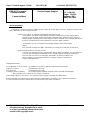
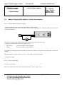
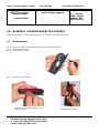
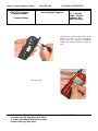
8.3 Battery Charging (IGN : Ignition) / Current Consumption
8.3.1 Charger detection / Battery charging
- Plug the transformer unit into an easily accessible AC power socket.
- Insert the Test production Card in the mobile, plug a reference Battery with a multimeter added (see picture) for
current measurement.
- Plug the connector of the charger into the right socket at the base of the transceiver
The battery symbol should indicate the state of charge :
• Bars moving - means the battery is being charged.
• Steady - means the battery is fully charged.
If the battery is totally discharged, the battery icon will start scrolling 2 to 3 minutes only after being connected to
charger.
After few seconds a charge current of 400 < I (mA) < 600 have to be observed
- Unplug the charger
8.3.2 Current consumption
a) Check current_OFF :
When the mobile is OFF the current measured must be : 0.05 < I (mA) < 0.23
La pagina si sta caricando...
La pagina si sta caricando...
La pagina si sta caricando...
La pagina si sta caricando...
La pagina si sta caricando...
La pagina si sta caricando...
La pagina si sta caricando...
La pagina si sta caricando...
La pagina si sta caricando...
La pagina si sta caricando...
La pagina si sta caricando...
La pagina si sta caricando...
La pagina si sta caricando...
La pagina si sta caricando...
La pagina si sta caricando...
La pagina si sta caricando...
La pagina si sta caricando...
La pagina si sta caricando...
La pagina si sta caricando...
La pagina si sta caricando...
La pagina si sta caricando...
La pagina si sta caricando...
-
 1
1
-
 2
2
-
 3
3
-
 4
4
-
 5
5
-
 6
6
-
 7
7
-
 8
8
-
 9
9
-
 10
10
-
 11
11
-
 12
12
-
 13
13
-
 14
14
-
 15
15
-
 16
16
-
 17
17
-
 18
18
-
 19
19
-
 20
20
-
 21
21
-
 22
22
-
 23
23
-
 24
24
-
 25
25
-
 26
26
-
 27
27
-
 28
28
-
 29
29
-
 30
30
-
 31
31
-
 32
32
-
 33
33
-
 34
34
-
 35
35
-
 36
36
-
 37
37
-
 38
38
-
 39
39
-
 40
40
-
 41
41
-
 42
42


Philips Fisio 311 Guida utente
- Categoria
- Cellulari
- Tipo
- Guida utente
in altre lingue
- English: Philips Fisio 311 User guide
Documenti correlati
-
Philips Fisio 120 Voice Manuale utente
-
-
Philips 32PFS6402/12 Manuale utente
-
-
Philips 107P50/97 Manuale utente
-
-
-
-
