Yamaha CS1D Manuale del proprietario
- Categoria
- Mixer audio
- Tipo
- Manuale del proprietario

Owner’s Manual

FCC INFORMATION (U.S.A.)
1. IMPORTANT NOTICE: DO NOT MODIFY THIS UNIT! This product, when installed as indicated in the instructions contained in this manual, meets FCC
requirements. Modifications not expressly approved by Yamaha may void your authority, granted by the FCC, to use the product.
2. IMPORTANT: When connecting this product to accessories and/or another product use only high quality shielded cables. Cable/s supplied with this product MUST
be used. Follow all installation instructions. Failure to follow instructions could void your FCC authorization to use this product in the USA.
3. NOTE: This product has been tested and found to comply with the requirements listed in FCC Regulations, Part 15 for Class “B” digital devices. Compliance with
these requirements provides a reasonable level of assurance that your use of this product in a residential environment will not result in harmful interference with
other electronic devices. This equipment generates/uses radio frequencies and, if not installed and used according to the instructions found in the users manual, may
cause interference harmful to the operation of other electronic devices. Compliance with FCC regulations does not guarantee that interference will not occur in all
installations. If this product is found to be the source of interference, which can be determined by turning the unit “OFF” and “ON”, please try to eliminate the
problem by using one of the following measures: Relocate either this product or the device that is being affected by the interference. Utilize power outlets that are on
different branch (circuit breaker or fuse) circuits or install AC line filter/s. In the case of radio or TV interference, relocate/reorient the antenna. If the antenna lead-in
is 300 ohm ribbon lead, change the lead-in to coaxial type cable. If these corrective measures do not produce satisfactory results, please contact the local retailer
authorized to distribute this type of product. If you can not locate the appropriate retailer, please contact Yamaha Corporation of America, Electronic Service
Division, 6600 Orangethorpe Ave, Buena Park, CA 90620
The above statements apply ONLY to those products distributed by Yamaha Corporation of America or its subsidiaries.
* This applies only to products distributed by YAMAHA CORPORATION OF AMERICA. (Perchlorate)
This product contains a battery that contains perchlorate material.
Perchlorate Material—special handling may apply,
See www.dtsc.ca.gov/hazardouswaste/perchlorate.
This product contains a high intensity lamp that
contains a small amount of mercury. Disposal of
this material may be regulated due to environmen-
tal considerations.
For disposal information in the United States, refer
to the Electronic Industries Alliance web site:
www.eiae.org
(mercury)* This applies only to products distributed by
YAMAHA CORPORATION OF AMERICA.
* This applies only to products distributed by
YAMAHA CORPORATION OF AMERICA.
COMPLIANCE INFORMATION STATEMENT
(DECLARATION OF CONFORMITY PROCEDURE)
Responsible Party : Yamaha Corporation of America
Address : 6600 Orangethorpe Ave., Buena Park, Calif. 90620
Telephone : 714-522-9011
Type of Equipment : Control Surface
Model Name : CS1D
This device complies with Part 15 of the FCC Rules.
Operation is subject to the following two conditions:
1) this device may not cause harmful interference, and
2) this device must accept any interference received including interference
that may cause undesired operation.
See user manual instructions if interference to radio reception is sus-
pected.
(FCC DoC)
NEDERLAND / THE NETHERLANDS
• Dit apparaat bevat een lithium batterij voor geheugen back-up.
• This apparatus contains a lithium battery for memory back-up.
• Raadpleeg uw leverancier over de verwijdering van de batterij
op het moment dat u het apparaat ann het einde van de lev-
ensduur of gelieve dan contact op te nemen met de vertegen-
woordiging van Yamaha in uw land.
•For the removal of the battery at the moment of the disposal at
the end of life please consult your retailer or Yamaha repre-
sentative office in your country.
• Gooi de batterij niet weg, maar lever hem in als KCA.
• Do not throw away the battery. Instead, hand it in as small
chemical waste.
(lithium disposal)
ADVARSEL!
Lithiumbatteri—Eksplosionsfare ved fejlagtig
håndtering. Udskiftning må kun ske med batteri
af samme fabrikat og type. Levér det brugte
batteri tilbage til leverandoren.
VARNING
Explosionsfara vid felaktigt batteribyte. Använd
samma batterityp eller en ekvivalent typ som
rekommenderas av apparattillverkaren.
Kassera använt batteri enligt fabrikantens
instruktion.
VAROITUS
Paristo voi räjähtää, jos se on virheellisesti
asennettu. Vaihda paristo ainoastaan
laitevalmistajan suosittelemaan tyyppiin. Hävitä
käytetty paristo valmistajan ohjeiden
mukaisesti.

ii
Important
Read the following before operating the CS1D
Warnings
•
Do not allow water to enter this unit or allow the unit
to become wet. Fire or electrical shock may result.
•
Connect this unit’s power cord only to an AC outlet of
the type stated in this Owner’s Manual or as marked
on the unit. Failure to do so is a fire and electrical
shock hazard.
•
Do not place heavy objects, including this unit, on top
of the power cord. A damaged power cord is a fire and
electrical shock hazard. In particular, be careful not to
place heavy objects on a power cord covered by a car-
pet.
•
Do not modify the unit. Doing so is a fire and electri-
cal shock hazard.
•
Do not place a container with liquid or small metal
objects on top of this unit. Liquid or metal objects
inside this unit are a fire and electrical shock hazard.
Cautions
•
This unit has ventilation holes at the top and bottom
to prevent the internal temperature rising too high.
Do not block them. Blocked ventilation holes are a fire
hazard.
•
Since this device is heavy, please use an appropriate
number of people (two or more) when moving it.
•
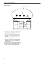
Before moving the CS1D, you must be sure to lower
the display toward the back until it is fastened in posi-
tion.
•
Do not use the device or headphones for a long period
of time at a high or uncomfortable volume level, since
this can cause permanent hearing loss. If you experi-
ence any hearing loss or ringing in the ears, consult a
physician.
•
Do not apply oil, grease, or contact cleaner to the fad-
ers. Doing so may cause problems with electrical con-
tact or fader motion.
Operating Notes
•
The digital circuits of this unit may induce a slight
noise into nearby radios and TVs. If noise occurs, relo-
cate the affected equipment.
•
Using a mobile telephone near this unit may induce
noise. If noise occurs, use the telephone away from the
unit.
•
XLR-type connectors are wired as follows: pin 1:
ground, pin 2: hot (+), and pin 3: cold (–).
•
If the message “WARNING LOW BATTERY !” appears
when you turn on this unit, contact your dealer as
soon as possible about replacing the internal data
backup battery. The unit will still operate correctly,
but data other than the presets will be lost.
We recommend that you save the data on an ATA-
compatible PC flash storage card before replacing the
battery.
•
The performance of components with moving con-
tacts, such switches, rotary controls, faders, fans, and
connectors, deteriorates over time. The rate of deterio-
ration depends on the operating environment and is
unavoidable. Consult your dealer about replacing
defective components.
•
The CS1D is cooled by fan exhaust openings located
on its rear panel. Check these regularly and use a vac-
uum cleaner etc. to ensure that the openings do not
become clogged with dust. Before performing this
maintenance, you must turn off the POWER switch of
the PM1D power supply unit and make sure that the
CS1D is not operating.
•
The power must be turned on/off using the POWER
switch of the PW1D power supply unit. Do not turn
the power on/off by plugging in the power cable, or by
using a power strip or circuit breaker. Doing so may
cause malfunctions.
•
Do not rapidly turn on and off the POWER switch of
the PW1D power supply unit. Doing so may cause
excessive current to damage the system. You must
allow at least five seconds to elapse between power-on
and power-off.
Handling the included PM1D System Software disc
The included PM1D System Software Disc is CD-R media containing documentation and software for the PM1D.
A computer with a connected CD drive is required in order to use this documentation and software.
For details on the contents, refer to the documentation on the disc.
Please observe the following points when handling the disc.
Failure to do so may cause problems such as the recorded data being lost, the drive to malfunction, or the printed label to
become blurred.
•
Do not place the disc in locations of direct sunlight,
high temperature, or high humidity.
•
Do not touch either surface of the disc.
Hold the disc at the edges. Gently wipe dust or dirt off
of the recording surface of the disc.

Important
iii
•
Do not wipe the disc with chemicals or detergents.
•
Do not bend or drop the disc.
•
Use an air duster or cleaner to remove dust. Vigorously
rubbing the surface of the disc with a dry cloth may
scratch the disc.
•
Do not write on the disc or affix labels to it.
•
Keep water droplets or condensation off of the label
surface.
•
Yamaha Corporation makes no guarantee of a disc
that is rendered unreadable due to careless handling.
CS1D Exclusion of Certain Responsibility
Manufacturer, importer, or dealer shall not be liable for any incidental damages including personal injury or any other
damages caused by improper use or operation of the CS1D.
About the LCD display
The LCD screen built into the CS1D has the following characteristics. Please be aware that even if the following symp-
toms occur, this is not a malfunction or a defect.
•
Since the LCD display is manufactured with extremely
delicate technology, individual pixels may not display
correctly. (A pixel may be constantly lit or constantly
dark.)
•
The LCD screen may be affected by changes in the
ambient temperature.
•
Depending on the environment of use, you may notice
unevenness in brightness or small spots.
•
Since the LCD screen uses a cold cathode tube for a
backlight, the state of the display will gradually change
over time.
Cautions when handling the track pad
•
Place your hand and arm in a relaxed, natural posi-
tion, and operate the track pad by moving your finger
lightly across the surface or tapping it gently.
•
This device is designed to be operated with one finger.
It will not operate in the following situations.
1) When operated by a gloved finger
2) When operated with a pen, ballpoint pen, or pen-
cil etc.
3) When operated by two or more fingers
4) When operated with an object placed on it
•
The unit may not operate correctly if water droplets or
condensation are present on the surface, or if operated
using a soiled or sweaty finger. If condensation occurs,
dry the unit thoroughly, or wipe it dry before use.
•
To avoid malfunctions, please observe the following
cautions.
1) Do not drop objects on the unit, strike it, or sub-
ject it to strong physical shock.
2) Do not spill coffee, juice, or other liquids on the
unit.
•
Do not operate the unit with a pointed metal object
such as a pen, since this will damage the unit.
•
If the surface becomes soiled, wipe it clean with a dry
cloth. If the surface is severely soiled, wipe with a
moist cloth, and dry carefully before use.
•
Do not touch the surface while the por is being turned
on.
Trademarks
ADAT MultiChannel Optical Digital Interface is a trademark and ADAT and Alesis are registered trademarks of Alesis
Corporation. Tascam Digital Interface is a trademark and Tascam and Teac are registered trademarks of Teac Corpora-
tion. Windows and Windows NT are trademarks of Microsoft Corporation. Compact Flash is a trademark of SanDisk
Corporation. Yamaha is a trademark of Yamaha Corporation. All other trademarks are the property of their respective
holders and are hereby acknowledged.
Copyright
No part of the CS1D software or this
Owner’s Manual
may be reproduced or distributed in any form or by any means
without the prior written authorization of Yamaha Corporation.
© 2000 Yamaha Corporation. All rights reserved.
Yamaha website
http://www.yamaha.co.jp/product/proaudio/homeenglish
Yamaha manual Library
http://www2.yamaha.co.jp/manual/english/

Operating Manual

Operating Manual
(Start-up)

ii
Contents
Introduction . . . . . . . . . . . . . . . . . . . . . . . . . . . . . . . . . . . . . . . . .1
About the “CS1D Operating Manual (Start-up)” . . . . . . . . . . . . . . . . . . . . . . . . . . 1
Printing conventions in “CS1D Operating Manual (Start-up)”. . . . . . . . . . . . . . . . 1
Introducing the various components . . . . . . . . . . . . . . . . . . . . .2
Terms used in the “CS1D Operating Manual (Start-up)” . . . . . . . . . . . . . . . . . . . . 4
Connections (Standard mode). . . . . . . . . . . . . . . . . . . . . . . . . . .6
Connecting the console and engine (Standard mode) . . . . . . . . . . . . . . . . . . . . . . 6
Connecting an analog input/output unit to the engine (Standard
mode) . . . . . . . . . . . . . . . . . . . . . . . . . . . . . . . . . . . . . . . . . . . . . . . . . . . . . . . . . . . . 8
Connecting a digital input/output unit to the engine (Standard mode) . . . . . . . . 9
Connections (Mirror mode). . . . . . . . . . . . . . . . . . . . . . . . . . . .10
Connecting the console and engines (Mirror mode) . . . . . . . . . . . . . . . . . . . . . . 10
Connecting an analog input/output unit to the engines (Mirror mode) . . . . . . . 12
Connecting a digital input/output unit to the engines (Mirror mode) . . . . . . . . 13
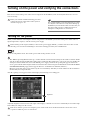
Turning on the power and verifying the connections . . . . . . .14
Turning on the power . . . . . . . . . . . . . . . . . . . . . . . . . . . . . . . . . . . . . . . . . . . . . . 14
Checking the status of each device (Standard mode). . . . . . . . . . . . . . . . . . . . . . 15
Checking the engine (Standard mode) . . . . . . . . . . . . . . . . . . . . . . . . . . . . . . 15
Checking the analog input unit (Standard mode) . . . . . . . . . . . . . . . . . . . . . . 16
Checking the analog output unit (Standard mode) . . . . . . . . . . . . . . . . . . . . . 17
Digital input/output unit (Standard mode) . . . . . . . . . . . . . . . . . . . . . . . . . . . 17
Checking the status of each device (Mirror mode) . . . . . . . . . . . . . . . . . . . . . . . . 18
Engines (Mirror mode) . . . . . . . . . . . . . . . . . . . . . . . . . . . . . . . . . . . . . . . . . . 18
Checking the analog input unit (Mirror mode) . . . . . . . . . . . . . . . . . . . . . . . . 19
Checking the analog output unit (Mirror mode) . . . . . . . . . . . . . . . . . . . . . . . 20
Checking the digital input/output unit (Mirror mode) . . . . . . . . . . . . . . . . . . . 21
Basic settings (Standard mode). . . . . . . . . . . . . . . . . . . . . . . . .22
Selecting the operation mode (Standard mode) . . . . . . . . . . . . . . . . . . . . . . . . . 22
Setting the word clock (Standard mode) . . . . . . . . . . . . . . . . . . . . . . . . . . . . . . . 24

Contents
iii
Basic settings (Mirror mode) . . . . . . . . . . . . . . . . . . . . . . . . . . 26
Selecting the operation mode (Mirror mode) . . . . . . . . . . . . . . . . . . . . . . . . . . . 26
Setting the word clock (Mirror mode) . . . . . . . . . . . . . . . . . . . . . . . . . . . . . . . . . 28
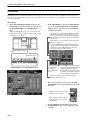
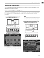
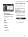
Checking the operation of input units . . . . . . . . . . . . . . . . . . . 30
Preparations for checking . . . . . . . . . . . . . . . . . . . . . . . . . . . . . . . . . . . . . . . . . . . 30
Connect the monitor system . . . . . . . . . . . . . . . . . . . . . . . . . . . . . . . . . . . . . . . . . 31
Connect an input source . . . . . . . . . . . . . . . . . . . . . . . . . . . . . . . . . . . . . . . . . . . . 32
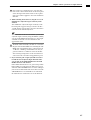
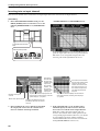
Patch the input unit to an input channel . . . . . . . . . . . . . . . . . . . . . . . . . . . . . . . 33
Monitor the input signal . . . . . . . . . . . . . . . . . . . . . . . . . . . . . . . . . . . . . . . . . . . . 36
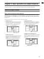
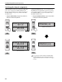
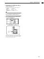
Checking the operation of an output unit . . . . . . . . . . . . . . . . 38
Preparations for checking . . . . . . . . . . . . . . . . . . . . . . . . . . . . . . . . . . . . . . . . . . . 38
Connect the monitor system . . . . . . . . . . . . . . . . . . . . . . . . . . . . . . . . . . . . . . . . . 39
Connect an input source . . . . . . . . . . . . . . . . . . . . . . . . . . . . . . . . . . . . . . . . . . . . 40
Patch the input unit to an input channel . . . . . . . . . . . . . . . . . . . . . . . . . . . . . . . 41
Patch the STEREO A channel to an output unit . . . . . . . . . . . . . . . . . . . . . . . . . . 42
Send the input signals of input channels 1/2 to the STEREO bus . . . . . . . . . . . . 44
Turn off the power. . . . . . . . . . . . . . . . . . . . . . . . . . . . . . . . . . . . . . . . . . . . . . . . . 46

1
Introduction
About the “CS1D Operating Manual (Start-up)”
The “CS1D Operating Manual (Start-up)” is an introductory manual that explains how to connect the various compo-
nents of the PM1D system and verify that the PM1D system is operating correctly.
When starting up the PM1D system for the first time, or if you have changed the configuration of the system such as
when the PM1D system has been moved to another location and/or re-connected, we recommend that you follow the
procedure described in this manual to verify that the system is operating correctly.
•
This manual explains only the minimum operations.
For details on operating the PM1D system, please
refer to “CS1D Operating Manual (Basic operation)”
•
For details on the specifications and functionality of
the engine (DSP unit DSP1D-EX {DSP1D}) and I/O
units, please refer to the owner’s manual included
with each device.
•
For details on the function and operation of the con-
trollers and connectors found on the top panel, rear
panel, and front panel of the console (CS1D), refer to
“CS1D Reference Manual (Hardware).”
•
For details on the software in the display screen of
the console (CS1D), refer to “CS1D Reference Man-
ual (Software).”
Screen shots shown in this manual are taken from a
prototype. Please be aware that they may differ
slightly from the actual screens on your unit.
Printing conventions in “CS1D Operating Manual (Start-up)”
•
Differences between the 96 channel model and 48
channel model
In general, the “CS1D Operating Manual (Start-up)”
is written with the 96 channel model PM1D system
(the model with the DSP1D-EX as the engine) in
mind. Where the functionality of the 96 channel
model differs from the 48 channel model (the model
with the DSP1D as the engine), the functionality of
the 48 channel model is enclosed in curly brackets { }.
•
Standard mode and Mirror mode
The PM1D system has two operation modes (ele-
ments that determine system structure and connec-
tion method); “Standard mode” in which one
console is connected to one engine, and “Mirror”
mode in which one console is connected to two
engines of which only one is used.
Be aware that the mode used by the PM1D system
will depend not only on the number of engines, but
also on the type of connections and on the internal
settings.
Explanations that apply only to
Standard mode
will
be indicated by the following symbol.
Explanations that apply only to
Mirror mode
will be
indicated by the following symbol.
The PM1D system version 1.0 does not support any
other operation mode (i.e., other than Mirror
mode) in which two engines are used.
•
Distinguishing between the controls of the CS1D
and the on-screen knobs/buttons
Names of controls (switches, encoders, faders) on the
top panel, rear panel, and front panel of the CS1D
are enclosed in square brackets [ ] in order to distin-
guish them from the knobs and buttons etc. that are
displayed in the screen.
Example
: Tu rn on the [TO ST] switch.
(This indicates an operation on the top panel of the
CS1D.)
Example
: Click the BASIC button.
(This indicates an operation in the display screen.)
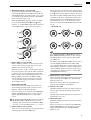
•
Va r ious icons
The following icon is used to call your attention to
various tips for operation or to reference pages.
The following icon is used to indicate particularly
important items or operations that you must be
aware of.
DSP
x1x1
DSP
x2x2
Hint

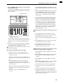
2
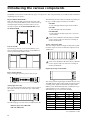
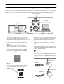
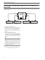
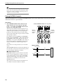
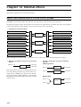
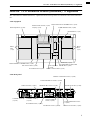
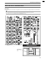
Introducing the various components
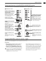
The PM1D system consists of the following types of components. (The components that are actually included will differ
depending on your system.)
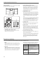
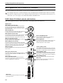
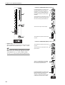
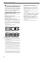
Engine (DSP1D-EX {DSP1D})
This is the DSP unit that performs the majority of the
audio processing in the PM1D system, such as audio sig-
nal input/output, mixing, and effects. There are two
models of engine: the
96 channel DSP1D-EX
, and the
48 channel DSP1D
.
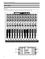
Console (CS1D)
The mixing operations, scene memory/library opera-
tions, and various editing operations of the PM1D sys-
tem are performed from this console.
Power supply (PW1D)
This power supply provides power to the console.
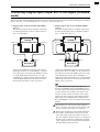
Analog input unit (AI8)
This is an input unit that inputs analog audio signals to
the engine, and can accommodate up to eight analog
input cards.
The following types of cards can be installed in the AI8.
•
Mic/line input card (LMY2-ML)
•
AD card (LMY4-AD)
The following models of AI8 are available, depending on
the type of analog input cards that are installed.
•
AI8-ML8
A unit with eight mic/line input cards installed
•
AI8-AD8
A unit with eight AD cards installed
•
AI8-ML4AD4
A unit with four mic/line input cards + four AD
cards installed
Cards can be installed in the AI8 only by a Yamaha
service engineer. The user must never attempt to
install a card himself.
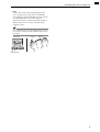
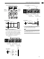
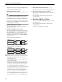
Analog output unit (AO8)
This is an output unit that outputs analog audio signals
from the engine, and can accommodate eight DA cards
(LMY4-DA).
Cards can be installed in the AO8 only by a Yamaha
service engineer. The user must never attempt to
install a card himself.
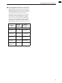
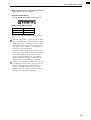
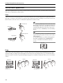
Digital input/output unit (DIO8)
This unit performs input/output of ADAT, Tascam, and
AES/EBU format digital audio signals and input/output
of analog audio signals to and from the engine of the
PM1D system. Each DIO8 unit can accommodate up to
eight digital I/O cards or analog I/O cards.
The following types of card can be installed.
POWER
ON/ OFF
A B
ENGINE ID
1 2
CONTROL I/O
48CH 96CH
INPUT
CONFIGURATION
POWER
ON OFF
INPUT UNIT NO.
PHANTOM MASTER
ON
OFF
+48V
POWER
ON/ OFF
12345678
ANALOG INPUT BOX
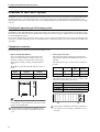
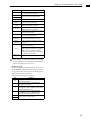
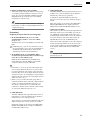
Card Format Input Output
MY8-TD TASCAM 8 IN 8 OUT
MY8-AT ADAT 8 IN 8 OUT
MY8-AE AES/EBU 8 IN 8 OUT
MY8-AD ANALOG IN 8 IN —
MY4-AD ANALOG IN 4 IN —
MY4-DA ANALOG OUT — 4 OUT
AP8AD* ANALOG IN 8 IN —
AP8DA*
*: Manufactured by Apogee Corporation
* As of September 1, 2000
ANALOG OUT — 8 OUT
1234567
OUTPUT UNIT NO.
INPUT SELECTOR
A
B
POWER
ON/ OFF
8
ANALOG OUTPUT BOX
I/O UNIT ID
PORT B SELECTOR
5-8
1-4
POWER
ON/ OFF

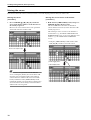
Introducing the various components
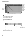
3
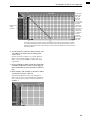
It is not possible to install and use a total of five or
more AP8AD/AP8DA cards. Also, if you are using
AP8AD/AP8DA cards simultaneously with MY8-
AD/MY4-AD/MY4-DA cards, there are restrictions
on the number of cards, as described below. Never
exceed the allowable number of cards, since
attempting to use a greater number of cards than
allowed may damage the DIO8 due to excessive
current. If you are not using AP8AD or AP8DA
cards, or if you are using AP8AD or AP8DA cards
simultaneously with an MY8-TD/MY8-AT/MY8-
AE card, there is no limitation on the number of
MY8-TD/MY8-AT/MY8-AE cards that can be used.
[AP8AD] +
[AP8DA] cards
used
[MY8-AD] +
[MY4-AD] +
[MY4-DA]
cards used
[MY8-TD] +
[MY8-AT] +
[MY8-AE] cards
used
Total 0 cards Up to a total of 8 cards
Total 1 card Up to 6 cards
Up to the number
of vacant DIO8
slots
Total 2 cards Up to 4 cards
Up to the number
of vacant DIO8
slots
Total 3 cards Up to 2 cards
Up to the number
of vacant DIO8
slots
Total 4 card Up to 1 card
Up to the number
of vacant DIO8
slots
Total 5 or more
cards cannot
be used
——

CS1D Operating Manual (Start-up)
4
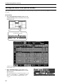
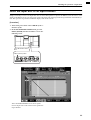
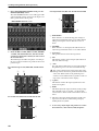
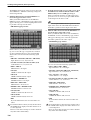
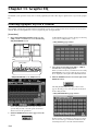
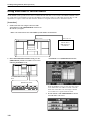
Terms used in the “CS1D Operating Manual (Start-up)”
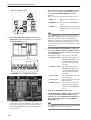
Of the specialized terms used in operating the CS1D, this section will explain the terms that appear in “CS1D Operating
Manual (Start-up).” For a more detailed explanation of terms, refer to “CS1D Operating Manual (Basic Operation).”
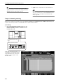
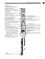
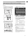
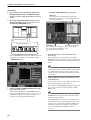
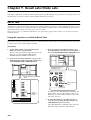
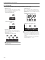
•
Display
This refers to the LCD display located in the upper
center of the CS1D console. When you wish to
change an internal setting of the CS1D, you can recall
the appropriate screen in the display, and use the
buttons or knobs in the display to edit the setting.
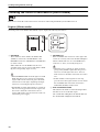
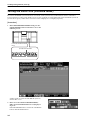
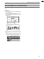
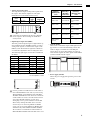
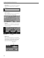
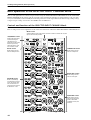
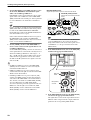
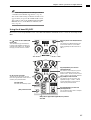
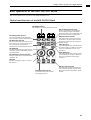
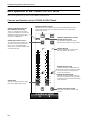
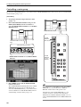
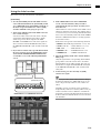
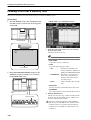
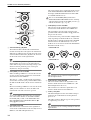
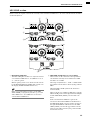
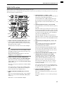
•
Pointer
The arrow shown in the display is called the
“pointer,” and is used to select the object that you
wish to modify. You can move the pointer by pressing
your finger on the track pad (located in the data
entry block) and dragging it up/down/left/right.
•
Cursor
The red frame shown in the display is called the “cur-
sor.” An on-screen item will be enclosed by the cur-
sor to indicate that this item is selected for
modification.
•
Click
“Click” refers to the action of placing the pointer on
a specific item in the display, and pressing the left or
right switch of the track pad (located in the data
entry block). This action is used to turn an on-screen
button on/off, or to move the cursor to a specific
item.
Using the [CURSOR] switches (located in the data
entry block) to move the cursor to a specific item and
then pressing the [ENTER] switch will have the same
result as clicking on that item.
Hint
As alternative ways to perform this action, you can
use a mouse connected to the MOUSE connector of
the CS1D, or use the arrow keys and ENTER key of a
keyboard connected to the KEYBOARD connector of
the CS1D.
[CURSOR] switches
Tra ck pad
Left switch[ENTER] switches
Display
Data entry block
Right switch
Pointer
Cursor
Left switch
Click
Mouse left click
Right switch
Click
Mouse right click

Introducing the various components
5
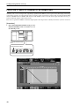
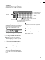
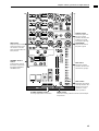
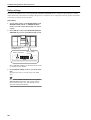
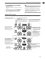
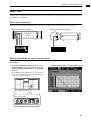
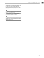
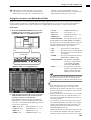
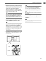
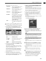
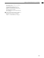
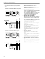
•
Drag
“Drag” refers to the action of placing the pointer
over a specific object on the screen, and holding
down the left or right switch while you slide your fin-
ger left/right/up/down across the track pad.
This action is used to continuously adjust a knob or
slider in the screen, or to move a specific item to
another location.
Hint
As an alternative way to perform this action, you can
use a mouse connected to the MOUSE connector of
the CS1D.
Tra ck pad
Drag
Drag
Mouse
While pressing

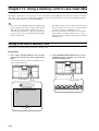
6
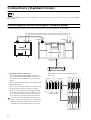
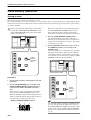
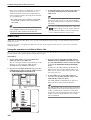
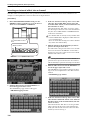
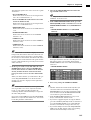
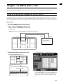
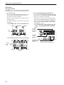
Connections (Standard mode)
This section explains connections for Standard mode, in which one console (CS1D) is connected to one engine (DSP1D-
EX {DSP1D}).
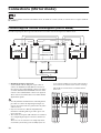
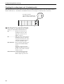
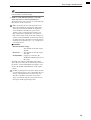
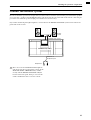
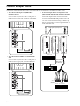
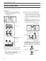
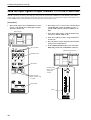
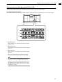
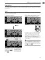
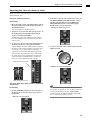
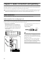
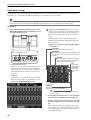
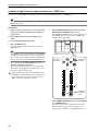
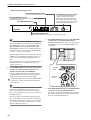
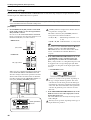
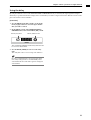
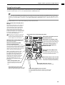
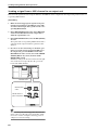
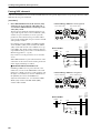
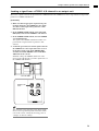
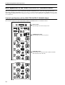
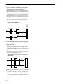
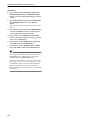
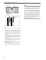
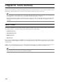
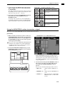
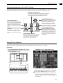
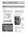
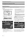
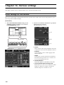
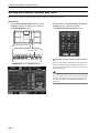
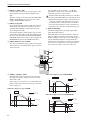
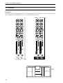
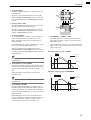
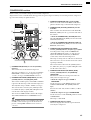
Connecting the console and engine (Standard mode)
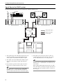
The following diagram shows typical connections between the console and engine for Standard mode.
1
Digital input/output connections
Use the included D-sub half pitch 68 pin cable to
connect the DIGITAL I/O ENGINE A connector of
the console to the CONSOLE I/O connector of the
engine.
These connectors transmit and receive multi-channel
digital audio signals.
The console and engine each have two identical digi-
tal input/output connectors, numbered 1 and 2.
These two sets of connectors are completely identi-
cal, and the system will operate normally if just one
set is connected. However, you may connect both 1
and 2 so that one of them can be used as a backup.
You must connect the identically-numbered con
-
nectors of the console and engine to each other. If
differently-numbered connectors are connected to
each other, the system will not function correctly.
This method of connection is recommended for
most cases.
DSP
x1x1
1
3
POWER SUPPLY (PW1D)
ENGINE A
2
ENGINE A
DC POWER
INPUT A
IN OUT
IN OUT
CONSOLE (CS1D)
ENGINE A
(DSP1D-EX{DSP1D})
CONTROL
I/O
CONSOLE
I/O
DIGITAL
I/O
CONTROL
I/O
1IN531
2 OUT 6 4 2
OUTPUT
CONSOLE
I/O
CASCADE
DIGITAL I/O
2
CONSOLE
1 2121
ENGINE B
DIGITAL I/O
ENGINE A
Console (CS1D)
Engine
(DSP1D-EX {DSP1D})

Connections (Standard mode)
7
Hint
If both digital input/output connectors 1 and 2 are
connected, connector 1 will be given priority when
the power is turned on.
If the word clock stops being supplied from either
connector 1 or 2 (whichever is the currently-used
connector), the receiving device will automatically
switch to the other connector.
•
Use only Yamaha-manufactured D-sub half pitch 68
pin cables to connect the digital input/output con-
nectors. Operation cannot be guaranteed if any other
cables are used.
•
If you need a cable of a different length than the
included D-sub half pitch 68 pin cable, please con-
tact your dealer.
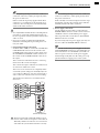
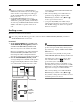
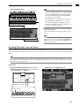
2
Control input/output connections
Use BNC cables (50
Ω
) to connect the CONTROL I/
O ENGINE A IN connector of the console to the
CONTROL I/O OUT connector of the engine, and
the CONTROL I/O ENGINE A OUT connector of
the console to the CONTROL I/O IN connector of
the engine.
These connectors transmit and receive control sig-
nals between the console and engine.
The console and engine each have two identical sets
of connectors, numbered 1 and 2.
These two sets of connectors are completely identi-
cal, and the system will operate normally if just one
set is connected. However, you may connect both 1
and 2 so that one of them can be used as a backup.
This method of connection is recommended for
most cases.
You must connect the identically-numbered con
-
nectors of the console and engine to each other. If
differently-numbered connectors are connected to
each other, the system will not function correctly.
Hint
If both control input/output connectors 1 and 2 are
connected, connector 1 will be given priority when
the power is turned on.
If the currently-used control output connector stops
functioning correctly, the receiving device will auto-
matically switch to the other connector.
3
Power supply connections
Use the included special cable to connect the DC
POWER INPUT connector of the console to the DC
OUTPUT connector of the PW1D power supply.
The rear panel of the console has two DC POWER
INPUT connectors, A and B.
If you are using only one power supply, you may con-
nect it to either DC POWER INPUT connector.
Hint
You can also connect two power supplies to the two
DC POWER INPUT connectors A and B. If this con-
nection method is used, the PM1D system will con-
tinue to operate even if one of the power supplies
should unexpectedly fail, since the other power sup-
ply will continue to supply power to the system.
22
22
IN
OUT
IN
2
OUT
IN
1
OUT
THRU
PC
CONTROL
WORD CLOCK
TIME CODE IN
GPI
RS-422
REMOTE
IN
OUT
OFF
ON
RS-232-C
USB
75Ω
MIDI CONTROL I/O
CONSOLE
CONSOLE ENGINE B ENGINE A
IN
1
2
OUT
IN
OUT
IN
1
2
OUT
IN
OUT
IN
1
2
OUT
IN
OUT
CONTROL I/O
Console (CS1D)
Engine
(DSP1D-EX {DSP1D})

CS1D Operating Manual (Start-up)
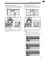
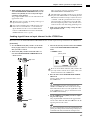
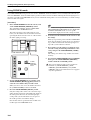
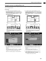
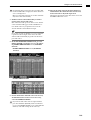
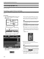
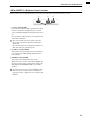
8
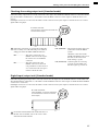
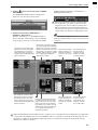
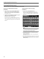
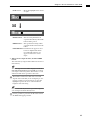
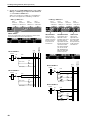
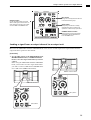
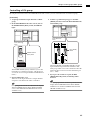
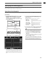
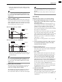
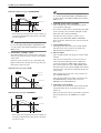
Connecting an analog input/output unit to the engine (Stan-
dard mode)
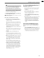
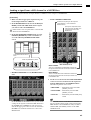
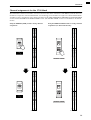
The following diagram shows a common way of making connections between the engine and analog input/output units
for Standard mode.
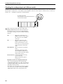
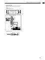
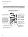
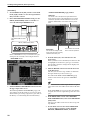
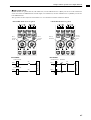
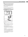
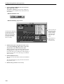
1
Analog input unit AI8 connection
Connect the OUTPUT A connector of the AI8 analog
input unit to one of the INPUT 1–INPUT 10 con-
nectors of the engine. Set the CONTROL PORT
switch (located on the rear panel of the AI8) to the A
position.
2
Analog output unit AO8 connection
Connect the INPUT A connector of the AO8 analog
output unit to one of the OUTPUT 1–OUTPUT 6
connectors of the engine. Set the INPUT SELECTOR
switch (located on the front panel of the AO8) to the
A position.
Hint
An AI8 analog input unit can be connected to any
INPUT connector of the engine, and the number of
that INPUT connector will be the ID number of that
unit. Similarly, an AO8 analog output unit can be
connected to any OUTPUT connector of the engine,
and the number of that OUTPUT connector will be
the ID number of that unit.
Be careful not to connect inputs and outputs in
reverse. If such a connection is made, the unit will
not be recognized and cannot be controlled.
ANALOG OUTPUT BOX ANALOG OUTPUT BOX
ANALOG INPUT BOXANALOG INPUT BOX
INPUT 1
INPUT 2
INPUT A INPUT AOUTPUT A OUTPUT A
OUTPUT 1
OUTPUT 2
12
ENGINE A
(DSP1D-EX{DSP1D})
AI8 (ID=2) AI8 (ID=1) AO8 (ID=1) AO8 (ID=2)
CONTROL PORT
Switch = A
INPUT SELECTOR
Switch = A
CONTROL PORT
Switch = A
INPUT SELECTOR
Switch = A

Connections (Standard mode)
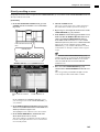
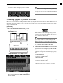
9
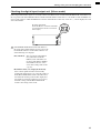
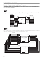
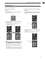
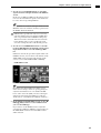
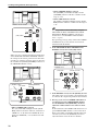
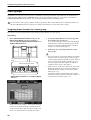
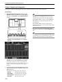
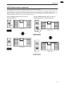
Connecting a digital input/output unit to the engine (Standard
mode)
When connecting a DIO8 digital input/output unit to the engine in Standard mode, the method will depend on whether
you use only slots 1–4 (of the DIO8’s slots 1–8) or slots 1–4 as well as slots 5–8.
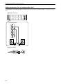
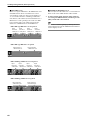
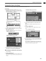
1
If input/output cards are installed only in DIO8
slots 1–4
The following diagram shows example connections
for when input/output cards are connected only to
slots 1–4 of the DIO8.
Connect the OUTPUT A connector of the digital
input/output unit to one of the INPUT 1–10 connec-
tors of the engine, and connect the INPUT A connec-
tor of the digital input/output unit to one of the
OUTPUT 1–6 connectors of the engine. In this case,
set the PORT B SELECTOR switch (located on the
front panel of the DIO8) to the 5-8 position.
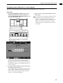
2
If input/output cards are also installed in DIO8
slots 5–8
The following diagram shows example connections
for when input/output cards are installed in DIO8
slots 1–4 and also in slots 5–8.
Connect the OUTPUT connectors A/B of the digital
input/output unit to the INPUT 1–10 connectors of
the engine, and connect the INPUT connectors A/B
of the digital input/output unit to OUTPUT 1–6
connectors of the engine. In this case, set the PORT B
SELECTOR switch (located on the front panel of the
DIO8) to the 5-8 position.
Hint
The DIO8 digital input/output unit can be con-
nected to any INPUT connector/OUTPUT connec-
tor of the engine. The DIO8 will automatically select
a control connector according to the status of con-
nections, and the connector number of the engine
connected to that connector will be displayed in the
LED display as the unit ID. In the example shown
above, the INPUT 1 connector number is the unit ID
number.
Be careful not to connect inputs and outputs in
reverse. If such a connection is made, the unit will
not be recognized and cannot be controlled.
When using an MY8-AT card to handle ADAT for
-
mat signals, synchronization may tend to be lost
easily, depending on the device that is connected.
For more reliable synchronization, we recommend
that the word clock for the combination of digital
audio equipment you are using be taken from other
than the ADAT format connector.
DIO8 (ID=1)
PORT B SELECTOR=5–8
INPUT 1
OUTPUT A INPUT A
OUTPUT 1
ENGINE A
(DSP1D-EX{DSP1D})
DIO8 (ID=1)
PORT B SELECTOR=5–8
OUTPUT INPUT
ENGINE A
(DSP1D-EX{DSP1D})
INPUT 2
INPUT 1
OUTPUT 1
OUTPUT 2
BBAA

10
Connections (Mirror mode)
This section explains connections for Mirror mode, in which one console (CS1D) is connected to two engines (DSP1D-
EX {DSP1D}).
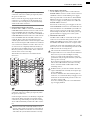
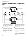
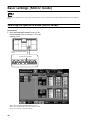
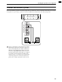
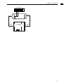
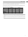
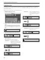
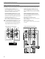
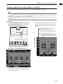
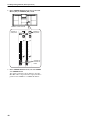
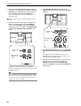
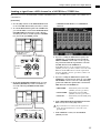
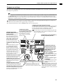
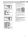
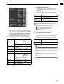
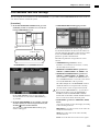
Connecting the console and engines (Mirror mode)
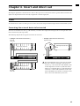
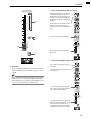
The following diagram shows typical connections between the console and engines for Mirror mode.
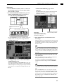
1
Digital input/output connections
Use the included D-sub half pitch 68 pin cables to
connect the DIGITAL I/O ENGINE A connector of
the console to the CONSOLE I/O connector of engine
A, and the DIGITAL I/O ENGINE B connector of the
console to the CONSOLE I/O connector of engine B.
These connectors transmit and receive multi-channel
digital audio signals.
•
Use only Yamaha-manufactured D-sub half pitch 68
pin cables to connect the digital input/output con-
nectors. Operation cannot be guaranteed if any other
cables are used.
•
If you need cables of a different length than the
included D-sub half pitch 68 pin cables, please con-
tact your dealer.
•
The console and engines A/B each have two identical
sets of digital input/output connectors, numbered 1
and 2.
These two sets of connectors are completely identi-
cal, and the system will operate normally if just one
set is connected. However, you may connect both 1
and 2 so that one of them can be used as a backup.
This method of connection is recommended for
most cases.
DSP
x2x2
3
4
POWER SUPPLY (PW1D)
DC POWER
INPUT A
ENGINE B
(DSP1D-EX{DSP1D})
12
ENGINE A ENGINE B
ENGINE A ENGINE B
IN OUT IN OUT
CONSOLE (CS1D)
ENGINE A
(DSP1D-EX{DSP1D})
CONTROL
I/O
CONSOLE
I/O
CONSOLE
I/O
DIGITAL
I/O
CONTROL
I/O
CONTROL
I/O
IN OUT
IN OUT
Clock Generator
WORD
CLOCK IN
WORD
CLOCK IN
WORD
CLOCK IN
1IN5
2 OUT 6
CONSOLE
I/O
CASCADE
2
CONSOLE
1 2121
ENGINE B
DIGITAL I/O
ENGINE A
1IN5
2 OUT 6
CONSOLE
I/O
CASCADE
Console
(CS1D)
Engine B Engine A

Connections (Mirror mode)
11
Hint
If both digital input/output connectors 1 and 2 are
connected, connector 1 will be given priority when
the power is turned on.
If the word clock stops being supplied from either
connector 1 or 2 (whichever is the currently-used
connector), the receiving device will automatically
switch to the other connector.
2 Control input/output connections
Use BNC cables (50Ω) to connect the CONTROL I/
O ENGINE A IN and OUT connectors of the console
to the CONTROL I/O OUT and IN connectors of
engine A. In the same way, connect the CONTROL I/
O ENGINE B IN and OUT connectors of the console
to the CONTROL I/O OUT and IN connectors of
engine B. These connectors transmit and receive
control signals between the console and engines A/B.
The console and engines A/B each have two identical
sets of connectors, numbered 1 and 2. These two sets
of connectors are completely identical, and the sys-
tem will operate normally if just one set is connected.
However, you may connect both 1 and 2 so that one
of them can be used as a backup.
This method of connection is recommended for
most cases.
Hint
If both control input/output connectors 1 and 2 are
connected, connector 1 will be given priority when
the power is turned on.
Control output connectors 1/2 will always output the
same signals. If the currently-used control output
connector stops functioning correctly, the receiving
device will automatically switch to the other connec-
tor.
You must connect the identically-numbered con
-
nectors of the console and engine to each other. If
differently-numbered connectors are connected to
each other, the system will not function correctly.
3
Power supply connections
Use the included special cable to connect the DC
POWER INPUT connector of the console to the DC
OUTPUT connector of the PW1D power supply.
The rear panel of the console has two DC POWER
INPUT connectors, A and B. If you are using only
one power supply, you may connect it to either DC
POWER INPUT connector.
You can also connect two power supplies to the two
DC POWER INPUT connectors A and B. If this con-
nection method is used, the PM1D system will con-
tinue to operate even if one of the power supplies
should unexpectedly fail, since the other power sup-
ply will continue to supply power to the system.
4
Word clock connections
Use BNC cables (75
Ω
) to connect the clock output
connector of an external clock generator to the
WORD CLOCK IN connector of the console, and to
the WORD CLOCK IN connectors of engines A/B.
Connect the word clock transmitting and receiving
devices in a one-to-one relationship, and turn on the
75
Ω
screen for the receiving device.
The word clock transmission/reception circuit is
designed with one-to-one connection in mind. For
this reason, if you connect multiple receiving
devices to a single clock transmission connector,
performance may be impaired and the system may
fail to operate correctly.
If you cannot avoid using this type of connection,
turn on the 75
Ω
switch for one of the receiving
devices, and turn off the 75
Ω
switches for all
remaining devices.
In Mirror mode, you can also switch to the other
engine manually if the currently-used engine expe-
riences difficulties.
In order to minimize the clock switching time in
such cases, we recommend that you supply a word
clock from an external clock generator to the con-
sole and to engines A/B.
Of course, switching will occur even without this
type of supply method.
22
22
IN
OUT
IN
2
OUT
IN
1
OUT
THRU
PC
CONTROL
WORD CLOCK
TIME CODE IN
GPI
RS-422
REMOTE
IN
OUT
OFF
ON
RS-232-C
USB
75Ω
MIDI CONTROL I/O
CONSOLE
22
22
IN
OUT
IN
2
OUT
IN
1
OUT
THRU
PC
CONTROL
WORD CLOCK
TIME CODE IN
GPI
RS-422
REMOTE
IN
OUT
OFF
ON
RS-232-C
USB
75Ω
MIDI CONTROL I/O
CONSOLE
CONSOLE ENGINE B ENGINE A
IN
1
2
OUT
IN
OUT
IN
1
2
OUT
IN
OUT
IN
1
2
OUT
IN
OUT
CONTROL I/O
Console (CS1D)
Engine B Engine A

CS1D Operating Manual (Start-up)
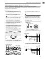
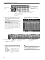
12
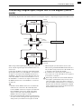
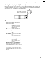
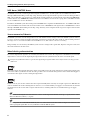
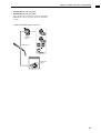
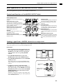
Connecting an analog input/output unit to the engines (Mirror
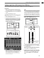
mode)
The following diagram shows a common way of making connections between the engine and analog input/output units
for Mirror mode.
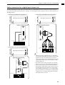
1
Analog input unit AI8 connection
Connect the OUTPUT A connector of the AI8 analog
input unit to one of the INPUT 1–INPUT 10 con-
nectors of engine A, and connect the OUTPUT B
connector of the AI8 to one of the INPUT 1–INPUT
10 connectors of engine B.
•
When using Mirror mode, OUTPUT connectors A
and B of the AI8 must be connected to the identi-
cally-numbered INPUT connector of engines A and
B. Be aware that if these are connected to differently-
numbered INPUT connectors, the content of the
input signals will change when you switch between
engines A and B.
•
When using Mirror mode, leave the CONTROL
PORT switch of the AI8 in the A position as the
default setting.
2
Analog output unit AO8 connection
Connect the INPUT A connector of the AO8 analog
output unit to one of the OUTPUT 1–OUTPUT 6
connectors of engine A. Connect the INPUT B con-
nector of the AO8 to one of the OUTPUT 1–OUT-
PUT 6 connectors of engine B.
•
When using Mirror mode, INPUT connectors A and
B of the AO8 must be connected to the identically-
numbered OUTPUT connector of engines A and B.
Be aware that if these are connected to differently-
numbered OUTPUT connectors, the content of the
output signals will change when you switch between
engines A and B.
•
When using Mirror mode, leave the INPUT SELEC-
TOR switch of the AO8 in the A position as the
default setting.
•
Be careful not to reverse the input and output. If you
do so, the unit will not be recognized, and cannot be
controlled.
ANALOG OUTPUT BOX ANALOG OUTPUT BOX
ANALOG INPUT BOXANALOG INPUT BOX
INPUT 1
INPUT 2
INPUT A INPUT AOUTPUT A OUTPUT A
INPUT B INPUT BOUTPUT B OUTPUT B
OUTPUT 1
INPUT 1
OUTPUT 1
OUTPUT 2
INPUT 2
OUTPUT 2
12
ENGINE A
(DSP1D-EX{DSP1D})
ENGINE B
(DSP1D-EX{DSP1D})
AI8 (ID=2) AI8 (ID=1) AO8 (ID=1) AO8 (ID=2)
WORD
CLOCK IN
WORD
CLOCK
IN
WORD
CLOCK IN
WORD
CLOCK IN
WORD
CLOCK IN
Clock Generator
CONTROL
PORT
Switch = A
CONTROL
PORT
Switch = A
INPUT
SELECTOR
Switch = A
INPUT
SELECTOR
Switch = A
La pagina si sta caricando...
La pagina si sta caricando...
La pagina si sta caricando...
La pagina si sta caricando...
La pagina si sta caricando...
La pagina si sta caricando...
La pagina si sta caricando...
La pagina si sta caricando...
La pagina si sta caricando...
La pagina si sta caricando...
La pagina si sta caricando...
La pagina si sta caricando...
La pagina si sta caricando...
La pagina si sta caricando...
La pagina si sta caricando...
La pagina si sta caricando...
La pagina si sta caricando...
La pagina si sta caricando...
La pagina si sta caricando...
La pagina si sta caricando...
La pagina si sta caricando...
La pagina si sta caricando...
La pagina si sta caricando...
La pagina si sta caricando...
La pagina si sta caricando...
La pagina si sta caricando...
La pagina si sta caricando...
La pagina si sta caricando...
La pagina si sta caricando...
La pagina si sta caricando...
La pagina si sta caricando...
La pagina si sta caricando...
La pagina si sta caricando...
La pagina si sta caricando...
La pagina si sta caricando...
La pagina si sta caricando...
La pagina si sta caricando...
La pagina si sta caricando...
La pagina si sta caricando...
La pagina si sta caricando...
La pagina si sta caricando...
La pagina si sta caricando...
La pagina si sta caricando...
La pagina si sta caricando...
La pagina si sta caricando...
La pagina si sta caricando...
La pagina si sta caricando...
La pagina si sta caricando...
La pagina si sta caricando...
La pagina si sta caricando...
La pagina si sta caricando...
La pagina si sta caricando...
La pagina si sta caricando...
La pagina si sta caricando...
La pagina si sta caricando...
La pagina si sta caricando...
La pagina si sta caricando...
La pagina si sta caricando...
La pagina si sta caricando...
La pagina si sta caricando...
La pagina si sta caricando...
La pagina si sta caricando...
La pagina si sta caricando...
La pagina si sta caricando...
La pagina si sta caricando...
La pagina si sta caricando...
La pagina si sta caricando...
La pagina si sta caricando...
La pagina si sta caricando...
La pagina si sta caricando...
La pagina si sta caricando...
La pagina si sta caricando...
La pagina si sta caricando...
La pagina si sta caricando...
La pagina si sta caricando...
La pagina si sta caricando...
La pagina si sta caricando...
La pagina si sta caricando...
La pagina si sta caricando...
La pagina si sta caricando...
La pagina si sta caricando...
La pagina si sta caricando...
La pagina si sta caricando...
La pagina si sta caricando...
La pagina si sta caricando...
La pagina si sta caricando...
La pagina si sta caricando...
La pagina si sta caricando...
La pagina si sta caricando...
La pagina si sta caricando...
La pagina si sta caricando...
La pagina si sta caricando...
La pagina si sta caricando...
La pagina si sta caricando...
La pagina si sta caricando...
La pagina si sta caricando...
La pagina si sta caricando...
La pagina si sta caricando...
La pagina si sta caricando...
La pagina si sta caricando...
La pagina si sta caricando...
La pagina si sta caricando...
La pagina si sta caricando...
La pagina si sta caricando...
La pagina si sta caricando...
La pagina si sta caricando...
La pagina si sta caricando...
La pagina si sta caricando...
La pagina si sta caricando...
La pagina si sta caricando...
La pagina si sta caricando...
La pagina si sta caricando...
La pagina si sta caricando...
La pagina si sta caricando...
La pagina si sta caricando...
La pagina si sta caricando...
La pagina si sta caricando...
La pagina si sta caricando...
La pagina si sta caricando...
La pagina si sta caricando...
La pagina si sta caricando...
La pagina si sta caricando...
La pagina si sta caricando...
La pagina si sta caricando...
La pagina si sta caricando...
La pagina si sta caricando...
La pagina si sta caricando...
La pagina si sta caricando...
La pagina si sta caricando...
La pagina si sta caricando...
La pagina si sta caricando...
La pagina si sta caricando...
La pagina si sta caricando...
La pagina si sta caricando...
La pagina si sta caricando...
La pagina si sta caricando...
La pagina si sta caricando...
La pagina si sta caricando...
La pagina si sta caricando...
La pagina si sta caricando...
La pagina si sta caricando...
La pagina si sta caricando...
La pagina si sta caricando...
La pagina si sta caricando...
La pagina si sta caricando...
La pagina si sta caricando...
La pagina si sta caricando...
La pagina si sta caricando...
La pagina si sta caricando...
La pagina si sta caricando...
La pagina si sta caricando...
La pagina si sta caricando...
La pagina si sta caricando...
La pagina si sta caricando...
La pagina si sta caricando...
La pagina si sta caricando...
La pagina si sta caricando...
La pagina si sta caricando...
La pagina si sta caricando...
La pagina si sta caricando...
La pagina si sta caricando...
La pagina si sta caricando...
La pagina si sta caricando...
La pagina si sta caricando...
La pagina si sta caricando...
La pagina si sta caricando...
La pagina si sta caricando...
La pagina si sta caricando...
La pagina si sta caricando...
La pagina si sta caricando...
La pagina si sta caricando...
La pagina si sta caricando...
La pagina si sta caricando...
La pagina si sta caricando...
La pagina si sta caricando...
La pagina si sta caricando...
La pagina si sta caricando...
La pagina si sta caricando...
La pagina si sta caricando...
La pagina si sta caricando...
La pagina si sta caricando...
La pagina si sta caricando...
La pagina si sta caricando...
La pagina si sta caricando...
La pagina si sta caricando...
La pagina si sta caricando...
La pagina si sta caricando...
La pagina si sta caricando...
La pagina si sta caricando...
La pagina si sta caricando...
La pagina si sta caricando...
La pagina si sta caricando...
La pagina si sta caricando...
La pagina si sta caricando...
La pagina si sta caricando...
La pagina si sta caricando...
La pagina si sta caricando...
La pagina si sta caricando...
La pagina si sta caricando...
La pagina si sta caricando...
La pagina si sta caricando...
La pagina si sta caricando...
La pagina si sta caricando...
La pagina si sta caricando...
La pagina si sta caricando...
La pagina si sta caricando...
La pagina si sta caricando...
La pagina si sta caricando...
La pagina si sta caricando...
La pagina si sta caricando...
La pagina si sta caricando...
La pagina si sta caricando...
La pagina si sta caricando...
La pagina si sta caricando...
La pagina si sta caricando...
La pagina si sta caricando...
La pagina si sta caricando...
La pagina si sta caricando...
La pagina si sta caricando...
La pagina si sta caricando...
La pagina si sta caricando...
La pagina si sta caricando...
La pagina si sta caricando...
La pagina si sta caricando...
La pagina si sta caricando...
La pagina si sta caricando...
La pagina si sta caricando...
La pagina si sta caricando...
La pagina si sta caricando...
La pagina si sta caricando...
La pagina si sta caricando...
La pagina si sta caricando...
La pagina si sta caricando...
La pagina si sta caricando...
La pagina si sta caricando...
La pagina si sta caricando...
La pagina si sta caricando...
La pagina si sta caricando...
La pagina si sta caricando...
La pagina si sta caricando...
La pagina si sta caricando...
La pagina si sta caricando...
La pagina si sta caricando...
La pagina si sta caricando...
La pagina si sta caricando...
La pagina si sta caricando...
La pagina si sta caricando...
La pagina si sta caricando...
La pagina si sta caricando...
La pagina si sta caricando...
La pagina si sta caricando...
La pagina si sta caricando...
La pagina si sta caricando...
La pagina si sta caricando...
La pagina si sta caricando...
La pagina si sta caricando...
La pagina si sta caricando...
La pagina si sta caricando...
La pagina si sta caricando...
La pagina si sta caricando...
La pagina si sta caricando...
La pagina si sta caricando...
La pagina si sta caricando...
La pagina si sta caricando...
La pagina si sta caricando...
La pagina si sta caricando...
La pagina si sta caricando...
La pagina si sta caricando...
La pagina si sta caricando...
La pagina si sta caricando...
La pagina si sta caricando...
La pagina si sta caricando...
La pagina si sta caricando...
La pagina si sta caricando...
La pagina si sta caricando...
La pagina si sta caricando...
La pagina si sta caricando...
La pagina si sta caricando...
La pagina si sta caricando...
La pagina si sta caricando...
La pagina si sta caricando...
La pagina si sta caricando...
La pagina si sta caricando...
La pagina si sta caricando...
La pagina si sta caricando...
La pagina si sta caricando...
La pagina si sta caricando...
La pagina si sta caricando...
La pagina si sta caricando...
La pagina si sta caricando...
La pagina si sta caricando...
La pagina si sta caricando...
La pagina si sta caricando...
La pagina si sta caricando...
La pagina si sta caricando...
La pagina si sta caricando...
La pagina si sta caricando...
La pagina si sta caricando...
La pagina si sta caricando...
La pagina si sta caricando...
La pagina si sta caricando...
La pagina si sta caricando...
La pagina si sta caricando...
La pagina si sta caricando...
La pagina si sta caricando...
La pagina si sta caricando...
La pagina si sta caricando...
La pagina si sta caricando...
La pagina si sta caricando...
La pagina si sta caricando...
La pagina si sta caricando...
La pagina si sta caricando...
La pagina si sta caricando...
La pagina si sta caricando...
La pagina si sta caricando...
La pagina si sta caricando...
La pagina si sta caricando...
La pagina si sta caricando...
La pagina si sta caricando...
La pagina si sta caricando...
La pagina si sta caricando...
La pagina si sta caricando...
La pagina si sta caricando...
La pagina si sta caricando...
La pagina si sta caricando...
La pagina si sta caricando...
La pagina si sta caricando...
La pagina si sta caricando...
La pagina si sta caricando...
La pagina si sta caricando...
La pagina si sta caricando...
La pagina si sta caricando...
La pagina si sta caricando...
La pagina si sta caricando...
La pagina si sta caricando...
La pagina si sta caricando...
La pagina si sta caricando...
La pagina si sta caricando...
La pagina si sta caricando...
La pagina si sta caricando...
La pagina si sta caricando...
La pagina si sta caricando...
La pagina si sta caricando...
La pagina si sta caricando...
La pagina si sta caricando...
La pagina si sta caricando...
La pagina si sta caricando...
La pagina si sta caricando...
La pagina si sta caricando...
La pagina si sta caricando...
La pagina si sta caricando...
La pagina si sta caricando...
La pagina si sta caricando...
La pagina si sta caricando...
La pagina si sta caricando...
La pagina si sta caricando...
La pagina si sta caricando...
La pagina si sta caricando...
La pagina si sta caricando...
La pagina si sta caricando...
La pagina si sta caricando...
La pagina si sta caricando...
La pagina si sta caricando...
La pagina si sta caricando...
La pagina si sta caricando...
La pagina si sta caricando...
La pagina si sta caricando...
La pagina si sta caricando...
La pagina si sta caricando...
La pagina si sta caricando...
La pagina si sta caricando...
La pagina si sta caricando...
La pagina si sta caricando...
La pagina si sta caricando...
La pagina si sta caricando...
La pagina si sta caricando...
La pagina si sta caricando...
La pagina si sta caricando...
La pagina si sta caricando...
La pagina si sta caricando...
La pagina si sta caricando...
La pagina si sta caricando...
La pagina si sta caricando...
La pagina si sta caricando...
La pagina si sta caricando...
La pagina si sta caricando...
La pagina si sta caricando...
La pagina si sta caricando...
La pagina si sta caricando...
La pagina si sta caricando...
La pagina si sta caricando...
La pagina si sta caricando...
La pagina si sta caricando...
La pagina si sta caricando...
La pagina si sta caricando...
La pagina si sta caricando...
La pagina si sta caricando...
La pagina si sta caricando...
La pagina si sta caricando...
La pagina si sta caricando...
La pagina si sta caricando...
La pagina si sta caricando...
La pagina si sta caricando...
La pagina si sta caricando...
La pagina si sta caricando...
La pagina si sta caricando...
La pagina si sta caricando...
La pagina si sta caricando...
La pagina si sta caricando...
La pagina si sta caricando...
La pagina si sta caricando...
La pagina si sta caricando...
La pagina si sta caricando...
La pagina si sta caricando...
La pagina si sta caricando...
La pagina si sta caricando...
La pagina si sta caricando...
La pagina si sta caricando...
La pagina si sta caricando...
La pagina si sta caricando...
La pagina si sta caricando...
La pagina si sta caricando...
La pagina si sta caricando...
La pagina si sta caricando...
La pagina si sta caricando...
La pagina si sta caricando...
La pagina si sta caricando...
La pagina si sta caricando...
La pagina si sta caricando...
La pagina si sta caricando...
La pagina si sta caricando...
La pagina si sta caricando...
La pagina si sta caricando...
La pagina si sta caricando...
La pagina si sta caricando...
La pagina si sta caricando...
La pagina si sta caricando...
La pagina si sta caricando...
La pagina si sta caricando...
La pagina si sta caricando...
La pagina si sta caricando...
La pagina si sta caricando...
La pagina si sta caricando...
La pagina si sta caricando...
La pagina si sta caricando...
La pagina si sta caricando...
La pagina si sta caricando...
La pagina si sta caricando...
La pagina si sta caricando...
La pagina si sta caricando...
La pagina si sta caricando...
La pagina si sta caricando...
La pagina si sta caricando...
La pagina si sta caricando...
La pagina si sta caricando...
La pagina si sta caricando...
La pagina si sta caricando...
La pagina si sta caricando...
La pagina si sta caricando...
La pagina si sta caricando...
La pagina si sta caricando...
La pagina si sta caricando...
La pagina si sta caricando...
La pagina si sta caricando...
La pagina si sta caricando...
La pagina si sta caricando...
La pagina si sta caricando...
La pagina si sta caricando...
La pagina si sta caricando...
La pagina si sta caricando...
La pagina si sta caricando...
La pagina si sta caricando...
La pagina si sta caricando...
La pagina si sta caricando...
La pagina si sta caricando...
La pagina si sta caricando...
La pagina si sta caricando...
La pagina si sta caricando...
La pagina si sta caricando...
La pagina si sta caricando...
La pagina si sta caricando...
La pagina si sta caricando...
La pagina si sta caricando...
La pagina si sta caricando...
La pagina si sta caricando...
La pagina si sta caricando...
La pagina si sta caricando...
La pagina si sta caricando...
La pagina si sta caricando...
La pagina si sta caricando...
La pagina si sta caricando...
La pagina si sta caricando...
La pagina si sta caricando...
La pagina si sta caricando...
La pagina si sta caricando...
La pagina si sta caricando...
La pagina si sta caricando...
La pagina si sta caricando...
La pagina si sta caricando...
La pagina si sta caricando...
La pagina si sta caricando...
La pagina si sta caricando...
La pagina si sta caricando...
La pagina si sta caricando...
La pagina si sta caricando...
La pagina si sta caricando...
La pagina si sta caricando...
La pagina si sta caricando...
La pagina si sta caricando...
La pagina si sta caricando...
La pagina si sta caricando...
La pagina si sta caricando...
La pagina si sta caricando...
La pagina si sta caricando...
La pagina si sta caricando...
La pagina si sta caricando...
La pagina si sta caricando...
La pagina si sta caricando...
La pagina si sta caricando...
La pagina si sta caricando...
La pagina si sta caricando...
La pagina si sta caricando...
La pagina si sta caricando...
La pagina si sta caricando...
La pagina si sta caricando...
La pagina si sta caricando...
La pagina si sta caricando...
La pagina si sta caricando...
La pagina si sta caricando...
La pagina si sta caricando...
La pagina si sta caricando...
La pagina si sta caricando...
La pagina si sta caricando...
La pagina si sta caricando...
La pagina si sta caricando...
La pagina si sta caricando...
La pagina si sta caricando...
La pagina si sta caricando...
La pagina si sta caricando...
La pagina si sta caricando...
La pagina si sta caricando...
La pagina si sta caricando...
La pagina si sta caricando...
La pagina si sta caricando...
La pagina si sta caricando...
La pagina si sta caricando...
La pagina si sta caricando...
La pagina si sta caricando...
La pagina si sta caricando...
La pagina si sta caricando...
La pagina si sta caricando...
La pagina si sta caricando...
La pagina si sta caricando...
La pagina si sta caricando...
La pagina si sta caricando...
La pagina si sta caricando...
La pagina si sta caricando...
La pagina si sta caricando...
La pagina si sta caricando...
La pagina si sta caricando...
La pagina si sta caricando...
La pagina si sta caricando...
La pagina si sta caricando...
La pagina si sta caricando...
La pagina si sta caricando...
La pagina si sta caricando...
La pagina si sta caricando...
La pagina si sta caricando...
La pagina si sta caricando...
La pagina si sta caricando...
La pagina si sta caricando...
La pagina si sta caricando...
La pagina si sta caricando...
La pagina si sta caricando...
La pagina si sta caricando...
La pagina si sta caricando...
La pagina si sta caricando...
La pagina si sta caricando...
La pagina si sta caricando...
La pagina si sta caricando...
La pagina si sta caricando...
La pagina si sta caricando...
La pagina si sta caricando...
La pagina si sta caricando...
La pagina si sta caricando...
La pagina si sta caricando...
La pagina si sta caricando...
La pagina si sta caricando...
La pagina si sta caricando...
La pagina si sta caricando...
La pagina si sta caricando...
La pagina si sta caricando...
La pagina si sta caricando...
La pagina si sta caricando...
La pagina si sta caricando...
La pagina si sta caricando...
La pagina si sta caricando...
-
 1
1
-
 2
2
-
 3
3
-
 4
4
-
 5
5
-
 6
6
-
 7
7
-
 8
8
-
 9
9
-
 10
10
-
 11
11
-
 12
12
-
 13
13
-
 14
14
-
 15
15
-
 16
16
-
 17
17
-
 18
18
-
 19
19
-
 20
20
-
 21
21
-
 22
22
-
 23
23
-
 24
24
-
 25
25
-
 26
26
-
 27
27
-
 28
28
-
 29
29
-
 30
30
-
 31
31
-
 32
32
-
 33
33
-
 34
34
-
 35
35
-
 36
36
-
 37
37
-
 38
38
-
 39
39
-
 40
40
-
 41
41
-
 42
42
-
 43
43
-
 44
44
-
 45
45
-
 46
46
-
 47
47
-
 48
48
-
 49
49
-
 50
50
-
 51
51
-
 52
52
-
 53
53
-
 54
54
-
 55
55
-
 56
56
-
 57
57
-
 58
58
-
 59
59
-
 60
60
-
 61
61
-
 62
62
-
 63
63
-
 64
64
-
 65
65
-
 66
66
-
 67
67
-
 68
68
-
 69
69
-
 70
70
-
 71
71
-
 72
72
-
 73
73
-
 74
74
-
 75
75
-
 76
76
-
 77
77
-
 78
78
-
 79
79
-
 80
80
-
 81
81
-
 82
82
-
 83
83
-
 84
84
-
 85
85
-
 86
86
-
 87
87
-
 88
88
-
 89
89
-
 90
90
-
 91
91
-
 92
92
-
 93
93
-
 94
94
-
 95
95
-
 96
96
-
 97
97
-
 98
98
-
 99
99
-
 100
100
-
 101
101
-
 102
102
-
 103
103
-
 104
104
-
 105
105
-
 106
106
-
 107
107
-
 108
108
-
 109
109
-
 110
110
-
 111
111
-
 112
112
-
 113
113
-
 114
114
-
 115
115
-
 116
116
-
 117
117
-
 118
118
-
 119
119
-
 120
120
-
 121
121
-
 122
122
-
 123
123
-
 124
124
-
 125
125
-
 126
126
-
 127
127
-
 128
128
-
 129
129
-
 130
130
-
 131
131
-
 132
132
-
 133
133
-
 134
134
-
 135
135
-
 136
136
-
 137
137
-
 138
138
-
 139
139
-
 140
140
-
 141
141
-
 142
142
-
 143
143
-
 144
144
-
 145
145
-
 146
146
-
 147
147
-
 148
148
-
 149
149
-
 150
150
-
 151
151
-
 152
152
-
 153
153
-
 154
154
-
 155
155
-
 156
156
-
 157
157
-
 158
158
-
 159
159
-
 160
160
-
 161
161
-
 162
162
-
 163
163
-
 164
164
-
 165
165
-
 166
166
-
 167
167
-
 168
168
-
 169
169
-
 170
170
-
 171
171
-
 172
172
-
 173
173
-
 174
174
-
 175
175
-
 176
176
-
 177
177
-
 178
178
-
 179
179
-
 180
180
-
 181
181
-
 182
182
-
 183
183
-
 184
184
-
 185
185
-
 186
186
-
 187
187
-
 188
188
-
 189
189
-
 190
190
-
 191
191
-
 192
192
-
 193
193
-
 194
194
-
 195
195
-
 196
196
-
 197
197
-
 198
198
-
 199
199
-
 200
200
-
 201
201
-
 202
202
-
 203
203
-
 204
204
-
 205
205
-
 206
206
-
 207
207
-
 208
208
-
 209
209
-
 210
210
-
 211
211
-
 212
212
-
 213
213
-
 214
214
-
 215
215
-
 216
216
-
 217
217
-
 218
218
-
 219
219
-
 220
220
-
 221
221
-
 222
222
-
 223
223
-
 224
224
-
 225
225
-
 226
226
-
 227
227
-
 228
228
-
 229
229
-
 230
230
-
 231
231
-
 232
232
-
 233
233
-
 234
234
-
 235
235
-
 236
236
-
 237
237
-
 238
238
-
 239
239
-
 240
240
-
 241
241
-
 242
242
-
 243
243
-
 244
244
-
 245
245
-
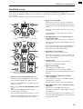 246
246
-
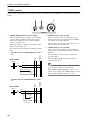 247
247
-
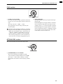 248
248
-
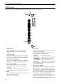 249
249
-
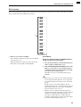 250
250
-
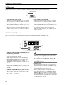 251
251
-
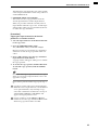 252
252
-
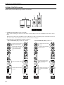 253
253
-
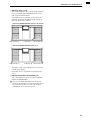 254
254
-
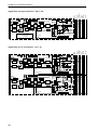 255
255
-
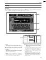 256
256
-
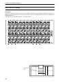 257
257
-
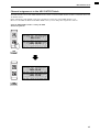 258
258
-
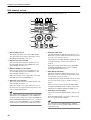 259
259
-
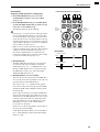 260
260
-
 261
261
-
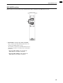 262
262
-
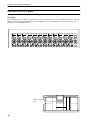 263
263
-
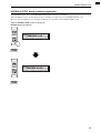 264
264
-
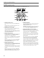 265
265
-
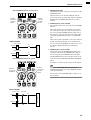 266
266
-
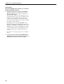 267
267
-
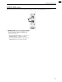 268
268
-
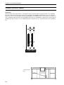 269
269
-
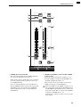 270
270
-
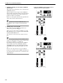 271
271
-
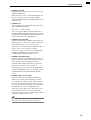 272
272
-
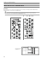 273
273
-
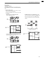 274
274
-
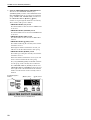 275
275
-
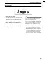 276
276
-
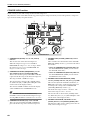 277
277
-
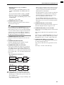 278
278
-
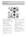 279
279
-
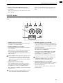 280
280
-
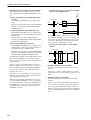 281
281
-
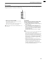 282
282
-
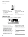 283
283
-
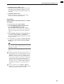 284
284
-
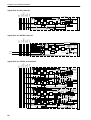 285
285
-
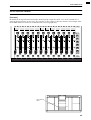 286
286
-
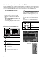 287
287
-
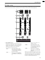 288
288
-
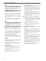 289
289
-
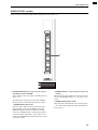 290
290
-
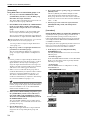 291
291
-
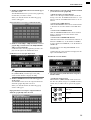 292
292
-
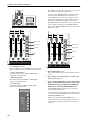 293
293
-
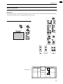 294
294
-
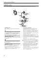 295
295
-
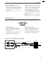 296
296
-
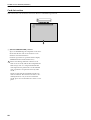 297
297
-
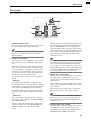 298
298
-
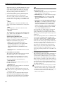 299
299
-
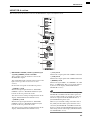 300
300
-
 301
301
-
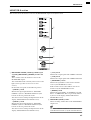 302
302
-
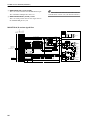 303
303
-
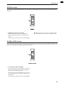 304
304
-
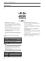 305
305
-
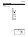 306
306
-
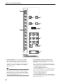 307
307
-
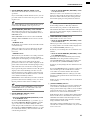 308
308
-
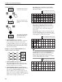 309
309
-
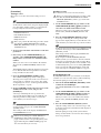 310
310
-
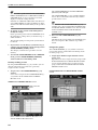 311
311
-
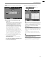 312
312
-
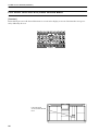 313
313
-
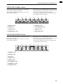 314
314
-
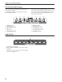 315
315
-
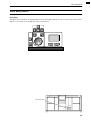 316
316
-
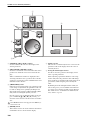 317
317
-
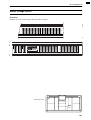 318
318
-
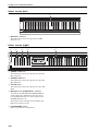 319
319
-
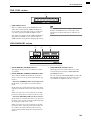 320
320
-
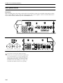 321
321
-
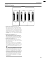 322
322
-
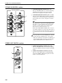 323
323
-
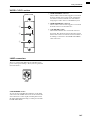 324
324
-
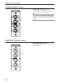 325
325
-
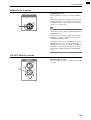 326
326
-
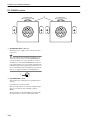 327
327
-
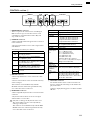 328
328
-
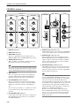 329
329
-
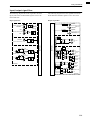 330
330
-
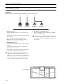 331
331
-
 332
332
-
 333
333
-
 334
334
-
 335
335
-
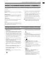 336
336
-
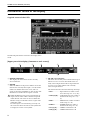 337
337
-
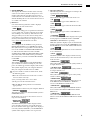 338
338
-
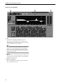 339
339
-
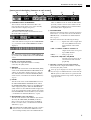 340
340
-
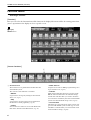 341
341
-
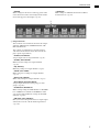 342
342
-
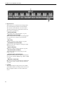 343
343
-
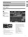 344
344
-
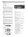 345
345
-
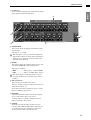 346
346
-
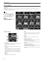 347
347
-
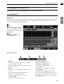 348
348
-
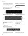 349
349
-
 350
350
-
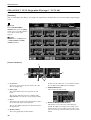 351
351
-
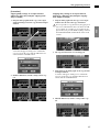 352
352
-
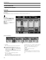 353
353
-
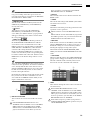 354
354
-
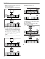 355
355
-
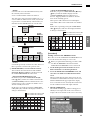 356
356
-
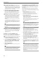 357
357
-
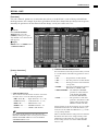 358
358
-
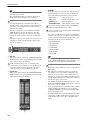 359
359
-
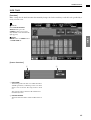 360
360
-
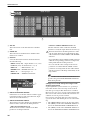 361
361
-
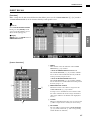 362
362
-
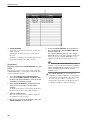 363
363
-
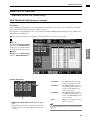 364
364
-
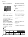 365
365
-
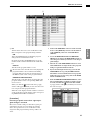 366
366
-
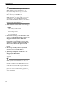 367
367
-
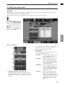 368
368
-
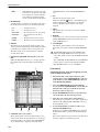 369
369
-
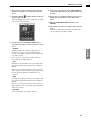 370
370
-
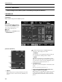 371
371
-
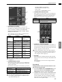 372
372
-
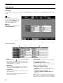 373
373
-
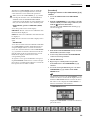 374
374
-
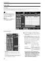 375
375
-
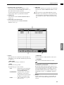 376
376
-
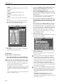 377
377
-
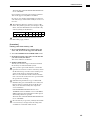 378
378
-
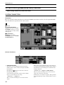 379
379
-
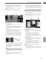 380
380
-
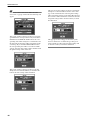 381
381
-
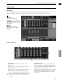 382
382
-
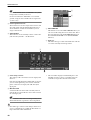 383
383
-
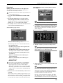 384
384
-
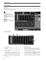 385
385
-
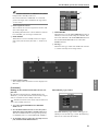 386
386
-
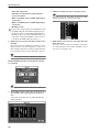 387
387
-
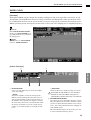 388
388
-
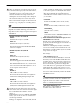 389
389
-
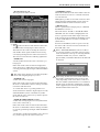 390
390
-
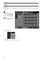 391
391
-
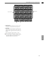 392
392
-
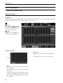 393
393
-
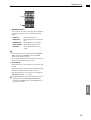 394
394
-
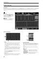 395
395
-
 396
396
-
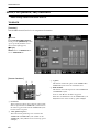 397
397
-
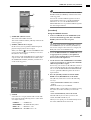 398
398
-
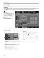 399
399
-
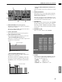 400
400
-
 401
401
-
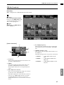 402
402
-
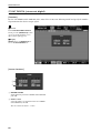 403
403
-
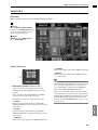 404
404
-
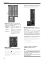 405
405
-
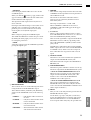 406
406
-
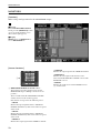 407
407
-
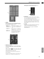 408
408
-
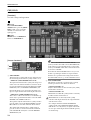 409
409
-
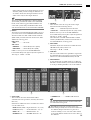 410
410
-
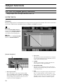 411
411
-
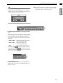 412
412
-
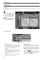 413
413
-
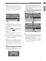 414
414
-
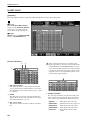 415
415
-
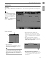 416
416
-
 417
417
-
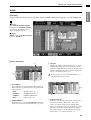 418
418
-
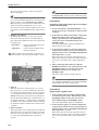 419
419
-
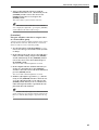 420
420
-
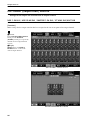 421
421
-
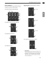 422
422
-
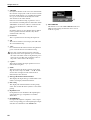 423
423
-
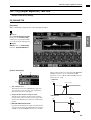 424
424
-
 425
425
-
 426
426
-
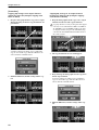 427
427
-
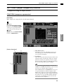 428
428
-
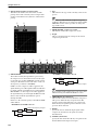 429
429
-
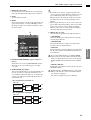 430
430
-
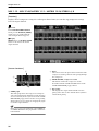 431
431
-
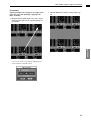 432
432
-
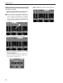 433
433
-
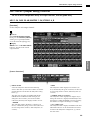 434
434
-
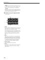 435
435
-
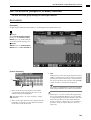 436
436
-
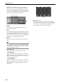 437
437
-
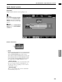 438
438
-
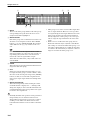 439
439
-
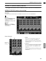 440
440
-
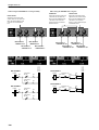 441
441
-
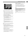 442
442
-
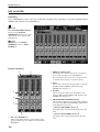 443
443
-
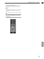 444
444
-
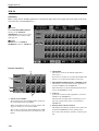 445
445
-
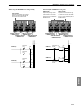 446
446
-
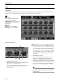 447
447
-
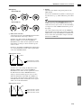 448
448
-
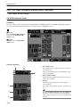 449
449
-
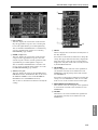 450
450
-
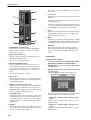 451
451
-
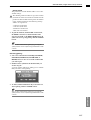 452
452
-
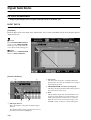 453
453
-
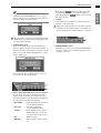 454
454
-
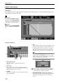 455
455
-
 456
456
-
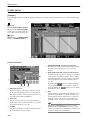 457
457
-
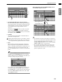 458
458
-
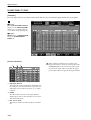 459
459
-
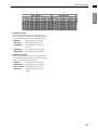 460
460
-
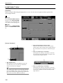 461
461
-
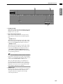 462
462
-
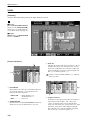 463
463
-
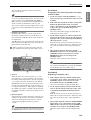 464
464
-
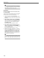 465
465
-
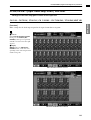 466
466
-
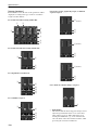 467
467
-
 468
468
-
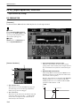 469
469
-
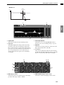 470
470
-
 471
471
-
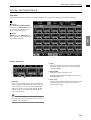 472
472
-
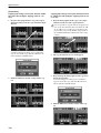 473
473
-
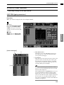 474
474
-
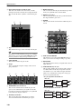 475
475
-
 476
476
-
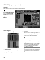 477
477
-
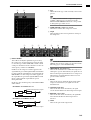 478
478
-
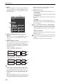 479
479
-
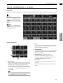 480
480
-
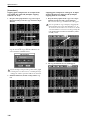 481
481
-
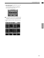 482
482
-
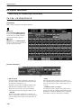 483
483
-
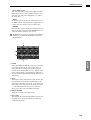 484
484
-
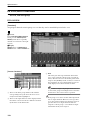 485
485
-
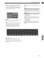 486
486
-
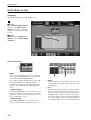 487
487
-
 488
488
-
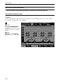 489
489
-
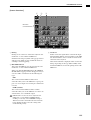 490
490
-
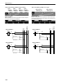 491
491
-
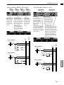 492
492
-
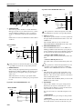 493
493
-
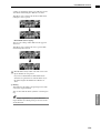 494
494
-
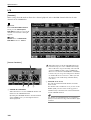 495
495
-
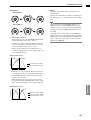 496
496
-
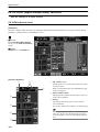 497
497
-
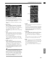 498
498
-
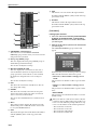 499
499
-
 500
500
-
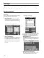 501
501
-
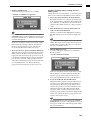 502
502
-
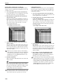 503
503
-
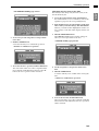 504
504
-
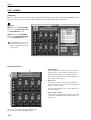 505
505
-
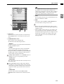 506
506
-
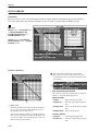 507
507
-
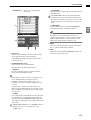 508
508
-
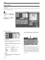 509
509
-
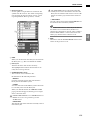 510
510
-
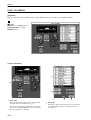 511
511
-
 512
512
-
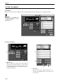 513
513
-
 514
514
-
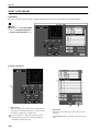 515
515
-
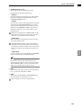 516
516
-
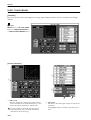 517
517
-
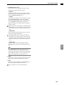 518
518
-
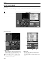 519
519
-
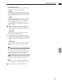 520
520
-
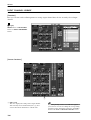 521
521
-
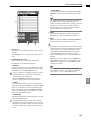 522
522
-
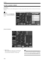 523
523
-
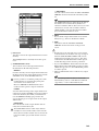 524
524
-
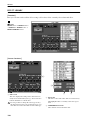 525
525
-
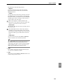 526
526
-
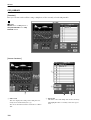 527
527
-
 528
528
-
 529
529
-
 530
530
-
 531
531
-
 532
532
-
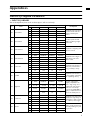 533
533
-
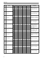 534
534
-
 535
535
-
 536
536
-
 537
537
-
 538
538
-
 539
539
-
 540
540
-
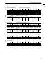 541
541
-
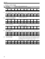 542
542
-
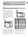 543
543
-
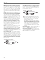 544
544
-
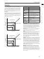 545
545
-
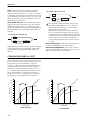 546
546
-
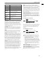 547
547
-
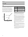 548
548
-
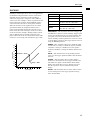 549
549
-
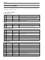 550
550
-
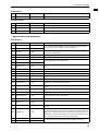 551
551
-
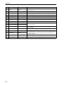 552
552
-
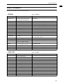 553
553
-
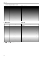 554
554
-
 555
555
-
 556
556
-
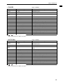 557
557
-
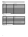 558
558
-
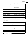 559
559
-
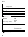 560
560
-
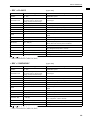 561
561
-
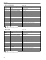 562
562
-
 563
563
-
 564
564
-
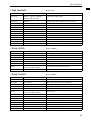 565
565
-
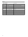 566
566
-
 567
567
-
 568
568
-
 569
569
-
 570
570
-
 571
571
-
 572
572
-
 573
573
-
 574
574
-
 575
575
-
 576
576
-
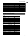 577
577
-
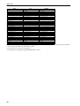 578
578
-
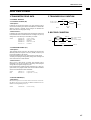 579
579
-
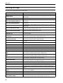 580
580
-
 581
581
-
 582
582
-
 583
583
-
 584
584
-
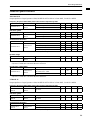 585
585
-
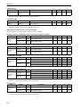 586
586
-
 587
587
-
 588
588
-
 589
589
-
 590
590
-
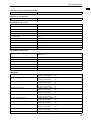 591
591
-
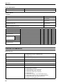 592
592
-
 593
593
-
 594
594
-
 595
595
-
 596
596
-
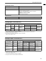 597
597
-
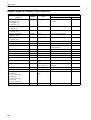 598
598
-
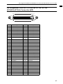 599
599
-
 600
600
-
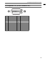 601
601
-
 602
602
-
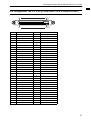 603
603
-
 604
604
-
 605
605
-
 606
606
-
 607
607
-
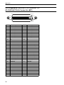 608
608
-
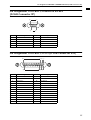 609
609
-
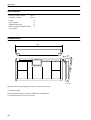 610
610
-
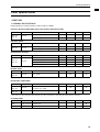 611
611
-
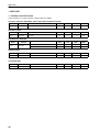 612
612
-
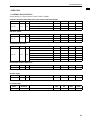 613
613
-
 614
614
-
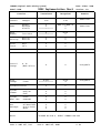 615
615
-
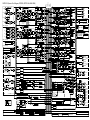 616
616
-
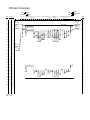 617
617


Yamaha CS1D Manuale del proprietario
- Categoria
- Mixer audio
- Tipo
- Manuale del proprietario
in altre lingue
- English: Yamaha CS1D Owner's manual
- français: Yamaha CS1D Le manuel du propriétaire
- español: Yamaha CS1D El manual del propietario
- Deutsch: Yamaha CS1D Bedienungsanleitung
- русский: Yamaha CS1D Инструкция по применению
- Nederlands: Yamaha CS1D de handleiding
- português: Yamaha CS1D Manual do proprietário
- dansk: Yamaha CS1D Brugervejledning
- čeština: Yamaha CS1D Návod k obsluze
- polski: Yamaha CS1D Instrukcja obsługi
- svenska: Yamaha CS1D Bruksanvisning
- Türkçe: Yamaha CS1D El kitabı
- română: Yamaha CS1D Manualul proprietarului
Documenti correlati
Altri documenti
-
Optimus DP-0206 Manuale utente
-
TC Electronic M-ONE XL Manuale del proprietario
-
Grace m906 Manuale del proprietario
-
MarkBass Bass Multiamp Scheda dati
-
Ingersoll-Rand X4i Quick Setup Manual
-
 Fandis FF13PA230UFR Manuale utente
-
agape ARUB0968N_MM Assembly Instructions
-
TC Electronic FINALIZER 96K Manuale del proprietario
