La pagina si sta caricando...

Gas
Manuale installazione e uso
User and installation manual
Installations- und Gebrauchshandbuch
made in Italy

Gas - IT/UK/DE 08-12 3
Premessa ......................................................................................................................................................... 6
Avvertenze iniziali .......................................................................................................................................... 7
Dati tecnici “Gas” monocamera ...................................................................................................................... 8
Dati tecnici “Gas” bicamera ............................................................................................................................. 9
Caratteristiche generali ................................................................................................................................ 10
Predisposizioni per l’installazione .............................................................................................................. 11
Avvertenze per l’installatore ....................................................................................................................... 12
Scarico e trasporto / Preparazione e controllo ........................................................................................... 13
Posizionamento ............................................................................................................................................ 14
Prescrizioni di legge, regole tecniche e direttive / Collegamento elettrico ............................................. 15
Collegamento del gas ................................................................................................................................... 16
Pressioni per il collegamento ...................................................................................................................... 17
Controllo della pressione d’alimentazione ................................................................................................. 18
Controllo del funzionamento ....................................................................................................................... 19
Attivazione alimentazione / Verica del funzionamento / Precollaudo ................................................... 20
Trasformazione o adattamento ................................................................................................................... 21
Accensione e spegnimento camera di cottura ............................................................................................ 22
Avvertenze per l’utilizzatore ........................................................................................................................ 23
Istruzioni d’uso / Avvertenze per la sicurezza ............................................................................................. 24
Avvertenze per la manutenzione ................................................................................................................. 25
Pirolisi / Pulizia e cura ................................................................................................................................... 26
Posizionamento comandi principali ............................................................................................................ 27
Schemi elettrici ............................................................................................................................................. 28
Parti di ricambio ..................................................................................................................................... 29 - 30
Condizioni di garanzia / Limiti ed esclusioni .............................................................................................. 31
INDICE
La pagina si sta caricando...
La pagina si sta caricando...

6 Gas - IT/UK/DE 08-12
6
Premessa
La lingua originale del presente manuale è
l’italiano. Altre lingue sono traduzioni.
Ci complimentiamo con Lei per aver scelto
un prodotto progettato e realizzato con
tecnologie all’avanguardia.
Per poter utilizzare al meglio questo prodot-
to, Vi consigliamo di leggere attentamente il
contenuto del presente manuale, onde evita-
re spiacevoli inconvenienti.
Esso contiene importanti indicazioni e avver-
tenze riguardanti l’installazione, l’uso e la ma-
nutenzione del prodotto.
Il forno da Voi acquistato è stato progettato
e realizzato con la massima cura, sottoposto
a severi test di collaudo nei nostri laboratori,
pertanto assicuriamo l’assoluta sicurezza e
funzionalità dello stesso.
L’installazione deve essere eettuata secondo
le istruzioni da personale professionalmente
qualicato, in grado di assumersi la respon-
sabilità dell’intervento e garantire le migliori
condizioni di funzionamento e sicurezza.
ASSISTENZA TECNICA
Il produttore è in grado di risolvere qualun-
que problema tecnico riguardante l’impie-
go e la manutenzione.
Nella remota eventualità di un cattivo fun-
zionamento o riparazione, rivolgersi esclu-
sivamente a personale qualicato o ai no-
stri centri di assistenza autorizzati.
Introduction
The present manual was originally written
in Italian. All other languages are transla-
tions.
Congratulations on selecting a product
that was designed and constructed with
advanced technology.
We recommend that you read through this
manual fully before using this appliance. It
contains very important information and
instructions regarding installation, use and
maintenance.
The oven you have purchased was carefully
designed and constructed and has been sub-
jected to strict inspection tests in our labora-
tories, therefore we can guarantee its absolute
safety and functionality.
Installation must be done according to the in-
structions by professionally qualied person-
nel who are able to take on the responsibility
for the installation and guarantee the best
conditions for operation and safety.
TECHNICAL SUPPORT
The manufacturer is able to solve any tech-
nical problem concerning use and mainte-
nance.
In the remote possibility of poor operation
or a repair, only use qualied personnel or
contact our authorised service centres.
Vorwort
Die Originalsprache dieser Anleitung ist
italienisch. Bei allen anderen Sprachen
handelt es sich um Übersetzungen.
Wir möchten Sie dazu beglückwünschen,
dass Sie ein Produkt gewählt haben, das
mit neuesten Technologien entwickelt und
hergestellt wurde.
Um dieses Produkt bestmöglich einzusetzen,
empfehlen wir Ihnen, den Inhalt des vorlie-
genden Handbuchs aufmerksam zu lesen, um
Unannehmlichkeiten zu vermeiden.
Es enthält wichtige Angaben und Hinweise zu
Installation, Gebrauch und Wartung des Pro-
dukts.
Der von Ihnen gekaufte Ofen wurde mit äu-
ßerster Sorgfalt entwickelt und gebaut und
in unseren Labors strengen Abnahmeprüfun-
gen unterzogen. Daher können wir für die
absolute Sicherheit und Funktionstüchtigkeit
des Ofens garantieren.
Die Installation muss nach den Anweisungen
von qualiziertem Fachpersonal vorgenom-
men werden, die die Verantwortung für den
Eingri übernehmen können und die die be-
sten Betriebs- und Sicherheitsbedingungen
garantieren können.
TECHNISCHER KUNDENDIENST
Der Hersteller kann jedes technische Pro-
blem zu Einsatz und Wartung lösen.
Sollte es wirklich zu Betriebsstörungen
oder einer Reparatur kommen, wenden Sie
sich ausschließliche an qualiziertes Per-
sonal oder an eines unserer autorisierten
Kundendienstzentren.

Gas - IT/UK/DE 08-12 7
7
Avvertenze iniziali
ATTENZIONE!
Il mancato rispetto di quanto descritto nel
presente libretto, può compromettere la
sicurezza.
• Ilmanualedeveessereconservatoconcura
ed in luogo accessibile, inoltre deve sempre
accompagnare il prodotto nell’arco della
sua vita.
Prima dell’installazione e utilizzo del forno è
indispensabile leggere attentamente il pre-
sente manuale ed attenersi scrupolosamen-
te alle indicazioni riportate.
• Il produttore declina ogni responsabilità
civile e penale, per danni a persone, cose
o animali, derivanti dalla mancata osser-
vanza delle norme di sicurezza vigenti, dal
mancato rispetto dei contenuti del presente
manuale e da eventuali errori di stampa o
trascrizione dello stesso.
Dichiara inoltre di riservarsi il diritto di ap-
portare al prodotto, tutte le modiche che
riterrà opportune senza obbligo di preavvi-
so.
• Primadiqualsiasimovimentazionedelpro-
dotto, installazione o uso, accertarsi della
idoneità del locale che ospiterà lo stesso.
Assicurarsi di aver adottato tutte le misure
antinfortunistiche necessarie onde evitare il
pericolo di incidenti.
• L’installazione del forno deve essere eet-
tuata da personale qualicato in ottempe-
ranza delle norme vigenti.
• Alcunepartidelfornopossonoraggiunge-
re temperature elevate. Si consiglia di fare
attenzione a non toccare le superci e non
avvicinare materiali che possono essere in-
ammabili. La presenza di bambini, anziani
e/o disabili richiede la vigilanza di un adulto
consapevole.
• In presenza di un cattivo funzionamento,
non utilizzare il forno e rivolgersi al centro
di assistenza più vicino.
• L’apparecchiaturadeveessereutilizzatasolo
da personale addestrato all’uso della stessa.
• Ilfornoèunprodottoutilizzabileperlacot-
tura di pizza o prodotti analoghi, ogni altro
uso è da ritenersi improprio.
• Controllare periodicamente l’ecienza dei
condotti di scarico.
• Perqualsiasianomaliaointerventisulpro-
dotto rivolgersi esclusivamente a personale
autorizzato. Per la sostituzione di compo-
nenti usare solo ricambi originali.
ATTENZIONE:
PERICOLO DI INCENDIO
Ogni 3 mesi aprire il vano comandi e aspi-
rare accuratamente gli eventuali depositi
di farina o polvere!
WARNING:
RISK OF FIRE
Every 3 months, open the control unit and
carefully vacuum any our or dust depo-
sits!
ACHTUNG:
BRANDGEFAHR
Alle 3 Monate muss der Raum mit den
Steuerelementen geönet werden, um
sorgfältig eventuelle Mehl- und Staubabla-
gerungen absaugen zu können!
Initial instructions
ATTENTION!
Failure to comply with what is described in
this handbook could jeopardise safety.
• The manual must be kept carefully and in
an accessible location, it must also always
accompany the product during its life.
Before installing and using the oven, this
manual must be read carefully and the in-
structions it contains must be followed scru-
pulously.
• Themanufacturerdeclines allciviland cri-
minal liability for damage to people, pro-
perty or animals deriving from the failure to
observe current safety regulations, failure
to respect the contents of this manual and
from any printing or transcription errors.
It also declares that it reserves the right to
make any changes to the product that it
considers appropriate without the obliga-
tion to provide notice.
• Beforehandling,installingorusingthepro-
duct, verify the suitability of the room whe-
re it will be located. Make sure that all safety
measures have been taken in order to avoid
any accidents.
• Theovenmustbeinstalledbyqualiedper-
sonnel in compliance with current regula-
tions.
• Some parts of the oven may reach very
high temperatures. Be careful not to touch
the surfaces and to not bring material near
the oven that may be inammable. The pre-
sence of children, elderly or disabled indivi-
duals requires supervision of a responsible
adult.
• Inthecaseofpooroperation,donotusethe
oven and contact your nearest service cen-
tre.
• Theequipmentmayonlybeusedbypeople
who have been trained in its use.
• Theovenisaproductusedforbakingpizzas
or similar products, any other uses must be
considered improper.
• Periodicallychecktheexhaustducts.
• If a fault occurs, contact only authorised
personnel. Use only original spare parts
when replacing components.
Einleitende Hinweise
ACHTUNG!
Eine Nichteinhaltung der Angaben in der
vorliegenden Anleitung kann die Sicher-
heit beeinträchtigen.
• Das Handbuch muss an einer zugänglichen
Stelle sorgfältig aufbewahrt werden, vor allem
muss es das Produkt über den gesamten Le-
benszyklus begleiten.
Vor der Installation und der Verwendung des
Ofens muss das vorliegende Handbuch unbe-
dingt aufmerksam gelesen werden. Die hier
gemachten Angaben müssen genauestens
eingehalten werden.
• Der Hersteller lehnt jede zivil- oder strafrechtli-
che Haftung für Schäden an Personen, Sachen
oder Tieren ab, die aus der Nichteinhaltung der
geltenden Sicherheitsvorschriften, der Nicht-
einhaltung der Anweisungen im vorliegenden
Handbuch oder durch etwaige Druck- oder Ko-
pierfehler im Handbuch entstehen.
Er erklärt darüber hinaus, dass er sich das Recht
vorbehält, ohne die Picht zur vorherigen An-
kündigung alle zweckmäßigen Änderungen am
Produkt vorzunehmen.
• VorjedemHandlingdesProdukts,jederInstalla-
tion und jeder Verwendung ist die Tauglichkeit
des Raumes zu prüfen, in dem es sich bendet.
Es ist sicherzustellen, dass alle notwendigen Un-
fallschutzmaßnahmen getroen wurden, um die
Gefahr von Unfäl-len auszuschalten.
• Die Installation des Ofens muss von quali-
ziertem Personal unter Einhaltung der gelten-
den Bestimmungen durchgeführt werden.
• Einige Ofenteile können hoheTemperaturen
erreichen. Es muss darauf geachtet werden,
die Oberächen nicht zu berühren und kei-
ne Materialien in die Nähe zu bringen, die
entzündlich sein können. Sind Kinder, ältere
Menschen und/oder Behinderte anwesend,
muss eine Überwachung durch einen verant-
wortungsvollen Erwachsenen erfolgen.
• Bei einer Fehlfunktion den Ofen nicht mehr
verwenden und sich an das nächstgelegene
Kundendienstzentrum wenden.
• DasGerätdarfnurvonPersonalbedientwer-
den, das in den Gebrauch des Geräts einge-
wiesen wurde.
• DerOfenisteinProdukt,dasszumBackenvon
Pizza und ähnlichen Produkten verwendet
werden kann, jede weitere Nutzung gilt als
unsachgemäß.
• RegelmäßigdieWirksamkeitderAbwasserlei-
tungen überprüfen.
• BeijederStörungoderjedemEingriamPro-
dukt ausschließlich an autorisiertes Fachper-
sonal wenden. Für den Austausch von Teilen
nur Original-Ersatzteile verwenden.

8 Gas - IT/UK/DE 08-12
8
ON ON
RESE T
OFFOFF
SET
H’
50
65
Ø1/2”
50
225
90 100 30
L’ P’
Ø152
L
P
H
H”
P”
L”
Dimensioni imballo
Packaging dimensions
Abmessungen Verpackung
DATI TECNICI TECHNICAL DATA
TECHNISCHE DATEN
Modello Model Modell G4 - 33 G6 - 33 G9 - 33
Dimensioni
camera di cottura
Cookingchamber
dimensions
Maße der
Backkammer
L mm
P mm
H mm
680
680
150
680
1010
150
1010
1010
150
Dimensioni
esterne
External
dimensions
Außenmaße
L’ mm
P’ mm
H’ mm
1060
970
500
1060
1300
500
1390
1300
500
Capacità
di cottura pizze
Pizza baking
capacity
Kapazität Backen
von Pizzen
Nr.
4
(Ø330 mm)
1
(Ø450 mm)
6
(Ø330 mm)
2
(Ø450 mm)
9
(Ø330 mm)
4
(Ø450 mm)
Alimentazione elettrica
(50/60 Hz)
Electric power supply
(50/60 Hz)
Stromversorgung
(50/60 Hz)
Volt AC230 AC230 AC230
Portata termica Heat output Wärmeleistung
kW
max
14 20 24
Assorbimento Input Aufnahme
W 25 25 50
Cavodiallacciamento
(nxmm
2
)
Connectioncable
(nxmm
2
)
Anschlusskabel
(nxmm
2
)
(230V)
3x1mm
2
3x1mm
2
3x1mm
2
Protezione minima a bordo
quadrocliente(nxA)
Minimum protection relative
tocustomerpanel(nxA)
Minimaler Schutz am
Schaltpult des Kunden
(nxA)
(230V)
2x10 2x10 2x10
ConsumoGasliquido Liquid Gas consumption Verbrauch Flüssigas kg/h 1,10 1,58 1,89
ConsumoGasMetano
gruppo H
Natural Gas (group H)
consumption
Verbrauch Erdgas
Gruppe H
m
3
/h 1,48 2,12 2,54
Peso netto Net weight Nettogewicht Kg 155 217 291
Dimensioni
esterne con imballo
Externaldimensions
including packaging
Außenmaße
der Verpackung
L” mm
P” mm
H” mm
1110
1090
670
1110
1420
670
1440
1420
670
Peso lordo Gross weight Bruttogewicht Kg 172 238 316
(*) - Mantenere tra il forno e le altre apparecchiature o materiali inammabili, una distanza minima di almeno 50 mm.
Consigliamodilasciare500mmdispazioliberosulancodestroperconsentireunfacileaccessoall’impiantoelettrico.
Lasciare libero lo spazio superiore del forno.
(*)
Ensure that you keep a dis-
tance of at least 50 mm be-
tween the oven and other
equipment or inammable
materials.
We advise that you leave
an unrestricted space of at
least 500 mm to the right
side to allow for easy access
to the electrical system.
Leave the space above the
oven.
(*)
Halten Sie zwischen dem
Ofen und anderen Appa-
raten oder entzündlichen
Materialien einen Mindest-
abstand von 50 mm ein.
Wir raten in jedem Fall dazu,
an der rechten Seitenwand
mindestens 500 mm Platz
zu lassen, um einen einfa-
chen Zugang zur elektri-
schen Anlage zu ermögli-
chen.
Lassen Sie den Raum über
dem Ofen frei.
L - L’ - L”: larghezza - width - Breite P - P’ - P”: profondità - depth - Tiefe H - H’ - H”: altezza - height - Höhe

Gas - IT/UK/DE 08-12 9
9
RESET
ON
OF F
ON
OFF
SET
RESET
OF F
ON
OFF
ON
SET
H’
225
L’
5050
P’
65
90 100 10030 30
370
152
L
P
HH
Ø1/2”
Ø1/2”
H”
P”
L”
DATI TECNICI TECHNICAL DATA
TECHNISCHE DATEN
Modello Model Modell G8 - 33 G12 - 33 G18 - 33
Dimensioni
camera di cottura
Cookingchamber
dimensions
Maße der
Backkammer
L mm
P mm
H mm
680
680
150
680
1010
150
1010
1010
150
Dimensioni
esterne
External
dimensions
Außenmaße
L’ mm
P’ mm
H’ mm
1060
970
1000
1060
1300
1000
1390
1300
1000
Capacità
di cottura pizze
Pizza baking
capacity
Kapazität Backen
von Pizzen
Nr.
4+4
(Ø330)
1+1
(Ø450)
6+6
(Ø330)
2+2
(Ø450)
9+9
(Ø330)
4+4
(Ø450)
Alimentazione elettrica
(50/60 Hz)
Electric power supply
(50/60 Hz)
Stromversorgung
(50/60 Hz)
Volt AC230 AC230 AC230
Portata termica Heat output Wärmeleistung
kW
max
2x14 2x20 2x24
Assorbimento Input Aufnahme
W 50 50 100
Cavodiallacciamento
(nxmm
2
)
Connectioncable
(nxmm
2
)
Anschlusskabel
(nxmm
2
)
(230V)
2x(3x1mm
2
) 2x(3x1mm
2
) 2x(3x1mm
2
)
Protezione minima a bordo
quadrocliente(nxA)
Minimum protection relative
tocustomerpanel(nxA)
Minimaler Schutz am
Schaltpult des Kunden
(nxA)
(230V)
2x(2x10) 2x(2x10) 2x(2x10)
ConsumoGasliquido Liquid Gas consumption Verbrauch Flüssigas kg/h 2,21 3,15 3,79
ConsumoGasMetano
gruppo H
Natural Gas (group H)
consumption
Verbrauch Erdgas
Gruppe H
m
3
/h 2,96 4,23 5,08
Peso netto Net weight Nettogewicht Kg 332 454 600
Dimensioni
esterne con imballo
Externaldimensions
including packaging
Außenmaße
der Verpackung
L” mm
P” mm
H” mm
2x(1110)
2x(1090)
2x(670)
2x(1110)
2x(1420)
2x(670)
2x(1440)
2x(1420)
2x(670)
Peso lordo Gross weight Bruttogewicht Kg 2x(172) 2x(238) 2x(316)
Dimensioni imballo
Packaging dimensions
Abmessungen Verpackung
(*) - Mantenere tra il forno e le altre apparecchiature o materiali inammabili, una distanza minima di almeno 50 mm.
Consigliamodilasciare500mmdispazioliberosulancodestroperconsentireunfacileaccessoall’impiantoelettrico.
Lasciare libero lo spazio superiore del forno.
(*)
Ensure that you keep a dis-
tance of at least 50 mm be-
tween the oven and other
equipment or inammable
materials.
We advise that you leave
an unrestricted space of at
least 500 mm to the right
side to allow for easy access
to the electrical system.
Leave the space above the
oven.
(*)
Halten Sie zwischen dem
Ofen und anderen Appa-
raten oder entzündlichen
Materialien einen Mindest-
abstand von 50 mm ein.
Wir raten in jedem Fall dazu,
an der rechten Seitenwand
mindestens 500 mm Platz
zu lassen, um einen einfa-
chen Zugang zur elektri-
schen Anlage zu ermögli-
chen.
Lassen Sie den Raum über
dem Ofen frei.
L - L’ - L”: larghezza - width - Breite P - P’ - P”: profondità - depth - Tiefe H - H’ - H”: altezza - height - Höhe

10 Gas - IT/UK/DE 08-12
10
Caratteristiche generali
1 Cameradicotturainacciaioinossidabile
2 Evacuazione gas combusti
3 Piano di cottura in mattoni refrattari
4 Illuminazione interna
5 Facciata in acciaio inossidabile
6 Ingresso gas
7 Controllodellatemperatura
8 Attacco equipotenziale
9 Ingresso cavo alimentazione
Per avere le caratteristiche speciche del
proprio modello consultare la tabella dati
tecnici (pagine 8 e 9).
ON
OFF
RESET
OFF
G9 - 33
°C
2
1
5
4
9
8
6
3
7
General Specications
1 Stainless steel cooking chamber
2 Extractionofuegases
3 Firebrick cooking surface
4 Internal lighting
5 Stainless steel face
6 Gas inlet
7 Controloftemperatures
8 Connection
9 Power supply cable inlet
To access the specications explicit to your
model, consult the technical data table
(pages 8 and 9).
Allgemeine Eigenschaften
1 Backkammer aus rostfreiem Edelstahl
2 Ablaß Verbrannter gase
3 Backplatte aus Schamottestein
4 Innenbeleuchtung
5 Vorderseite aus rostfreiem Edelstahl
6 Gaseingang
7 Kontrolle der Temperatur
8 Potentialausgleich
9 Eingang Zuleitungskabel
Die spezischen Eigenschaften Ihres Mo-
dells nden Sie in der Tabelle mit den tech-
nischen Daten (Seite 8 und 9).

Gas - IT/UK/DE 08-12 11
11
Predisposizioni
per l’installazione
Prima di procedere con l’installazione veri-
fìcare le seguenti condizioni necessarie per il
corretto funzionamento e manutenzione del
forno:
1) Movimentazione:
Accertarsi che la pavimentazione sia in gra-
do di supportare il peso del forno.
Movimentare il forno imballato utilizzando
un carrello elevatore e/o un transpallet.
2) Collegamento del gas:
L’installazione, l’adattamento ad un altro
tipo di gas e la manutenzione devono es-
sere eettuate da un tecnico autorizzato.
Preventivamente è necessario farsi rilascia-
re dall’ente erogatore del gas il nulla osta
all’installazione.
3) Collegamento elettrico:
Prevedere una scatola di allacciamento alla
rete elettrica nelle immediate vicinanze.
4) Aerazione:
Il forno deve essere installato in un luogo
che consenta una adeguata ventilazione
secondo le normative vigenti.
In ambienti chiusi è obbligatoria una presa
d’aria ø14 cm che comunichi con l’esterno
o con un locale ventilato (es. magazzino,
sotta,garage,sottoscala).
5) Evacuazione dei fumi:
Il forno deve essere posto in un ambiente
ben aerato, possibilmente sotto una cappa
aspirante.
6) Distanze di sicurezza:
È assolutamente necessario rispettare le
distanze minime di sicurezza tra il forno e
le altre apparecchiature o materiali inam-
mabili (vedi pagina 14).
Inoltre è vietato impiegare il forno in am-
bienti a rischio di esplosione.
Le distanze indicate devono essere aumen-
tate in presenza di materiali sensibili al ca-
lore.
Installation
requirements
Before starting the installation, check the fol-
lowing conditions that are necessary for prop-
er oven operation and maintenance:
1) Handling:
Make sure that the oor is able to support
the weight of the oven.
Handle the packaged oven using a forklift
or a pallet truck.
2) Gas connection:
Installation, conversion to another type of
gas and maintenance should be carried
out by an authorised technician local gas
board.
3) Electrical connection:
Provide a box for the connection to the
mains power supply in the immediate sur-
roundings.
4) Ventilation:
The oven must be installed in an area that
permits suitable ventilation according to
current law.
In closed environments, a ø14 cm air in-
take is required that communicates with
theexteriororwithaventilatedroom(ex.
warehouse, attic, garage, space below a
staircase).
5) Fume evacuation:
The oven should be placed in a well-venti-
latedroom,ifpossibleunderanextraction
hood.
6) Safety distances:
It is mandatory that the minimum safety
distances between the oven and the other
equipment or inammable material are re-
spected (see page 14).
It is also prohibited to use the oven in areas
atriskofexplosion.
The indicated distances must be increased
in the presence of heat sensitive material.
Vorbereitungen
für die Installation
Vor dem Fortfahren mit der Installation prüfen,
ob die nachfolgenden notwendigen Bedingun-
gen für ordnungsgemäßen Betrieb und korrek-
te Wartung des Ofens erfüllt sind:
1) Handling
Prüfen, ob der Bodenbelag das Gewicht des
Ofens tragen kann. Für das Handling des ver-
packten Ofens einen Hubwagen und/oder
eine Transpalette verwenden.
2) Gasanschluß:
Der Anschluß, die Gasumstellung und die
Wartung des Gerätes dürfen nur von zuge-
lassenen Technikern durchgeführt werden.
3) Elektroanschluss:
In der unmittelbaren Umgebung einen An-
schlusskasten an die Stromversorgung vor-
sehen.
4) Belüftung:
Der Ofen muss an einem Ort installiert wer-
den, der über eine ausreichende Belüftung
nach den geltenden Vorschriften verfügt.
In geschlossenen Räumen muss ein Luftein-
lass mit ø14 cm vorhanden sein, mit einer
Verbindung ins Freie oder zu einem belüfte-
ten Raum (Bsp. Lager, Dachboden, Garage,
Raum unter der Treppe).
5) Rauchabzugssystem:
Den Ofen in einem gut belüfteten Raum
aufstellen, wenn möglich unter einer Ab-
zugshaube.
6) Sicherheitsabstände:
Die Mindestsicherheitsabstände zwischen
Ofen und anderen Geräten oder entamm-
barem Material müssen unbedingt eingehal-
ten werden (siehe Seite 14).
Darüber hinaus ist der Betrieb des Ofens in
RäumenmitExplosionsgefahrverboten.
Die angegebenen Abstände müssen erhöht
werden, wenn wärmeempndliche Materi-
alien vorhanden sind.

12 Gas - IT/UK/DE 08-12
12
Avvertenze per
l’installatore
Gli impianti di gas, acqua, energia elettrica
e i locali di installazione degli apparecchi
devono rispondere alle norme di sicurezza,
antinfortunistiche e antincendio in vigore
nel Paese di utilizzo; in caso contrario il
Costruttore non risponderà per eventuali
danni diretti o indiretti a persone o cose.
ATTENZIONE!
Scollegare il forno dall’alimentazione
elettrica e dalla rete di distribuzione del
gas durante le operazioni di installazione,
manutenzione o riparazione dell’apparec-
chiatura.
Prima di eseguire il collegamento elettrico,
accertarsi che la tensione e la frequenza ripor-
tate sulla targhetta caratteristiche corrispon-
dano a quelle dell’impianto d’alimentazione.
A monte dell’apparecchiatura deve essere
installato un interruttore di protezione auto-
matico, di portata adeguata, che abbia una
distanza d’apertura dei contatti che consenta
la disconnessione completa.
(le caratteristiche relative alla distanza di aper-
tura dei contatti e alla corrente di dispersione
massima vanno comunque recepite dalla nor-
mativa vigente).
E’ indispensabile collegare l’apparecchiatura
adunecaceimpiantoditerra.
L’apparecchiatura inoltre deve essere inclusa
in un sistema equipotenziale mediante la vite
posta sul retro del forno in basso a sinistra
contrassegnata dal simbolo
Tale sistema equipotenziale deve obbligato-
riamente ottemperare alle norme in vigore.
Installare l’apparecchio in un luogo ben aerato
poichè un non corretto ricircolo d’aria impedi-
sce il funzionamento ottimale ed il “benesse-
re” delle persone che lavorano in prossimità
dell’apparecchiatura.
Non ostruire il sistema di ventilazione dell’am-
biente in cui è installata questa apparecchia-
tura. Non ostruire i fori di aerazione e di scari-
co di questa o di altre apparecchiature.
Alla ne dell’installazione, smaltire gli imbal-
li secondo quanto indicato nelle normative
ecologiche e ambientali del luogo.
I materiali usati per l’imballo sono compatibili
con l’ambiente e si possono conservare senza
pericolo o bruciare in un apposito impianto di
combustione dei riuti.
I componenti in plastica soggetti a smalti-
mento con riciclaggio sono contrassegnati
con questo simbolo
Instructions for
the installer
The gas, water, electrical systems and the
rooms where the equipment will be in-
stalled must comply with the safety, ac-
cident prevention and re prevention
standards applicable in the country of use;
otherwise the Manufacturer shall not be
liable for any direct or indirect damage to
people or property.
ATTENTION!
Disconnect the oven from the electricity
supply and the mains gas supply before
starting any maintenance work.
Before making the electrical connection, make
sure that the voltage and frequency stated on
the specications plate corresponds to those
of the power supply.
A circuit breaker with auto-protection and suf-
cient capacity must be installed upstream of
the equipment; it must have a contact open-
ing distance that permits complete discon-
nection.
(the specications regarding the opening
distance of the contacts and the maximum
leakage current must be taken from current
regulations).
The equipment must be earth bonded.
The equipment must also be connected to an
equipotential system using the screw locat-
ed at the back of the oven, to the lower left,
marked with the symbol
This equipotential system must comply with
current standards.
Install the equipment in a well ventilated area,
as incorrect air recirculation impedes optimal
operation and the “wellbeing” of the people
working near the equipment.
Do not obstruct the ventilation system in the
area where the equipment is installed. Do not
obstructtheventilationandexhaustholesin
this or any other equipment.
At the end of installation, dispose of the pack-
aging pursuant to local ecological and envi-
ronmental regulations.
The material used for packaging is compatible
with the environment and can be kept safely
or burnt in a specic waste combustion sys-
tem.
The plastic components subject to disposal with
recycling are marked with this symbol
Hinweise für
den Installateur
Die Anlagen für Gas, Wasser und Strom,
sowie die Räume für die Installation der
Geräte müssen den im Verwendungsland
geltenden Vorschriften zu Sicherheit, Un-
fallverhütung und Brandschutz entspre-
chen. Andernfalls haftet der Hersteller
nicht für etwaige direkte oder indirekte
Personen- oder Sachschäden.
ACHTUNG!
Vor allen Wartungsarbeiten, die aus-
schließlich von qualiziertem Fachperso-
nal vorgenommen werden dürfen, ist es
notwendig die Elektrizitäts- und Gasver-
sorgung zu unterbrechen.
Vor der Ausführung des Elektroanschlusses
prüfen, ob die auf dem Typenschild angege-
bene Spannung und Frequenz denen der An-
lage zur Stromspeisung entsprechen.
Vor dem Gerät muss ein automatischer
Schutzschalter mit ausreichender Leistung in-
stalliert werden, dessen Önungsabstand der
Kontakte eine vollständige Trennung erlaubt.
(Die Eigenschaften zum Önungsabstand der
Kontakte und dem maximalen Fehlerstrom
müssen in jedem Fall den geltenden Vor-
schriften entnommen werden).
Das Gerät muss unbedingt an eine wirksame
Erdung angeschlossen werden.
Daneben muss das Gerät an ein Potentialaus-
gleichssystem angeschlossen werden, mit Hilfe
der Schraube, die sich unten links an der Rück-
seite des Ofens bendet, mit dem Zeichen
Dieses Potentialausgleichssystem muss un-
bedingt den geltenden Vorschriften entspre-
chen.
Das Gerät in einem gut gelüfteten Raum in-
stallieren, da ein nicht ordnungsgemäßer
Rückuss der Luft den optimalen Betrieb und
das «Wohlbenden» der Personen, die in der
Nähe des Geräts arbeiten, verhindert.
Das Ventilationssystem des Raums, in dem
dieses Gerät installiert wurde, nicht versper-
ren. Die Önungen für Zu- und Abluft von
diesem oder anderen Geräten nicht versper-
ren.
Nach Beendigung der Installation die Verpak-
kung nach den örtlichen Umweltschutzvor-
schriften entsorgen.
Die für die Verpackung verwendeten Materi-
alien sind nicht umweltschädlich und können
gefahrlos aufbewahrt oder in einer entspre-
chenden Müllverbrennungsanlage verbrannt
werden.
Die Plastikteile, die dem Recycling zugeführt
werden müssen, sind gekennzeichnet mit
diesem Symbol

Gas - IT/UK/DE 08-12 13
13
Preparazione e controllo
Sballare il forno e togliere con cura la pellicola
protettiva.
Qualora restassero residui di colla sulle super-
ci, eliminarli con acqua saponata e non con
prodotti corrosivi.
ATTENZIONE!
Controllare che tutte le parti costituenti il
forno siano in buono stato e non presenti-
no vizi o rotture, in caso contrario avvisare
la casa produttrice per le procedure da se-
guire.
Preparations and Checks
Unwrap the oven and carefully remove the
protective lm.
In the instance where glue residue remains on
surfaces, remove then using soapy water; do
not use corrosive products.
ATTENTION!
Check that all oven parts are in good con-
dition and that there are no defects or
breakages; in such an instance, contact the
manufacturer who will advise you on the
procedure to follow.
Vorbereitung und Kontrolle
Den Ofen auspacken und die Schutzfolie vor-
sichtig entfernen.
Sollten Leimrückstände auf der Oberäche
zurückbleiben, beseitigen Sie sie mit Seifen-
wasser und nicht mit ätzenden Produkten.
ACHTUNG!
Prüfen Sie, dass alle Teile des Ofens in gu-
tem Zustand sind und keinerlei Mängel
oder Brüche aufweisen; sollte dies der Fall
sein, wenden Sie sich an den Hersteller für
die weitere Vorgehensweise.
A
Scarico e trasporto
Unloading and transport
Entladen und Transport
ATTENTION
A
B
H
2
O
G9 - 33
°C
G9 - 33
°C
A

14 Gas - IT/UK/DE 08-12
14
Positioning
Position the oven onto its support or any
other base made of non-ammable materials
which is completely level and which is able
to support the oven weight (see the table on
pages 8 and 9).
Aufstellung
Stellen Sie den Ofen auf sein Gestell oder ei-
nen anderen Sockel aus nicht entzündbarem
Material, der waagerecht ausgerichtet und für
sein Gewicht ausgelegt ist (siehe Tabelle Seite
8 und 9).
G9 - 33
°C
G9 - 33
°C
Posizionamento
Posizionare il forno sopra il suo supporto o un
qualsiasi altro basamento costruito in mate-
riale non inammabile, in bolla e che ne sop-
porti il peso (vedere tabella pagina 8 e 9).
Mantenere tra il forno e le altre apparecchia-
ture o materiali inammabili, una distanza mi-
nima di almeno 50 mm.
Consigliamo comunque di lasciare almeno
500 mm di spazio libero sul anco destro per
consentire un facile accesso all’impianto elet-
trico.
Se ciò non è possibile, in caso di intervento,
sarà necessario spostare il forno dal suo allog-
giamento mediante adeguati sistemi di solle-
vamento.
Ensure that you keep a distance of at least 50
mm between the oven and other equipment
or inammable materials.
We advise that you leave an unrestricted space
of at least 500 mm to the right side to allow for
easy access to the electrical system.
Where this is not possible, you will have to
move the oven from its housing using suit-
able lifting systems.
Halten Sie zwischen dem Ofen und anderen
Apparaten oder entzündlichen Materialien ei-
nen Mindestabstand von 50 mm ein.
Wir raten in jedem Fall dazu, an der rechten
Seitenwand mindestens 500 mm Platz zu las-
sen, um einen einfachen Zugang zur elektri-
schen Anlage zu ermöglichen.
Wenn dies nicht möglich ist, muss der Ofen
für Wartungs-/Reparatureingrie mittels ge-
eigneter Hubvorrichtungen an einen anderen
Platz gebracht werden.
min.
50 mm
min.
500 mm
min.
50 mm

Gas - IT/UK/DE 08-12 15
15
Durante l’installazione dell’apparecchio sono
da osservare le seguenti prescrizioni:
• normedileggevigentiinmateria.
• normeregionaliqualiregolamentoedilizio
e prescrizioni inerenti la combustione.
• regoletecnicheperl’installazioneagas.
• regoletecnicheperGPL.
• installazione apparecchi a gas per grandi
cucine.
• normeantinfortunistichevigenti.
• normedell’aziendaerogatricedelgas.
• normativesugliimpiantielettrici.
• Norme e regolamentiin vigore nel paese,
come le norme sull‘edilizia e i regolamenti
antincendio.
• Normerelativealpostodilavoro.Direttive
per l‘edilizia relative ai requisiti tecnici an-
tincendio per gli impianti di ventilazione.
• FogliodilavoroDVGWG634„Installazione
di Grandi cucine – Dispositivi a gas“.
• FogliodilavoroDVGWG600(TRGI)“Norme
tecniche per gli impianti a gas”.
• “Regole tecniche per il gas liquido” (TRF),
requisiti applicabili per la prevenzione de-
gli infortuni e direttive per le cucine e il gas
liquido.
• Direttiveeclausole applicabilidelleazien-
de fornitrici di gas (GVU).
L’apparecchio deve essere installato nel ri-
spetto dello standard EN 1717 e delle norma-
tive nazionali vigenti in materia di impianti
idraulici.
The following regulations are to be complied
with during installation of the appliance:
• legalregulationsonthesubject.
• regionalregulationssuchasbuildingregu-
lations and specications concerning com-
bustion.
• technicalrulesforgasinstallation.
• technicalrulesforLPG.
• installationofgasappliancesforprofessio-
nal kitchens.
• currentaccident-preventionregulations.
• gasboardregulations.
• regulationsandstandardsonelectricalsy-
stems.
• Standardsandregulationscurrentlyinforce
in the country, such as standards governing
building and re prevention regulations.
• Standards governing the work place. Bu-
ilding directives relative to technical, re
prevention requirements for ventilation sy-
stems.
• Code of Practice DVGW G634“Installation
ofGasappliancesinCommercialkitchens”.
• CodeofPracticeDVGWG600(TRGI)“Tech-
nical specications for gas appliances”.
• “Technicalregulationsforliquidgas”(TRF),
applicable requirements for the preven-
tion of accidents and directives governing
kitchens and liquid gas.
• Applicabledirectivesandagreementspro-
vided by gas suppliers (GVU).
The appliance must be installed in conformi-
ty with Standard EN 1717 and national stan-
dards in force with regards hydraulic systems.
Während der Installation des Gerätes müssen
folgende Vorschriften beachtet werden:
• GültigeGesetze.
• Örtliche Baund Brandverhütungs -vorschrif-
ten.
• VorschriftenfürmitGasbetriebeneAnlagen.
• VorschriftenfürFlüssiggas.
• Installation von gasbetriebenen Geräten für
Großküchen.
• GültigeUnfallverhütungsvorschriften.
• Bestimmungen der Gasversorgungsgesell-
schaft.
• VorschriftenfürelektrischeAnlagen.
• EntsprechendeRechtsverordungenwie Bau-
ordnungen und Feuerungsverordnungen der
Länder.
• Verordnungen über Arbeitsstatten. Bauauf-
sichtliche Richtlinien über die brandschutz-
technischenAnforderungen an Lüftungsanla-
gen.
• DVGW -Arbeitsblatt G634 „Installation von
Großküchen-Gasverbrauchseinrichtungen“.
• DVGW-Arbeitsblatt G600 (TRGI) „Technische
Regeln für Gasinstallationen“.
• TRF „Technische Regeln für Flüssiggas“, Ein-
schlägige Unfallverhütungsvorschriften und
Richtlinien für Küchen und FIüssiggas.
• Einschlägige Richtlinien und Bestimmungen
des Gasversor-gungsunternehmen (GVU).
Das Gerät muss in Konformität mit EN 1717 und
den geltenden nationalen Regelwerken über
Wasserinstallationen installiert werden.
Prescrizioni di legge, regole tecniche
e direttive
Legal and technical regulations and
directives
Gesetzliche bestimmungen, Techni-
sche Vorschriften und richtlinien

16 Gas - IT/UK/DE 08-12
16
Collegamento del gas
Il collegamento deve essere eettuato esclu-
sivamente da un’impresa autorizzata.
Prima di collegare l’apparecchio alla rete del
gas, controllare sulla targhetta supplementa-
re che esso sia predisposto e collaudato per il
tipo di gas disponibile.
Qualora ciò non accadesse, consultare il para-
grafo ”Trasformazione e adattamento”.
Il collegamento alla rete di distribuzione del
gas deve avvenire con tubi metallici di diame-
tro adeguato e con l’interposizione di un rubi-
netto d’intercettazione omologato.
Se vengono utilizzati tubi essibili, questi de-
vono essere d’acciaio inossidabile secondo la
normaUNI-CIG.
A monte del collegamento nelle vicinanze del
forno devono essere previste le seguenti ap-
parecchiature:
- valvola di chiusura.
- regolatore di pressione.
(solo per il modello a GPL).
La rampa di collegamento si trova sulla parete
posteriore in basso a sinistra ed è conforme
alla norma ISO 7-1 con lettatura esterna.
Terminati i lavori d’installazione procedere,
con pressione di funzionamento, al controllo
di tenuta dei raccordi per eliminare eventuali
perdite; allo scopo è bene utilizzare delle so-
stanze schiumose non corrosive, per esempio
spray cercafughe.
Durante la prova di tenuta è assolutamen-
te vietato utilizzare amme libere!
Gas connections
Connectionshouldonlybecarriedoutbyan
authorised rm.
Before connecting the appliance to the gas
mains, check on the supplementary rating
plate that it is set up and tested for the type
of gas available.
If this is not the case, consult the paragraph
“Conversion and adaptation”.
Metal pipes with a suitable diameter should
be used for connection to the mains gas net-
work and an approved cut-o cock inserted.
If hoses are used, they should be in stainless
steeltoUNI-CIGstandards.
The following equipment should be tted on
the supply pipe near the oven:
- stop valve;
- pressure regulator.
(for the LPG model only).
The gas injet connection is to be found on the
rear wall at the bottom left and is in compli-
ancewiththeISO7-1standardwithexternal
screw thread.
Upon completion of installation, check the
tting and connections for leaks at working
pressure; it is advisable to use non-corrosive
foamy substances, e.g. leak-nder sprays, for
this purpose.
During the test for leaks, it is absolutely
forbidden to use a naked ame!
Gasanschluss
Der Gasanschluß darf nur von einem autori-
sierten Unternehmen vorgenommen werden.
Bevor der Ofen an das Gasnetz angeschlossen
wird kontrollieren Sie das Zusatzschild und
vergewissern Sie sich, daß das verfügbare Gas
dem entspricht, für das der Ofen ausgelegt
ist. Sollte dies nicht der Fall sein, so konsultie-
ren Sie bitte den Paragraphen „Veränderung
und Gasumstellung“.
Der Anschluß an das Gasversorgungsnetz
muß mit Metallrohren von passendem Durch-
messer und mit der Zwischenschaltung eines
zulässigen Absperrhahnes erfolgen.
Sollten biegsame Schlauchleitungen benutzt
werden, so müssen diese nach Richtlinie UNI-
CIGausrostfreiemStahlgefertigtsein.
Am oberen Ende des Anschlusses und in der
Nähe des Ofens müssen folgende Vorrichtun-
gen vorgesehen werden:
- Absperrventil.
- Druckregler.
(nur für das Flüssiggas-Modell)
Die Anschlußführung bendet sich links
unten an der Ofenrückseite und ist gemäß
Richtlinie Iso 7-1 mit einer äußeren Bohrung
versehen.
Nach Abschluß der Anschlußarbeiten muß bei
Betriebsdruck die Dichtheit der Verbindungs-
stücke überprüft werden. Zu diesem Zweck
sollte eine schäumende, korrosionsfreie Sub-
stanz wie zum Beispiel Lecksuchspray benutzt
werden.
Während der Dichtheitsprüfung darf unter
keinen Umständen mit einer oenen Flam-
me gerarbeitet werden!
Collegamento elettrico
Il collegamento elettrico deve essere eseguito
esclusivamente da personale qualicato.
La targhetta dati tecnici, posta sul retro del
forno, contiene tutte le informazioni necessa-
rie per un corretto allacciamento.
L’apparecchio deve essere collegato alla rete
di alimentazione con un cavo del tipo H05
RN-F (fornito dall’installatore).
Per eettuare questa operazione togliere il
pannello laterale destro del forno, collegare il
cavo alla morsettiera e fermarlo con l’apposito
pressacavo situato sul retro del apparecchio
stesso.
Collegareilfornoaterraedinserirlonelcircu-
ito equipotenziale; il morsetto atto a tale sco-
po si trova sul retro del forno, ed è contraddi-
stinto dal simbolo internazionale .
Collegareilcavoall’interruttoregeneraleau-
tomatico (magnetotermico dierenziale onni-
polare con un’apertura dei contatti di almeno
3 mm.), predisposto nelle immediate vicinan-
ze.
Il costruttore declina ogni responsabilità
per il mancato rispetto di quanto sopra
esposto.
Electrical connections
Only qualied personnel must carry out elec-
trical connection.
The technical data plate, located on the back
of the oven, contains all the necessary infor-
mation for correct connection.
The appliance must be connected to a power
supply with a H05 RN-F type cable (supplied
by the installer).
To carry out this operation, remove the right
side oven panel, connect the cable to the ter-
minal board and secure it with the relative
cable gland located on the back of the appli-
ance itself.
Earth the oven and connect it to the circuit;
the terminal intended for this very purpose
can be found on the back of the oven, and is
marked with the internationally-recognised
symbol .
Connect the cable to the automatic master
switch (omnipolar dierential magnothermal
switch with a contact opening of at least 3
mm), arranged in the immediate vicinity.
The manufacturer will not assume any
responsibility in the instance where the
above described is not respected.
Elektroanschluss
Der elektrische Anschluss muss von Fachper-
sonal ausgeführt werden.
Das Schild mit den technischen Daten an der
Rückseite des Ofens enthält alle erforderli-
chen Informationen für einen korrekten An-
schluss.
Der Apparat muss an das Stromnetz mit ei-
nem Kabel vom Typ H05 RN-F angeschlossen
werden (vom Installateur bereitzustellen).
Entfernen Sie dafür das rechte seitliche Pa-
neel, schließen Sie das Kabel an das Klem-
menbrett an und blockieren Sie es mit der
entsprechenden Zugentlastung an der Rück-
seite des Apparats.
Erden Sie den Ofen und integrieren Sie ihn in
das Potentialausgleichssystem; die entspre-
chende Klemme dafür bendet sich an der
Rückseite des Ofens und ist durch das inter-
nationale Symbol
gekennzeichnet.
Schließen Sie das Kabel an den automatischen
Hauptschalter an (allpoliger FI-LS-Schalter mit
mindestens 3 mm Kontaktönung), das in un-
mittelbarer Nähe vorgesehen ist.
Der Hersteller weist jede Verantwortung
für die Nichtbeachtung der obigen Anwei-
sungen von sich.

Gas - IT/UK/DE 08-12 17
17
Tipo di costruzione
G4-33/.
G6-33/.; G8-33/.; G12-33/.
G9-33/.; G18-33/.
A1; B11; B21
B11; B21
B11;B21
Tipo A1
Tipo B11
A
Tipo B21
Pressioni per il collegamento
E’ ammesso il funzionamento con la portata
termica derivante dall’inserimento degli ugel-
li previsti e ovviamente in relazione alla pres-
sione disponibile in rete, rispettando quanto
segue:
1. Gas liquido
Il funzionamento è ammesso per un campo di
pressione in rete compreso fra 20/25 e 35/45
mbar, non è ammesso con pressione in rete
inferiore a 20/25 mbar e maggiore a 35/45
mbar.
2. Metano gruppo H
Il funzionamento è ammesso per un campo di
pressione in rete compreso fra 17 e 25 mbar,
non è ammesso con pressione in rete inferiore
a 17 mbar e maggiore a 25 mbar.
Connection pressures
Operation is allowed with the heat output
deriving from insertion of the specied invec-
tors and obviously in relation to the available
mains pressure, in compliance with the fol-
lowing:
1. Liquid gas
Operation is allowed for a mains pressure
range between 20/25 and 35/45 mbar, it is not
allowed with a mains pressure below 20/25
mbar and above 35/45 mbar.
2. Natural gas group H
Operation is allowed for a mains pressure
range between 17 and 25 mbar, it is not al-
lowed with a mains pressure below 17 mbar
and above 25 mbar.
Druckverhältnisse für den anschluß
Zulässig ist der Betrieb des Ofens mit einer
Wärmeleistung hervorgehend aus dem Ein-
satz der vorgesehenen Düsen und in Relation
zum vom Versorgungsnetz bereitgestellten
Druck, unter Beachtung folgender Vorschrif-
ten:
1. Flüssiggas
Der Betrieb ist erlaubt bei einem Eingangs-
druck einschließlich zwischen 20/25 und
35/45 mbar.
Nicht erlaubt ist er bei einem Eingangsdruck
unter 20/25 mbar und über 35/45 mbar.
2. Methan Gruppe H
Der Betrieb ist erlaubt bei einem Eingangs-
druck einschließlich zwischen 17 und 25
mbar. Nicht erlaubtister bei einem
Eingangsdruck unter 17 mbar und über 25
mbar.
Gas Temperatura fumi
Fume temperature
Rauchtemperatur
(C°)
Massa
Mass
Masse
(g/s)
Depressione canna fumaria
Flue depression
Unterdruck Rauchfang
(Pa)
G20
165
55,3
8G25 55,4
G30 54,3
ABLAß VERBRANNTER GASE
Für den Anschluß des Gerätes an den Rauch-
abzugskamin gelten die Vorschriften für den
Installationstyp B11 (mit Strömungssiche-
rung) sowie B21 (ohne Windschutzhaube).
Das Ofenmodell G4.33 kann auch dem Instal-
lationstyp A1 untergeordnet werden.
Anmerkung: Die Windschutzhaube (A)
muß beim Händler oder beim Hersteller
angefordert werden.
Die optimale Installation wird jedoch erreicht,
Indem man den Ofen unter einer Druckab-
zugshaube positioniert, die mindestens 50
cm entfernt von der Ausgangsönung der
verbrannten Gase aufgestellt ist.
EXTRACTION OF FLUE GASES
With regard to connection of the appliance to
the ue pipe, current regulations are applica-
ble both for the type of installation B11 (with
wind protection device on ue) and B21
(without wind protection device on ue).
The oven G4.33 may also be inserted into the
A1 type of installation.
N.B.: ask the dealer or the manufacturer for
the ue with wind protection device (A).
The best installation conditions are in any
case with the oven positioned under an ex-
traction hood located at least 50 cm. from the
burnt gases outlet. This outlet should never
beconnecteddirectly to aforcedextraction
system.
EVACUAZIONE GAS COMBUSTI
Per l’allacciamento dell’apparecchio al cami-
no di scarico fumi vale la norma vigente sia
per il tipo d’installazione B11 (con camino
antivento) che B21 (senza camino antivento).
Il forno mod. G4.33 può essere inserito anche
nel tipo d’installazione A1.
N.B.: il camino antivento (A) deve essere ri-
chiesto al rivenditore o al costruttore.
L’installazione ottimale consiste comunque
nell’inserire il forno sotto una cappa ad aspira-
zione forzata posta a minimo 50 cm. dal foro
di uscita dei gas combusti. In ogni caso, tale
foro non deve mai essere collegato diretta-
mente ad un sistema di aspirazione forzata.

18 Gas - IT/UK/DE 08-12
18
1
Controllo della pressione
d’alimentazione
La pressione di rete è da rilevare con un ma-
nometro per esempio a U (denizione min.0,1
mbar) alla presa di pressione della valvola (-
gura sottostante particolare1), la quale è ac-
cessibiletogliendoilpannellolateraledx.
- Togliere la vite di tenuta dalla presa di pres-
sione e collegare la gomma del manome-
tro.
- Mettere in funzione l’apparecchio secondo
le istruzioni accluse e controllare se la pres-
sione riprodotta rientra nel campo delle
pressioni ammesse.
- Scollegare il manometro.
- Terminato il rilievo rimettere la vite di te-
nuta, controllare eventuali fughe quindi
rimontare il pannello portacomandi.
Checking the supply pressure
The mains pressure should be measured with
a pressure gauge, e.g. a U gauge (min. deni-
tion 0.1 mbar) at the pressure test nipple (de-(de-de-
tail 1 in the gure below), which is accessible
upon removing the right side panel.
- Remove the locking screw from the pres-
sure test nipple and connect the hose of
the pressure gauge.
- Turn the appliance on following the en-
closed instructions and check if the repro-
duced pressure falls within the allowed
pressure ranges.
- Disconnect the pressure gauge.
- Upon completion of the control, replace
the locking screw, check for leaks and then
replace the control panel.
Versorgungsdruckkontrolle
Der Netzdruck wird mit einem Manometer (z.
B. Manometer in UForm mit einer Mindestau-
ösung von 0,1 mbar) am Druckstecker des
Ventils gemessen (untenstehende Abbildung
Detail 1), der durch Entfernung der rechten
Seitenwand zu erreichen ist.
- Die Halterungsschraube des Drucksteckers
entfernen und mit dem Schlauch des Ma-
nometers verbinden.
- Das Gerät den Anweisungen entsprechend
in Betrieb nehmen.
Kontrollieren, daß sich der Druck im er-
laubten Druckbereich bendet.
- Das Manometer entfernen.
- Die Halterungsschraube wieder fest-
schrauben, Gasverluste kontrollieren und
die Kommandotafel wieder befestigen.
PAESE
COUNTRY
LAND
Categoria
Category
Kategorie
Gas
Pressione di allacciamento
Supply pressure
Anschlußdruck
(mbar)
Nom. Min. Max.
LU I2E G20 20 17 25
BE I2E+ G20/G25 20/25 17/20 25/30
BE - LU I3+ G30/G31 28-30/37 20/25 35/45
NO I3B/P G30/G31 28-30 25 35
FR II2E+3+
G30/G31 28-30/37 20/25 35/45
G20/G25 20/25 17/20 25/30
DE II2ELL3B/P
G30/G31 50 42,5 57,5
G20 20 17 25
G25 20 18 25
ES - GB - IE - IT - PT - GR II2H3+
G30/G31 28-30/37 20/25 35/45
G20 20 17 25
DK - FI - SE II2H3B/P
G30/G31 28-30 25 35
G20 20 17 25
AT-CH II2H3B/P
G30/G31 50 42,5 57,5
G20 20 17 25
NL II2L3B/P
G30/G31 28-30 25 35
G25 25 20 30
Qualora la pressione in rete non fosse com-
presa tra i valori sopra riportati, avvisare l’e-
secutore dell’impianto e non procedere alla
messa in funzione del forno prima che la cau-
sa non sia stata scoperta ed eliminata.
Whenever the mains pressure is not between
the above values, warn the installer and do
not use the oven until the cause has been dis-
covered and eliminated.
Sollte der Eingangsdruck von den obenge-
nannten Werten abweichen muß der Anla-
genbauer verständigt werden. Das Gerät nicht
in Betrieb nehmen, bis die Ursache gefunden
und beseitigt wurde.

Gas - IT/UK/DE 08-12 19
19
MODELLO / MODEL / MODELL
G4 - 33/. G6 - 33/. G9 - 33/. G8 - 33/. G12 - 33/. G18 - 33/.
PORTATA TERMICA / HEAT OUTPUT
WÄRMELEISTUNG
KW
14 20 24 28 40 48
CONSUMI
CONSUMPTION
VERBRAUCH
Gas liquido / Liquid Gas / Flüssigas
(12,68 kWh/kg) kg/h
1,10 1,58 1,89 2,21 3,15 3,79
Metano gruppo H / Natural gas group H
Erdgas
(Hi = 9,45 kWh/m
3
) m
3
/h
1,48 2,12 2,54 2,96 4,23 5,08
Gas liquido / Liquid Gas / Flüssigas
42 40 40 42 40 40
Metano gruppo H
Natural gas group H
Erdgas
14 14 14 14 14 14
DISTANZA ARIA
PRIMARIA
PRIMARY AIR
PRIMÄRLUFT
(MM)
UGELLI / DÜSE / INJECTURES
G4/33 G6/33 G9/33
G30
G20
180
285
215
340
245
370
DE
G30
G20
G25
160
285
310
190
340
375
215
370
410
AT - CH
G30
G20
160
285
215
370
215
370
NL
G30
G25
180
295
215
355
245
380
NO G30 180 215 245
IT - ES - GB - PT - IE - GR - DK
SE - FI - FR - BE -LU
Controllo del funzionamento
Prima di consegnare l’apparecchio all’utilizza-
tore sono da eseguire i seguenti controlli:
Portata termica
Il controllo della portata termica comprende i
seguenti punti:
- vericare se il tipo e il gruppo di gas pre-
sente sul posto corrisponde a quello ripor-
tato nella targhetta supplementare. In caso
contrario procedere alla trasformazione o
all’adattamento consultando il relativo pa-
ragrafo.
- vericare se gli ugelli montati sul forno
sono corretti; allo scopo consultare la tabel-
la degli ugelli.
- vericare, adottando per esempio il meto-
do volumetrico, se il usso di gas (in m3/h
oppure kg/h) rilevato dopo aver messo in
funzione i bruciatori per ca.10 minuti (con-
dizione di regime) corrisponde a quanto
riportato nella tabella degli ugelli.
Aspetto della amma e usso
dell’aria primaria
La distanza per l’aria primaria è ssa e si deve
rilevare nella tabella dati tecnici.
Il controllo dell’aspetto della amma deve es-
sere eettuato dopo ca. 15 minuti di funzio-
namento alla potenza massima.
La amma deve essere di colore blu, non deve
evidenziare punte gialle e deve essere stabile
alla base.
Una amma tendente al giallo oppure una
amma corta tendente a staccarsi dal brucia-
tore evidenzia un’errata regolazione dell’aria
primaria.
Control of operation
The following checks should be carried out
before the appliance is delivered to the user:
Heat output
Checkingtheheatoutputincludesthefollow-
ing:
- check if the type and group of gas avail-
able corresponds to that shown on the
supplementary rating plate. If it does not,
proceed with conversion and adaptation
consulting the relative paragraph.
- check if the invectors tted on the oven
are correct; consult the invector table for
this purpose.
- check, using the volumetric method for
example,ifthegasow(inm3/horkg/h)
measured after the burners have been
lit for about 10 minutes (regular working
conditions) corresponds to the value given
in the invector table.
Appearance of the ame and
primary air ow
Thedistance fortheprimary air is xedand
can be found in the technical data table.
The appearance of the ame should be
checked after about 15 minutes of operation
atmaximumpower.
The ame should be blue with no yellow
peaks and stable at the base. A ame tending
to yellow or a short ame tending to rise from
the burner indicates incorrect regulation of
the primary air.
Funktionskontrolle
Vor Auslieferung des Gerätes an den Benutzer
sind die folgenden Kontrollen vorzunehmen:
Wärmeleistung
Die Kontrolle der Wärmeleistung umfaßt die
folgenden Punkte:
- Sich versichern, daß Gasart und Gasgrup-
pe mit den auf dem Zusatzschild angege-
benen übereinstimmen. Im gegenteiligen
Falle, mit Hilfe des entsprechenden Para-
graphen, die Veränderung und Gasumstel-
lung vornehmen.
- Sich davon überzeugen, daß die im Ofen
eingebauten Düsen passend sind. Dazu
die Düsentabelle konsultieren.
- Sich davon überzeugen, z. B. durch volu-
metrische Analyse, daß der nach 10 Funk-
tionsminuten (Betriebsbedingungen) des
Brenners gemessene Gasuß (in m³/h oder
kg/h) mit dem in der Düsentabelle wieder-
gegebenen übereinstimmt.
Aussehen der Flamme
und Primärluftuß
Der Abstand für die Primärluft ist festlegt und
ist der Tabelle der technischen Daten zu ent-
nehmen.
Die Kontrolle des Aussehens der Flamme muß
nach ca. 15 Betriebsminuten bei maximaler
Leistung vorgenommen werden.
Die Flamme muß von blauer Farbe sein, sie
darf keine gelben Punkte aufweisen und muß
an der Basis stabil sein. Eine Flamme, die ge-
gen die Farbe Gelb tendiert oder eine kurze
Flamme, die dazu tendiert sich von Brenner
zu lösen, weist auf eine nicht korrekte Regu-
lierung der Primärluft hin.

20 Gas - IT/UK/DE 08-12
20
230V
400V
ON
OFF
Attivazione alimentazione
Power supply activation
Aktivierung Speisung
Verica del funzionamento
Mettere in funzione il forno seguendo le istru-
zioni di seguito riportate.
Vericare il corretto funzionamento di tutti
i componenti elettrici, spiegando all’utente
come utilizzare in maniera ottimale l’appa-
recchiatura e come eettuare le operazioni di
ordinaria manutenzione e di pulizia.
Operation Verication
Start up the oven using the instructions pro-
vided below.
Check the correct operation of all electrical
components, whilst explaining how to best
use the appliance and how to carry out rou-
tine maintenance and cleaning operations to
the user.
Funktionsprüfung
Setzen Sie den Ofen wie folgt beschrieben in
Betrieb.
Prüfen Sie die korrekte Funktion aller elektri-
schen Komponenten und erklären Sie dem
Nutzer, wie der Apparat optimal genutzt wird
und wie die ordentlichen Wartungs- und Rei-
nigungsarbeiten durchzuführen sind.
Precollaudo
Prima della consegna al cliente, il forno viene
collaudatopressoleocinedicostruzionesia
sotto il prolo della funzionalità che della si-
curezza.
Presso l’utilizzatore nale, all’atto del primo
ciclo di avviamento, si raccomanda di innalza-
relatemperaturanoadun valoredi150°C
mantenendolo per almeno 8 ore.
In questa fase il forno produrrà fumi e odori
sgradevoli dovuti all’evaporazione dell’umidi-
tà contenuta nei materiali isolanti.
Tali fumi e odori scompariranno nei successivi
cicli di funzionamento.
É da far notare che modiche all’ambiente di
installazione, che possono inuenzare l’ap-
porto di aria comburente, rendono neces-
sario un nuovo controllo del funzionamento
dell’apparecchio.
ATTENZIONE:
Per l’accensione e la programmazione, fare
riferimento al capitolo d’uso utente.
Pre-test
Prior to delivery to the customer, the oven is
tested at the manufacturer’s workshops both
with regard to functionality as well as to safety.
When the unit is turned on for the rst time is
recommended that the temperature is set at
150°Candleftonforatleast8hours.
During this phase, the oven will produce
fumes and unpleasant odours due to the
evaporation of the moisture contained in the
insulation.
These fumes and odours will disappear dur-
ing the subsequent operating cycles.
It should be pointed out that changes to the
place where it is installed may inuence the
ow of combustion air, making it necessary to
check appliance operation again.
ATTENTION:
Please refer to the user’s manual for start-
up and programming.
Vorabnahme
Vor der Auslieferung an den Kunden wird der
Ofen in den Konstruktionswerkstätten geprüft,
sowohl bezüglich der Funktionen als auch der
Sicherheit.
Beim ersten Einschaltzyklus beim Endnutzer
muss die Temperatur bis zu einem Wert von
150°Cerhöhtunddannfürmindestens8Stun-
den gehalten werden.
In dieser Phase entstehen im Ofen Dämpfe und
schlechte Gerüche, die durch die Feuchtigkeit
entstehen, die im Isoliermaterial enthalten ist.
Diese Dämpfe und Gerüche verschwinden in
den nachfolgenden Betriebszyklen.
Es muß darauf hingewiesen werden, daß eine
Veränderung der Installationsumgebung, die
zur Beeinussung der Zufuhr sauerstohalti-
ger Luft führen kann, eine erneute Funtions-
kontrolle des Gerätes nötig macht.
ACHTUNG:
Für das Einschalten und die Programmie-
rung auf das Kapitel Benutzerbetrieb Be-
zug nehmen.

Gas - IT/UK/DE 08-12 21
21
A
M5
X
B
C
Trasformazione o adattamento
Per la trasformazione dell’alimentazione del
forno ad un altro tipo di gas, per esempio da
metano a GPL o viceversa, si rende necessaria
la sostituzione degli ugelli del bruciatore prin-
cipale. Tutti gli ugelli necessari per i vari tipi di
gas sono contenuti in un sacchettino fornito
assieme al forno e sono contrassegnati con il
diametro del foro.
Per la sostituzione, togliere il pannello posi-
zionato sotto la porta del forno svitando le
apposite viti, quindi sostituire l’ugello (part.
C)utilizzandounachiaveadatta.
Dopo ogni trasformazione è necessario ag-
giornare la targhetta supplementare e sotto-
porre I’apparecchio ad una nuova prova delle
funzioni.
Regolazione del usso di aria primaria
Dopo aver tolto il pannello posizionato sotto
la porta del forno, regolare l’aria primaria svi-
tando la vite di ssaggio A della fascetta B e
posizionandola secondo le indicazioni della
tabella (distanza “X” dell’aria primaria); quindi
riavvitare la vite di ssaggio.
Conversion or adaptation
To convert the oven gas supply to another type
of gas, e.g. from natural gas to LPG or vice versa,
the nozzles of the main burner must be substi-
tuted. All the necessary nozzles for the various
types of gas are contained in a bag supplied
together with the oven and are marked with
the diameter of the hole.
To replace, remove the panel situated be-
low the oven door by loosening the relative
screws,thenreplacethenozzle(det.C)using
a suitable wrench.
After any conversion the supplementary rat-
ing plate must be updated and the appliance
functions tested again.
Regulating the primary Air ow
After having removed the panel situated be-
low the oven door, regulate the primary air by
loosening the clamping screw A of the clamp
B and positioning it according to indications
given in the “Technical data” table (distance
“X” of the primary air); then tighten the clamp-
ing screw.
Veränderung oder Gasumstel-
lung
Die Umstellung des Versorgungsgases des
Ofens auf eine andere Gasart, z. B. von Me-
thangas auf Flüssiggas oder umgekehrt,
macht den Wechsel der Düsen des Haupt-
brenners nötig. Alle für die verschiedenen
Gasarten benötigten Düsen benden sich in
einer kleinen Tüte, die mit dem Ofen gelie-
fert wird und sind mit dem entsprechenden
Bohrungsdurchmesser gekennzeichnet. Zum
Wechsel das Paneel unter der Ofentüre ab-
nehmen. Dazu die entsprechenden Schrau-
ben lösen. Dann die Düse mit einem passen-
denSchlüsselersetzen(Det.C).
Nach jeder Umstellung muß des Zusatzschild
auf den neuesten Standgebracht werden,
und das Gerät muß einer erneuten Funktions-
kontrolle unterzogen werden.
Regulierung des Primärluftusses
Nach Abnahme des Paneels unter der Ofentü-
re die Primärluft durch Lösen der Halterungs-
schraube A von Ring B und der Positionierung
der Einstellvorrichtung gemäß den Anweisun-
gen der Tabelle „Technische Daten“ (Entfer-
nung„X“derPrimärluft)regulieren.Danndie
Halterungsschraube wieder festschrauben.

22 Gas - IT/UK/DE 08-12
22
°C
SET
UP
ON ON
RESET
OFFOFF
C
D
F
A
B
H
E
G
Accensione e spegnimento
camera di cottura
Il pannello comandi è situato sulla parte de-
stra della facciata del forno.
A-TastoFNC
B - Tasto SET
C-TastoUP
D - Tasto DOWN
E - Interruttore generale
F - Interruttore illuminazione
G - Pulsante di ripristino buciatore
H - Termostato digitale
Per accendere il forno procedere come segue:
· aprire il rubinetto di intercettazione del
gas;
· portare l’interruttore generale (E) nella
posizione “ON”;
· Per impostare la temperatura desiderata,
premere e rilasciare istantaneamente il
tasto SET (B); sul display apparirà la scrit-
ta SP1; premere nuovamente il tasto SET
per visualizzare la temperatura imposta-
ta; agire quindi entro 15 secondi sui tasti
UP(C)eDOWN(D)pervariaretaletem-
peratura; confermare il valore prescelto
premendoduevolteil tastoFNC(A).Se
la temperatura, che verrà visualizzata
sul display, è superiore a quella presen-
te all’interno della camera di cottura, il
bruciatore dovrebbe andare in funzione
dopo pochi secondi.
· Se dopo 10 secondi ciò non avviene , si
accende automaticamente il pulsante di
ripristino bruciatore (G); tale sistema di
sicurezza interviene rilevando l’assenza
della amma tramite una sonda ionizzata
posta all’interno della camera di combu-
stione. In questo caso vericare che arrivi
gas al bruciatore (cioè che tutti i rubinetti
Turning the oven on and o
The control panel is situated at the right of the
oven front panel.
A-FNCbutton
B - SET key
C-UPkey
D - DOWN key
E - On/o switch
F - Light switch
G - Burner reset push button
H - Digital thermostat
To light the oven, proceed as follows :
· Open the gas cut-o cock;
· put the on/o switch (E) to on;
· To set the required temperatures, press
and immediately release the SET (B) key
on each thermostat; the writing SP1 ap-
pears on the display; press the SET key
again to display the set temperature; if
this temperature is to be changed, use
the UP (C) and DOWN (D) keys accord-
ingly within 15 seconds; enter the value
bypressingthe FNCbutton (A)twice.If
the temperature, which is shown on the
display, is higher than that inside the
oven, the burner should light after a few
seconds;
· If this does not happen within 10 sec-
onds, the burner reset button (G) comes
on automatically: this safety system ac-
tivates, detecting the absence of ame
through an ionised sensor located inside
the combustion chamber. In this event
check that gas arrives at the burner (i.e.
that all the gas cuto cocks are open),
Aufheizen und Abkühlen
der Kochkammer
Die Kommandotafel bendet sich auf der
rechten Frontseite des Ofens.
A-FNC-Taste
B - SET-Taste
C-TasteUP
D - Taste DOWN
E - Hauptschalter
F - Beleuchtungsschalter
G - Taste für die Brennerbereitstellung
H - Digitalthermostat
Zum Einschalten des Ofens wie folgt vorge-
hen:
· Den Gasabsperrhahn önen;
· Den Hauptschalter (E) in Position „on“
bringen;
· Für die Einstellung der gewünschten
Temperaturen auf jedem Thermostat die
SETTaste (B) drücken und sofort loslas-
sen; im Display erscheint der Schriftzung
SP1; erneut die SET-Taste drücken für die
Anzeige der eingestellten Temperatur; in-
nerhalb von 15 Sekunden über die Tasten
UP(C)undDOWN(D)dieseTemperatur
verändern; den vorgewählten Wert durch
zweimaliges Drücken der FNC-Taste (A)
bestätigen. Ist die auf dem Display ange-
zeigte Temperatur höher als die Tempera-
tur im Inneren der Kochkammer, so wird
der Brenner innerhalb weniger Sekunden
in Funktion treten.
· Sollte dies nach 10 Sekunden nicht ge-
schehen, schaltet sich automatisch die
Taste für die Brennerbereitstellung (G)
ein.
Dieses Sicherheitssystem greift ein, nach-
dem das Fehlen der Flamme über eine
ionisierte Sonde im Inneren der Brenn-

Gas - IT/UK/DE 08-12 23
23
Avvertenze per
l’utilizzatore
Questa apparecchiatura è stata concepita
esclusivamente per la cottura industriale e
professionale di pizze o prodotti alimenta-
ri analoghi con le modalità indicate in que-
sto libretto.
Un uso diverso da quanto indicato è con-
siderato improprio, potenzialmente peri-
coloso per persone e animali e potrebbe
danneggiare irrimediabilmente l’apparec-
chiatura.
L’uso improprio dell’apparecchiatura fa
decadere la garanzia; il costruttore non
si ritiene inoltre responsabile per danni a
persone, animali o cose.
PERICOLO DI INCENDIO:
Lasciare l’area intorno all’apparecchiatura
libera e pulita da combustibili. Non tene-
re materiali inammabili in prossimità di
questa apparecchiatura.
Tutti i modelli descritti in questo libretto
hanno parti che si scaldano per contatto
diretto, per convezione d’aria o fumi e ir-
raggiamento: attenzione rischi di ustione!
Evitare qualsiasi manipolazione di parti
senza adeguate protezioni.
di intercettazione gas sianoaperti), atten-
dere 15 secondi e riarmare il bruciatore
premendo il tasto di ripristino bruciatore
(G). Nel caso in cui persistesse per più vol-
te l’accendersi della spia dell’interruttore
di ripristinobruciatore, spegnere il forno
e far controllare il bruciatore da persona-
le qualicato.
· Per accendere e spegnere l’illuminazione
all’interno della camera di cottura preme-
re il relativo interruttore (F).
Perspegnereilfornoèsucienteportare
l’interruttore generale (E) nella posizione
“OFF”.
Alla riaccensione il quadro comandi si
presenterà nel modo in cui era stato la-
sciato al momento dello spegnimento.
Instructions for
the user
This equipment was designed exclusively
for industrial and professional cooking of
pizzas or similar food products as per the
methods indicated in this booklet.
Any use other than what is indicated is con-
sidered improper, potentially dangerous
for people and animals and could cause ir-
reparable damage to the equipment.
Improper equipment will void the warran-
ty; furthermore, the manufacturer does not
consider itself liable for damage to people,
animals or property.
FIRE HAZARD
Leave the area around the equipment free
and clean of combustibles. Do not keep in-
ammable material near this equipment.
All of the models described in this hand-
book have parts that are heated by direct
contact, by air convection or fumes and
radiation: attention - risk of burns! Do not
handle parts without suitable protection.
wait for 15 seconds and reset the burner
by pressing the burner reset key (G). If the
warning light of the burner reset switch
persists in lighting up, turn out the oven
and have the burner checked by quali-
ed personnel.
· To switch the interior oven light on and
o, press the relative switch (F).
To switch o the oven just put the on/o
switch (E) to “OFF”.
Upon switching on again, the control
panel shows the mode in which it was
left at the time of switching o.
Hinweise für
den Nutzer
Dieses Gerät wurde ausschließlich für das
industrielle und professionelle Backen von
Pizzen oder ähnlichen Speisen auf die in
diesem Handbuch angegebene Art und
Weise entwickelt.
Ein von den Anweisungen abweichender Ge-
brauch gilt als unsachgemäß, potentiell ge-
fährlich für Menschen und Tiere und könnte
das Gerät unrettbar beschädigen.
Bei unsachgemäßem Gebrauch des Geräts er-
lischt die Garantie. Darüber hinaus ist der Her-
steller nicht haftbar für Schäden an Personen,
Tieren oder Sachen.
BRANDGEFAHR:
Den Bereich um das Gerät von brennbaren
Stoen frei und sauber halten. Keine ent-
ammbaren Materialien in der Nähe dieses
Geräts aufbewahren.
Alle Modelle, die in diesem Handbuch be-
schrieben werden, besitzen Teile, die sich
durch direkten Kontakt, Luftströmung oder
Dampf und Strahlung erhitzten: Achtung, Ver-
brennungsgefahr! Jede Handhabung von Tei-
len ohne angemessenen Schutz vermeiden.
kammer erfaßt wurde. In diesem Fall
überprüfen, ob Gas beim Brenner an-
kommt (Alle Gasabsperrhähne müssen
geönet sein.), 15 Sekunden abwarten
und den Brenner wieder bereitstellen, in-
dem die Taste zur Brennerbereitstellung
(G) gedrückt wird. Sollte mehrere Male
die Kontrollampe der Taste für die Bren-
nerbereitstellung aueuchten, den Ofen
abstellen und den Brenner von fachkun-
digem Personal kontrollieren lassen.
· Zum Einund Ausschalten der Innenbe-
leuchtung der Kochkammer den entspre-
chenden Schalter (F) drücken.
Um den Ofen auszuschalten, den Haupt-
schalter(E)indiePosition„OFF“bringen.
Bei Wiedereinschalten erscheint die
Kommandotafel so, wie zum Zeitpunkt
des Abschaltens.
La pagina si sta caricando...
La pagina si sta caricando...
La pagina si sta caricando...
La pagina si sta caricando...
La pagina si sta caricando...
La pagina si sta caricando...
La pagina si sta caricando...
La pagina si sta caricando...
La pagina si sta caricando...
La pagina si sta caricando...
La pagina si sta caricando...
-
 1
1
-
 2
2
-
 3
3
-
 4
4
-
 5
5
-
 6
6
-
 7
7
-
 8
8
-
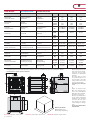 9
9
-
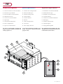 10
10
-
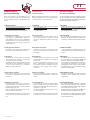 11
11
-
 12
12
-
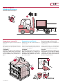 13
13
-
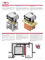 14
14
-
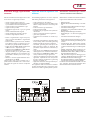 15
15
-
 16
16
-
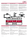 17
17
-
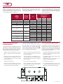 18
18
-
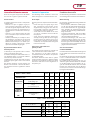 19
19
-
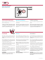 20
20
-
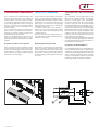 21
21
-
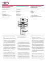 22
22
-
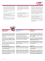 23
23
-
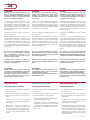 24
24
-
 25
25
-
 26
26
-
 27
27
-
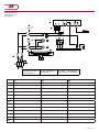 28
28
-
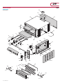 29
29
-
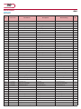 30
30
-
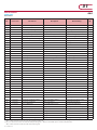 31
31
-
 32
32
-
 33
33
-
 34
34


Diamond G18-33 User and Installation Manual
- Categoria
- Forni
- Tipo
- User and Installation Manual
in altre lingue
- English: Diamond G18-33
- Deutsch: Diamond G18-33
Altri documenti
-
GGM Gastro GEP4#GEP4 Manuale del proprietario
-
Casselin CBMES75 Manuale utente
-
Univex Double Rack Rotating Manuale del proprietario
-
Bartscher 113085 Manuale del proprietario
-
Hendi 225516 Manuale utente
-
Falmec CLGN90.E0P2#ZZZI461F Scheda dati
-
-
Lotus NG-UA-005G Instructions For Use And Maintenance Manual
-
Candy FLG 203 X Manuale utente
-
Hoover HPG390/1X Manuale utente