La pagina si sta caricando...

cod. +050000212 - rel. 1.2 - dated 04.05.2015
2
5
3
4
1
NO POWER
& SIGNAL
CABLES
TOGETHER
READ CAREFULLY IN THE TEXT!
ATTENZIONE: separare quanto più possibile i cavi delle sonde e degli ingressi digitali dai cavi dei carichi
induttivi e di potenza per evitare possibili disturbi elettromagnetici. Non inserire mai nelle stesse canaline
(comprese quelle dei quadri elettrici) cavi di potenza e cavi di segnale.
WARNING: separate as much as possible the probe and digital input signal cables from the cables carrying
inductive loads and power cables to avoid possible electromagnetic disturbance. Never run power cables
(including the electrical panel wiring) and signal cables in the same conduits.
AVVERTENZE IMPORTANTI: Il prodotto CAREL è un prodotto avanzato, il cui funzionamento è specifi cato
nella documentazione tecnica fornita col prodotto o scaricabile, anche anteriormente all’acquisto, dal sito
internet www.Carel.com.
Il cliente (costruttore, progettista o installatore dell’equipaggiamento fi nale) si assume ogni responsabilità
e rischio in relazione alla fase di confi gurazione del prodotto per il raggiungimento dei risultati previsti in
relazione all’installazione e/o equipaggiamento fi nale specifi co. La mancanza di tale fase di studio, la quale
è richiesta/indicata nel manuale d’uso, può generare malfunzionamenti nei prodotti fi nali di cui CAREL non
potrà essere ritenuta responsabile. Il cliente fi nale deve usare il prodotto solo nelle modalità descritte nella
documentazione relativa al prodotto stesso. La responsabilità di CAREL in relazione al proprio prodotto è
regolata dalle condizioni generali di contratto CAREL editate nel sito www.Carel.com e/o da specifi ci accordi
con i clienti.
IMPORATNT WARNINGS: The CAREL product is a state-of-the-art device, whose operation is specifi ed in the
technical documentation supplied with the product or can be downloaded, even prior to purchase, from the
website www.carel.com. The customer (manufacturer, developer or installer of the fi nal equipment) accepts
all liability and risk relating to the confi guration of the product in order to reach the expected results in
relation to the specifi c installation and/or equipment. The failure to complete such phase, which is required/
indicated in the user manual, may cause the fi nal product to malfunction; CAREL accepts no liability in such
cases. The customer must use the product only in the manner described in the documentation relating to the
product. The liability of CAREL in relation to its products is specifi ed in the CAREL general contract conditions,
available on the website www.carel.com and/or by specifi c agreements with customers.
Smaltimento del prodotto: l’apparecchiatura (o il prodotto) deve essere oggetto di raccolta separata in
conformità alle vigenti normative locali in materia di smaltimento
Disposal of the product: the appliance (or the product) must be disposed of separately in accordance with
the local waste disposal legislation in force.
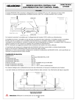
Elenco materiale
1. Modem GSM Sierra Wireless AirLink serie FXT;
2. alimentatore 100-240 Vac, 50/60 Hz;
3. antenna GSM 850-1900 MHz con 3 mt cavo RG174 e base magnetica;
4. antenna GSM 850-1900 MHz stilo orizzontale;
5. adattatore seriale/Ethernet™
6. cavo seriale standard RS232 15/9 pin (non in foto);
7. cavo USB standard (non in foto);
8. staff e di fi ssaggio (non in foto).
Attenzione: per una descrizione del prodotto e la guida completa
all’installazione si prega di fare riferimento alla documentazione disponibile
sul sito del produttore (www.sierrawireless.com).
Inserimento SIM card
1. Inserire la carta SIM nell’alloggiamento del modem rispettando la corret-
ta posizione, vedi fi gura sottostante:
2. spingere la carta SIM all’interno del modem fi no a sentire un click;
3. spostare l’interruttore di bloccaggio della SIM in posizione chiusa.
Attenzione: per estrarre la carta SIM utilizzare un utensile per spingere la
carta SIM fi no a sentire un click e rilasciare.
Collegamento antenna
1. Inserire l’antenna (inclusa) nel connettore RF principale del modem;
2. avvitare facendo attenzione a non stringere troppo.
Attenzione: l’antenna deve stare in posizione vericale (verso l’alto).
Collegamento seriale
(per dispositivi diversi da PlantWatchPRO3)
1. Inserire il cavo seriale (incluso) nel connettore SUB-DB15 del modem;
2. avvitare le viti di bloccaggio del connettore.
(solo PlantWatchPRO3)
1. Collegare il adattatore seriale/Ethernet™ al modem GSM;
2. collegare il modem GSM al PlantWatchPRO3 attraverso un cavo Ethernet™.
Alimentazione elettrica
1. Inserire il cavo di alimentazione (incluso) nel connettore 10-pin Micro Fit
del modem;
2. accendere la sorgente esterna di alimentazione elettrica.
Verifiche
1. Verifi care che il led del modem lampeggi lentamente;
2. per dispositivi diversi da PlantWatchPRO3: collegare ad un PC e verifi care
la comunicazione inviando comandi AT (vedere sezione “Test del modem
tramite un personal computer”).
3. solo per PlantWatchPRO3: verifi care che i led del connettore e della porta
Ethernet™ del PlantWatchPRO3 lampeggino.
Nota: per il collegamento al PC è possibile utilizzare il cavo USB incluso
ma è necessario installare sul PC i driver disponibili sul sito del produttore
(www.sierrawireless.com).
List of materials:
1. GSM Sierra Wireless AirLink series FXT modem;
2. power supply 100-240 Vac, 50/60 Hz;
3. GSM 850-1900 MHz antenna with 3 m RG174 cable and magnetic base;
4. GSM 850-1900 MHz Antenna horizontal stilo;
5. Serial/Ethernet™ adapter;
6. standard serial cable RS232 15/9 pin (not present in photo);
7. USB standard cable (not present in photo);
8. fi xing brackets (not present in photo).
Important: for the product description and complete installation
guide, see the documents available on the manufacturer’s website (www.
sierrawireless.com).
SIM Card insertion
1. Insert the SIM card in the slot on the modem, making sure it’s the right
way round, reff erring to following fi gure;
2. push the SIM card into the modem until it clicks into place;
3. move the SIM locking switch to the closed position. Important: to re-
move the SIM card, use a tool to press the SIM card in until it clicks out.
Antenna connection
1. Connect the antenna (included) to the main RF connector on the modem;
2. screw it on, making sure not to over-tighten.
Important: the antenna must be vertical (facing upwards).
Serial connection
(for devices diff erent from PlantWatchPRO3)
1. Connect the serial cable (included) to the SUB-DB15 connector on the
modem;
2. tighten the connector locking screws.
(only for PlantWatchPRO3)
1. Connect the serial/Ethernet™ adapter to the modem GSM;
2. Connect the modem GSM to the PlantWatchPRO3 with a Ethernet™ cable.
Power supply
1. Connect the power cable (included) to the 10-pin Micro Fit connector
on the modem;
2. Switch on the external power source.
Checks
1. Make sure that the LED of the modem fl ashes slowly;
2.
for devices diff erent from
PlantWatchPRO3: Connect to a PC and check
communication by sending AT commands (see the section on “Modem
test through a personal computer”).
3. only for PlantWatchPRO3: check if the LEDs of serial/Ethernet™ adapter
and Ethernet™ port, are fl ashing.
Note: the USB cable included can be used for PC connection, however
the driver available at the manufacturer’s website (www.sierrawireless.com)
must be installed).
Guida all’installazione del modem GSM Sierra Wireless AirLink serie FXT /
Installation manual for GSM Sierra Wireless AirLink series FXT modem

Lista comandi AT /
AT command list
Per ogni altra funzione, utilizzo e impostazione si rimanda alla lettura del manuale comandi AT o alla tab. 1.
Azione Comando Risposta
lettura campo AT + CSQ +CSQ: xx,yy
lettura operatore AT + COPS? COPS: 0,2,num. operatore
lettura centro servizi per sms AT + CSCA? CSCA: num. centro servizi
chiamata dati ATD numero connect
chiamata voce ATD numero OK
risposta a “ring” ATA OK
settaggio vel. seriale AT + IPR=velocità OK
salvataggio parametri modif. AT & W OK
trasmettere SMS AT + CMGS= num. destinatario > (prompt per il messaggio)
scrivere SMS > “ciao come stai” Ctrl Z OK
leggere SMS AT+GMGR=num. SMS notifi cato con GMTI: x “ciao come stai”
cancellare SMS AT + CMGD= num. SMS notifi cato OK
Tab. 1
For any other function, use and setting refer to the reading of the AT command manual.
Action Command Answer
read fi eld AT + CSQ +CSQ: xx,yy
read provider AT + COPS? COPS: 0,2, provider number
read sms service centre AT + CSCA? CSCA: service centre number
data call ATD number connect
voice call ATD number; OK
“ring” answer ATA OK
set serial speed AT + IPR= speed OK
save modifi ed parameter AT & W OK
send SMS AT + CMGS= addressee number > (message prompt)
write SMS > “hi, how are you” Ctrl Z OK
read SMS AT + GMGR= SMS number notifi ed by GMTI:x “hi, how are you”
erase SMS AT + CMGD= notifi ed SMS number OK
Tab. 1
cod. +050000212 - rel. 1.2 - dated 04.05.2015
CAREL INDUSTRIES HQs
Via dell’Industria, 11 - 35020 Brugine - Padova (Italy) - Tel. (+39) 0499716611
Fax (+39) 0499716600 - e-mail: carel@carel.com - www.carel.com
Configurazione modem per PlantWatchPRO3 /
Modem configuration for PlantWatchPRO3
Azione /
Action
Comando /
Command
Risposta /
Answer
Lettura IP corrente /
Current IP
*P=FXT009* GETIP GETIP - Sat 01/01/2000 03:48:28 - DHCP=F IPADDRESS=”192.168.1.2” SUBNETMASK=”255.255.255.0” GATEWAY=”0.0.0.0”
Settaggio IP /
Set IP
*P=FXT009* SETIP DHCP=F IPADDRESS=”192.168.1.2” SUBNETMASK =”255.255.255.0” GATEWAY=”0.0.0.0” SETIP - Sat 01/01/2000 03:54:05 - Confi guration accepted
Lettura credenziali connessione PPP /
PPP Login
*P=FXT009* GETPPPLOGIN GETPPPLOGIN - Sat 01/01/2000 02:52:20 - USER=”PVRemote” PWD=”PD35010”
Settaggio credenziali connessione PPP/
Set PPP Login
*P=FXT009* SETPPPLOGIN USER=”PW3” PWD=”CAREL” SETPPPLOGIN - Sat 01/01/2000 04:10:02 - Confi guration accepted
Lettura IP PEER corrente /
Current PEER IP
*P=FXT009* GETPEER GETPEER - Sat 01/01/2000 04:12:59 - PEERIPADDRESS=”192.168.1.1”
Settaggio IP PEER /
Set PEER IP
*P=FXT009* SETPEER PEERIPADDRESS=”192.168.1.1” SETPEER - Sat 01/01/2000 04:17:13 - Confi guration accepted
Password Corrente /
Current Password
*P=FXT009* GETPWD GETPWD - Sat 01/01/2000 03:01:02 - PWD=”FXT009” ENABLE=T SMSSENDER=T
Inserimento nuova Password /
Set New Password
*P=FXT009* SETPWD PWD=”123456789” ENABLE=T SMSSENDER=T SETPWD - Sat 01/01/2000 08:00:52 - Confi guration accepted
Reset Confi gurazione /
Confi guration Reset
*P=FXT009* DEFAULT DATA=”CONFIGURATIONS” DEFAULT - Sat 01/01/2000 03:19:48 - COMMAND EXECUTED - “DEFAULT DATA=”ALL””
Tab. 2
Imposazioni Default / Default settings
Note: Ai fi ni della sicurezza del sistema si raccomanda di cambiare le password di default. / For safety reasons we strictly recommend to change the default passwords.
Note: Requisiti per la PASSWORD MODEM /
PASSWORD MODEM requirements
:
• stringa alfanumerica (solo i caratteri a-z, A-Z, 0-9 sono permessi)/
alphanumeric string (only a-z, A-Z, 0-9 characters allowed)
• non sensibile alle maiuscole /
case-insensitive
• lunghezza minima /
minimun length
: 6
• lunghezza massima /
maximum length
: 14
PASSWORD MODEM FXT009
Connessione PPP/PPP connection Username = PVRemote
PASSWORD = 35010
Indirizzo IP / IP Address 192.168.1.2
Collegamento ai prodotti Carel
(per dispositivi diversi da PlantWatchPRO3)
Collegare il lato maschio 15 poli al modem GSM ed il lato 9 poli femmina al PC
o ad un cavo seriale standard. Inoltre:
• per PlantVisorPRO2 installare il modem selezionando il driver “Modem
standard 19200 bps”. Quindi impostare il campo “Maximum Port Speed” a
115200 nel tab “Modem” delle “Properties” del modem stesso;
• per pCO usare l’opportuna scheda seriale RS232 e programmare il modem
a 9600.
(solo per PlantWatchPRO3)
Usare il adattatore seriale/Ethernet™ per collegare il modem al PlantWatchPRO3,
quindi confi gurare il modem attraverso invio sms seguendo la tabella 2 o la
guida presente sul sito ksa (http: ksa.carel.com/).
Test del modem tramite un personal computer
(per dispositivi diversi da PlantWatchPRO3)
Predisporre il PC con un programma di emulazione terminale es. Hyper
Terminal di Windows confi gurato nel seguente modo:
velocità di linea 115200 bit/s
parità nessuna
bit dati 8
bit stop 1
controllo di fl usso nessuno
Per verifi care il corretto collegamento e impostazione della porta dare il co-
mando “AT” invio e ricevere “OK”.
Carel product connection
(for devices diff erent from PlantWatchPRO3)
Connect the 15-pole male side to the GSM modem and the 9-pole female
side to the pc or to a standard serial cable. Otherwise:
• for PlantVisorPRO2 fi t the modem selecting the driver “Modem standard
19200 bps”. Then, set the fi eld “Maximum Port Speed” to 115200 in the
“Modem” tab of modem “Properties”;
• for pCO use the dedicatd RS232 serial card and fi t the modem using 9600
bps modem drive.
(only for PlantWatchPRO3)
Use the serial/Ethernet™ adapter to connect the modem to PlantWatchPRO3,
then confi gure the modem by sending sms, as described on table 2, or in the
guide on ksa site (http: ksa.carel.com/).
Modem test through a personal computer
(for devices diff erent from PlantWatchPRO3)
Prearrange the PC with a terminal emulation program for ex. Windows
Hyper Terminal confi gured as the following:
line speed 115200 bit/s
parity none
data bits 8
stop bit 1
fl ow control none
To check the right connection and setting of the door, press “AT” enter and
receive “OK”.
Carel si riserva la possibilità di apportare modifi che o cambiamenti ai propri
prodotti senza alcun preavviso.
Carel reserves the right to modify the features of its products without prior
notice.
1/2