Jamara 053270 Istruzioni per l'uso

Categoria
Giocattoli telecomandati
Tipo
Istruzioni per l'uso
13/22
Frequency bands: 2.4Ghz Frequency range: 2405,5 MHz - 2475,0 MHz EIRP: 49,09 mW (max. power transmitted)
Splinter EP | BL
2,4 GHz
No. 053270 EP
No. 053271 EP LiPo
No. 053275 BL LiPo
IT - Istruzioni di montaggio
GB - Instruction
Dichiarazione di conformità
Con la presente JAMARA e.K. dichiara che i prodotti „Splinter EP | BL 2,4 GHz, No. 053270,
No. 053271, No. 053275“ è conforme alla Direttiva 2014/35/UE, 2014/53/UE e
2011/65/UE.
Il testo integrale della dichiarazione di conformità UE è disponibile al seguente
indirizzo Internet: www.jamara-shop.com/Conformity
Certicate of Conformity
Hereby JAMARA e.K. declares that the products „Splinter EP | BL 2,4 GHz, No. 053270,
No. 053271, No. 053275“ comply with Directives 2014/35/EU, 2014/53/EU and 2011/65/EU.
The full text of the EU Declaration of Conformity is available at the following Internet address:
www.jamara-shop.com/Conformity
Informazioni generali
JAMARA e. K. non e´responsabile per danni, sostenute al prodotto stesso o attraverso questo,
dovuti ad una gestione non corretta del articolo. Solo il cliente si assume la piena responsabilità per
la manutenzione e l´utilizzo corretto dello stesso; questo include il montaggio, la ricarica, l´utilizzo,
 no alla scelta della aerea di applicazione. Si prega di notare e rispettare le istruzioni d´uso, questi
contengono informazioni e avvertimenti molto importanti
General information
Jamara e.K. is not liable for any damage caused to the product itself or through this, provided this
is due to improper operation or handling errors. The Customer alone bears the full responsibility for
the proper use and handling, including without limitation, the assembly, the charging process, the
use and choice of the operation area. Please refer to the operating and user instructions, it contains
important information and warnings.
Attenzione!
Prima dell‘uso: Accendete prima la trasmittente e poi il modello.
Dopo l‘uso: Spegnere prima il modello e poi la trasmittente.
Non utilizzare il suo modello fuori della distanzia di vista. Sia la visibilità come la portata
massima del vostro modello dip endono da molti fattori, come il tempo, disturbo di frequenza e il
luogo di utilizzo. Eseguire un test prima di ogni utilizzo del modello con una seconda persona
che tiene ssato il modello. Con questa procedura potete testare come reagisce il modello
durante la perdita del segnale ca usato per esempio da una batterie scarica oppure la radio
spenta.
Attention!
Before operating: Switch the transmitter on rst then the model.
When nished: First switch o the model then the transmitter.
Never operate your model beyond sight. Both the maximum visibility as well as the max. range
of your model will depend on many factors such as weather, location and interfering
frequencies. Therefore, before each use perform a range test with a second person securely
holding the model and also check how the model reacts if there is a signal failure e.g. when
empty transmitter batteries are installed.
Questo modello non é un giocattolo!
Attenzione: Non adatto a bambini di età inferiore a 36 mesi.
RISCHIO DI SOFFOCAMENTO!
Contiene piccoli pezzi che possono essere ingeriti.
Tenere sempre fuori dalla portata dei bambini.
This model is not a toy!
Warning: Not suitable for children under 36 months.
RISK OF SUFFOCATION!
Contains small parts which can be swallowed.
Keep away necessarily from children.
Accessori consigliati Recommended Tool
Prima di avviare il modello, leggere attentamente tutte le istruzioni per l’uso.
Attenzione! Leggere completamente le avvertenze / istruzioni di sicurezza, questi
sono per la vostra sicurezza può prevenire incidenti / infortuni.
Read the complete instructions and security instructions carefully before using the model.
Caution! Please fully and carefully read warnings/ safety instructions. These are for
our own security and can avoid accidents/injuries.
Questo prodotto è un articolo di modellismo. Ciò signica che il veicolo deve essere sempre sotto-
posto a manutenzione (controllare eventuali danni, controllare i collegamenti a vite, pulire ecc...).
Le parti soggette ad usura come l‘ingranaggio principale, il pignone del motore, bicchierino ecc.
si consumano nel tempo e devono pertanto essere sostituite. Non è sempre possibile evitare gli
incidenti, pertanto è necessario riparare o sostituire anche i danni causati dagli incidenti. Le parti
usurate o difettose a causa di urti o manutenzione insuciente non sono coperte da garanzia, i costi
e le riparazioni sono a carico dell‘acquirente stesso.
This product is a model building article. This means that the vehicle must always be serviced (check
for damage, check screw connections, clean etc...). Wear parts such as the main gear, motor pinion,
bone socket, etc. will wear out over time and must therefore be replaced. Crashes cannot always be
avoided, so crash damage must also be repaired or replaced. Wear parts or defective parts due to
crashes or insucient maintenance are not covered by warranty, costs and repairs must be covered
by the buyer himself.
No. 190065
Misuratore convergenza
Camber adjusting Tool
No. 232060
Power Tape silicone
Doublesided power tape
No. 232423 medium
Lacca protezione
Nut lock
No. 281730
Forbici per lexan
Lexan scissors
No. 059273 1:10
Graette per carrozzeria
Body clips
No. 505401 piccolo/small
Graette per carrozzeria
Body clips
No. 153059
X-Peak 80 V2
Caricatore
Charger
2
NiMh
1
Version 053270
2
3
4
5
6
8
8
7
Lieferumfang
1. Modello
2. Telecomando
3. Antenna
4. Clip per precarico molla
5. Connettore di collegamento
6. Batteria LiPo (053271/053275)
7. Caricatore LiPo
8. Batteria NiMh (053270)
9. Caricatore USB NiMh
Accessori:
Telecomando: 4 x AA 1,5V,
No. 140267 (4 pezzi)
Dati tecnici:
• Dimesioni:
~ 410 x 270 x 156 mm
Peso:
~ 2519,4g (No. 53270/053271)
~ 2430,2g (No. 053275)
• Batteria:
NiMh 7,2 V 2000 mAh
(No. 053270)
LiPo 7,4 V 5000mAh
(No. 053271 / 053275)
• Motore:
270 W
(No. 053270 / 053271)
420 W 3200 KV
(No. 053275)
Le informazioni non sono
garantite. Ci riserviamo il diritto di
apportare modiche tecniche e la
possibile presenza di errori.
Box contents
1. Model
2. Transmitter
3. Antennas
4. Clip for spring tension
5. Binding Plug
6. Battery LiPo (053271/053275)
7. Charger LiPo
8. Battery NiMh (053270)
9. USB-Charger NiMh
Accessories:
Transmitter: 4 x AA 1,5V,
No. 140267 (4 pieces)
Technical data:
• Dimensions:
~ 410 x 270 x 156 mm
• Weight:
~ 2519,4g (No. 53270/053271)
~ 2430,2g (No. 053275)
• Battery:
NiMh 7,2 V 2000 mAh
(No. 053270)
LiPo 7,4 V 5000mAh
(No. 053271 / 053275)
• Motor:
270 W
(No. 053270 / 053271)
420 W 3200 KV
(No. 053275)
No responsibility is taken for the
correctness of this information.
Primi passi - Processo di ricarica Getting Started - Charging process
NiMh Processo di ricarica (053270)
Collegare il caricatore USB a una porta USB. Raccomandiamo un adattatore di rete USB (2A)
per la presa di corrente. Le connessioni USB di computer e portatili di solito non possono fornire
corrente suciente per caricare la batteria. Il LED sul caricatore si illumina di verde. Collegare il
caricatore USB alla batteria NiMh. Il LED rosso del caricatore USB segnala il processo di ricarica.
Se la spina del caricatore e la spina della batteria di trazione non corrispondono, un adattatore di
ricarica è incluso nel vostro modello. Quando la batteria è completamente carica, il LED si illumina
di verde. Assicuratevi assolutamente che il tempo di ricarica non venga superato. Non caricare bat-
terie diverse dalla batteria NiMh in dotazione. Il tempo medio di ricarica per la batteria NiMh vuota
in dotazione è di circa 6 - 8 ore.
Se il LED lampeggia, c‘è un guasto. Si prega di contattare il servizio clienti.
Attenzione:
Caricare solo le batterie adatte con questo caricabatterie. Le batterie adatte sono batterie al nichel-
metallo idruro con max. 6 celle, max. 7,2 V di tensione nominale e massimo 2000 mAh. La batteria
deve avere un connettore Tamiya. Caricare batterie non adatte può danneggiare il caricatore e
la batteria. Pericolo di incendio! Il collegamento di carica del caricabatterie non deve mai essere
saldato o modicato!
NiMh Charging process (053270)
Connect the USB charger to a USB port. We recommend a USB adapter (2A) for the grounding
receptable. USB ports of computers and laptops usually cannot provide sucient current to charge
the battery. The LED on the charger lights up green. Connect the USB charger to the NiMh drive
battery. The red LED of the USB charger signals the charging process. If the plug of the charger and
the plug of the drive battery do not match, a charging adapter is included with your model. When the
battery is fully charged, the LED lights up green. Make absolutely sure that the charging time is not
exceeded. Do not charge any batteries other than the NiMh battery supplied. The average charging
time for the empty NiMh battery supplied is approx. 6 - 8 hours.
If the LED ashes, there is a fault. Please contact the customer service.
Caution:
Only charge suitable battery‘s with this charger. Suitable battery‘s are Nickel metal hydride battery‘s
with max. 6 cells, max. 7,2 V nominal voltage and max. 2000mAh. The battery must have a tamiya
plug. The charging of unsuitable battery‘s can cause damage to the charger and the battery‘s.
Fire Hazard! The charging connection of the charger is not allowed to get altered or soldered to a
dierent balancer plug type!
Avete acquistato un modello RTR. Ciò signica che il veicolo è in gran parte pronto per l‘uso
immediato. Tuttavia, è essenziale controllare che il modello non presenti possibili danni
meccanici o elettrici o difetti prima e dopo ogni utilizzo. È inoltre necessario vericare la
libertà di movimento di tutti gli elementi mobili e la tenuta dei collegamenti a vite.
You have purchased a RTR model, which means it should be ready for immediate use after
charging all batteries. You need to check the car, electronics and all plastic parts after each
use to make sure no parts are damaged. Also all the moving parts must be checked for their
clearance, bolts and screws that they are tight.
LiPo Processo di ricarica (053271 / 053275)
Note importanti sull‘idoneità della batteria:
Assicurarsi di utilizzare solo batterie ai Polimeri di Litio con connettore XH balancer. Solo queste
possono essere utilizzate con il caricatore. Altri collegamenti e tipi di batterie non possono essere
utilizzati (si può vericare il rischio di incendio dovuto all‘inversione di polarità o al sovraccarico).
Si prega di contattare il produttore della vostra batteria per sapere se la vostra batteria è adatta. Uti-
lizzare solo batterie LiPo con una capacità di almeno 1600mAh (altrimenti c‘è il rischio di incendio
a causa della corrente di carica eccessiva). Se si utilizzano batterie con una capacità inferiore a
1600mAh, le batterie devono essere approvate per una corrente di carica di 1600mA (carica rapida).
Si prega di chiedere al produttore della vostra batteria se la vostra batteria soddisfa questi requisiti.
È possibile collegare solo una singola batteria alla volta al caricatore. Caricare 2 batterie
allo stesso tempo NON è permesso e causerà danni alla batteria o al caricatore (pericolo di
incendio).
LiPo Charging process (053271 / 053275)
Important notes on the suitability of the battery:
Make sure to use only lithium polymer batteries with XH balancer connector. Only these may
be used with the charger. Other connections and battery types must not be used (re hazard due to
reverse polarity or overcharging may result).
Please contact the manufacturer of your battery to nd out whether your battery is suitable. Only
LiPo batteries with a capacity of at least 1600mAh must be used (otherwise there is a risk of
re due to excessive charging current). If you use batteries with a capacity below 1600mAh, the
batteries must be approved for a charging current of 1600mA (Speedcharging). Please ask the
manufacturer of your battery if your battery meets these requirements.
You may only connect one single battery to the charger at a time. Charging 2 batteries at
the same time is NOT allowed and will cause damage to the battery or charger (re hazard).
Solo per / Only for:
Version 053271
Version 053275
Solo per:
Only for:
Version 053270
1 2 3
4
3
4x AA
1 2
IT
1. Ingresso 100 - 240 V
2. Attacchi di bolanciatore 2 cella
3. Attacchi di bolanciatore 3 cella
(Non richiesto per questo modello)
4. LED di stato
GB
1. Power Slot 100 - 240 V
2. 2S Balancer
3. 3S Balancer
(Not required for this model)
4. Status LEDs
LiPo Caricare una batteria
1. Inserire il cavo di alimentazione del caricabatterie in una presa adatta. I LED si illuminano di
verde e indicano che la batteria è pronta per la ricarica
2. Ora collega la batteria vuota al caricatore. Batterie 2S da 7,4V al connettore a 3 poli o 11,1V
batterie 3S al connettore a 4 poli. Non usare la forza e fare attenzione a non invertire la polarità.
I LED diventeranno rossi dopo pochi secondi, indicando che le celle della batteria si stanno
caricando.
Attenzione!
Quando si collega una batteria 2S, solo i primi 2 LED (Cell1-2) diventano rossi, il LED 3
(Cell 3) rimane verde. Quando si collega una batteria 3S, tutti i LED (Cell1-3) diventano
rossi.
Non appena una cella della batteria è completamente carica, il LED corrispondente diventa
verde. Poiché le celle sono caricate individualmente, è possibile che una cella sia
completamente carica prima delle altre, a seconda dello stato della batteria. Lasciare sempre la
batteria sul caricatore no a quando tutte le celle collegate sono completamente cariche (verde)
per permettere al caricatore di bilanciare la batteria.
Charging a battery
1. Plug the power cord of the charger into a suitable socket. The LEDS light up green and indicate
that the charger is ready for charging.
2. Now connect the empty battery to the charger. 7.4V 2S batteries to the 3 pin connector or 11.1V
3S batteries to the 4 pin connector. Do not use force and pay attention to reverse polarity. The
LEDs change to red after a few seconds and indicate that the battery cells are charging.
Attention:
When connecting a 2S battery, only the rst 2 LEDs (Cell1-2) change to red, LED 3 (Cell 3)
will remain green. When 3S batteries are connected, all LEDs are red (Cell1-3).
As soon as a the battery cell is full, the corresponding LED changes to green. Because the cells
are charged individually in a balanced way, it is possible that one cell is fully charged earlier than
the others. Always leave the battery on the charger until all connected cells are fully charged
(green) to allow the charger to balance your battery
Riconoscimento di una batteria carica.
Quando si collega una batteria carica al caricatore, i LED diventeranno rossi per alcuni secondi e poi
torneranno verdi. Questo signica che la batteria è già completamente carica.
Riconoscimento di una batteria difettosa.
Se i LED rimangono verdi quando si collega una batteria vuota, c‘è un difetto nella batteria (difetto
della cella o scarica profonda). In questo caso, scollegare immediatamente la batteria dal caricatore
e utilizzare un‘altra batteria.
Detecting a full battery.
When you connect a full battery to the charger, the LEDs will turn red for a few seconds and then
turn green again. This means that the battery is already fully charged.
Detecting a defective battery.
If the LEDs remain green when an empty battery is connected, there is a defect in the battery (cell
defect or deep discharge). In this case, immediately disconnect the battery from the charger and
use another battery.
Montaggio delle batterie nel trasmettitore
Inserire 4 batterie AA nella trasmittente.
Inserting batteries into the transmitter
Put 4 AA Batteries into the Transmitter
Informazioni relative alle pile:
Le batterie non ricaricabili non devono essere caricate!
Non aprire!
Non gettare nel fuoco!
Non usare contemporaneamente pile nuove e pile usate!
Non usare contemporaneamente pile alcaline, standard (zinco-carbone) e ricaricabili!
Le batterie ricaricabili devono essere rimosse dal giocattolo!
Le batterie ricaricabili possono essere ricaricate solo sotto la supervisione di un adulto!
I morsetti di collegamento don devono essere cortocircuitati!
Battery warning:
Non-rechargeable batteries are not to be recharged!
Do not open!
Do not dispose of in re!
Do not mix old and new batteries!
Do not mix alkaline batteries, standard (carbon-zinc) or rechargeable batteries!
Rechargeable batteries are to be removed from the toy before being charged!
Rechargeable batteries are only to be charged under adult supervision!
The supply terminals are not to be short-circuited!
Attenzione!
Dopo ogni carica e importante di: Scollegare sempre subito la batteria dal caricatore
ed il caricatore dalla rete elettrica. Se dopo la carica si lascia collegato l’uno o l’altro
può causare danni alla batteria, al caricatore o addirittura alla rete elettrica (pericolo
di incendio).
Danger!
Always disconnect the battery from the charger immediately after charging. Always
disconnect the charger from the power supply immediately after disconnecting the
battery. Inserting the rechargeable battery or charger after charging will result in
damage to the battery, charger or the power supply (re hazard).
4
505080
505081
07 9996
505079
505080
505081
079996
505079
ON/OFF
1
Attenzione!
Il veicolo è dotato di una Pivot sospensione anteriore. Questa
ha una serie di vantaggi. E ‚molto robusta e la manutenzione
e´molto facile. Questo è impostato in fabbrica in modo che la
carreggiata non permette agli cardani di saltare fuori. Come con
qualsiasi modello, dopo l´inizio dell’uso si rallentano di qualche
millimetro sia la sospensione sia i bulloni. Questo gioco minimo,
po’ abbastare sotto massimo sforzo per fare saltare fuori i car-
dani. Pertanto è necessario per assicurarsi prima di ogni uso
che tutte le viti, dadi, giochi ecc., sono ssate correttamente. La
vita esterna in plastica 505080 serva per ssare il fuso a snodo
sulla vite a sfera. Questo non deve essere serrata troppo forte.
In caso contrario, lo sterzo non si muove liberamente e la guida
può essere inuenzata negativamente.
Attention!
Your vehicle has a pivot front suspension. This has a number of
advantages. It is very robust and easy to maintain. The set-up of
the car has been done so the drive shaft will not pop out. As with
any model, screws and bolts can losen during break-in of the
car. This can result in tolerance of the drive shaft. The drive shaft
can then pop out if high pressure is applied. The inner ball screw
(item No.: 505081) will enable you to adjust the tolerance resul-
ting in ne adjustments of the track width. For best results when
setting up the pivot ball for the rst time, please always adjust
the upper and lower pivot in the same way. Fasten as far as the
pivot can still be pulled up and down easyly but not as far that it
will pop out if you give full steering angle. The outer plastic socket
screw (item No.: 505080) is only used for securing of the steering
knuckle. This should not be too tight, otherwise the steering is
not smooth and the handling can be adversely aected.
Attenzione!
Il giunto omocinetico anteriore e posteriore assorbe la maggior
parte dell’energia del motore e lo passa all’asse anteriore e
posteriore. Per questo, le vite a brugola che tengono il giunto
omocinetico sul asse di uscita prima del primo utilizzo e
in intervalli regolari (5-7 inserti) devono essere controllati e
se necessario avvitare. Nel giunto omocinetico anteriore e
posteriore deve essere inserito un anello di gomma. Controllare
il gioco del albero motore. Il margine del gioco dovrebbe essere
di ca. 1-2 mm. Potrebbe essere necessario spostare il giunto
omocinetico per adattare il gioco. Qui deve svitare le vite senza
testa con un cacciavite e regolare il giunto omocinetico. Dopo di
che avvitare le vite senza testa. In caso contrario l’omocinetico
si sposta sul albero di uscita e l’omocinetico e l’albero centrale
possono essere danneggiati.
Attention!
The front and rear bone pan absorbs most of the motor‘s
energy and directs it to the front and rear axles. Therefore,
the hexagon socket screws which hold the bone pans on the
transmission output shafts must be checked and, if necessary,
tightened before the rst use and in regular intervals e.g 5-7
uses. Insert a rubber ring to the front and the back connection
cup. Please check the tolerance of the drive shaft. The tole-
rance should be approx. 1 – 2mm. You may have to move the
connection cups to adapt the tolerance. Therefore you need to
loosen the grub screws to adapt the connection cup.
Afterwards tighten the grub screws. If not, the connection cups
will move on the gear output shaft. That might cause the con-
nection cup and the middle drive shaft to get damaged.
Attenzione.
Spegnere sempre il modello subito dopo ogni utilizzo. Subito dopo ogni utilizzo,
la batteria deve essere scollegata dal modello. La batteria può essere scaricata
completamente se viene lasciata accesa accidentalmente o se viene lasciata in-
serita. La scarica profonda causa la perdita di energia della batteria o può essere
danneggiata a tal punto che la carica o la scarica non è più possibile o la batteria
può autoaccendersi durante la carica o la scarica (pericolo di incendio). Non ten-
tare mai di caricare o scaricare batterie completamente scariche. La tensione del-
la batteria LiPo non deve mai scendere sotto i 6 volt e quella della batteria NiMh
non deve mai scendere sotto i 4 volt per evitare una scarica profonda. La batteria
LiPo completamente carica ha una tensione di circa 8,4 volt e la batteria NiMh di
8,5 volt. Dopo l‘uso, le batterie intatte devono essere ricaricate completamente
subito dopo una fase di rareddamento di minimo 10 minuti e al più tardi dopo
12 ore per evitare una successiva scarica profonda per autoscarica. Se le batterie
non vengono utilizzate o conservate per un lungo periodo di tempo, è necessario
controllarne la tensione ossia il danneggiamento almeno ogni 3 mesi (con LiPo
minimo 8 Volt, con NiMh minimo 7,4 Volt) se necessario, ricaricarle o smaltirle.
Danger.
Always switch o the model immediately after each use. Immediately after each
use the battery should be disconnected from the model. The battery can be
deeply discharged by leaving it switched on accidentally or leaving it plugged
in. Deep discharge causes the battery to lose power or can be damaged to such
an extent that charging or discharging is no longer possible or the battery can
self-ignite during charging or discharging (re hazard). Never attempt to charge
or discharge deep-discharge batteries.
The voltage of the LiPo batteries should never be under 6 volt and the NiMh bat-
tery never under 4 Volt to avoid a depth discharge. The fully charged LiPo battery
has a voltage of approx. 8,4 Volt and the NiMH battery 8,5 Volt.
After usage, the intact battery has to be fully charged after a cooling phase of at
least 10 min but not longer than 12 hrs. This is to avoid a deep discharge caused
by a self-discharge. When not using or storing the battery´s it has to be checked
at least every three months for voltage (For LiPo min. 8 Volt, for NiMh min. 7,4
Volt.) or damage and if necessary charged or disposed.
Regolatore
ESC
Batteria
Battery
Collegamento della
regolatore/batteria
ESC/Battery connector
Inserire la batteria nel portabatteria del veicolo e fissarla con le cinghie in velcro.
Accertarsi che la batteria sia saldamente bloccata nel portabatteria senza troppi giochi.
Ora collegare la batteria con il regolatore del modello. Se la spina del regolatore e la spina
della batteria non corrispondono, un cavo adattatore è incluso con il modello.
Leggere il capitolo sulla trasmittente. Accendere la trasmittente e assicurarsi che i trim siano in
posizione neutrale
Tenere il modello in aria per il caso che il motore si metta a girare a tutto gas.
Ora accendere il regolatore di velocità tramite l`interruttore ON / OFF.
Vi incoraggio ad attivare il ricevitore integrato in unità fail-safe.
Al momento della consegna è spento.
Se questa è la tua prima auto rc, si consiglia di guidare su una pista piccola per familiarizzare
con il controllo del veicolo e i comandi del trasmettitore.
Put the battery into the battery holder in the vehicle. Make sure that the battery holder is scured
properly with the 2 included clips for the battery holder.
Now connect the battery to the speed control in the model. If the plug of the speed control and
battery do not match, then you will nd a connection lead in your box
Turn the radio on and make sure all the trim buttons on the transmitter are in neutral position.
Read the chapter for usage of the transmitter.
Keep the car in the air in case that the motor turns at full power.
Switch the speed control on the On / O switch.
We encourage you now to activate your receiver‘s built-in Failsafe unit.
On delivery it is turned o. (see chapter Fail Safe).
If this is your rst rc car, we recommend to drive it on a small test track to familiarise yourself
with the control of the vehicle and the controls of the transmitter.
Batteria/Battery
Regolatore
ESC
EIN/AUS
ON/OFF
5
C
A
B
D
E
G
H
F
I
6
12
3
4
5
Fail Safe
Setup LED
Programmazione del gruppo integrato di FailSafe
1. Descrizione della Funzione
L’unità FailSafe è concepita principalmente per l‘utilizzo sulle imbarcazioni e sui veicoli. Serve
per evitare la perdita del modello, determinando la chiusura del gas, nell’eventuale assenza
di segnale. Se la ricevente perde il segnale della trasmittente, il servo del gas o regolatore di
velocità ritorna automaticamente sulla posizion e programmata inizialmente.
2. Impostazione
a. Accendere la trasmittente
b. Accendere la ricevente. Il segnale LED lampeggia continuamente e indica che la ricevente
è pronta.
c. Spostare sul trasmettitore la leva dell‘acceleratore nella posizione di freno, o zona spento
nel regolatore di velocità. Tenere la leva del gas su questa zona.
d. Premere il pulsante Imposta sul ricevitore. Il segnale LED lampeggia per 3 secondi (vedi
illustrazione a sinistra).
e. L‘impostazione è salvata e si può portare la leva dell’acceleratore in posizione neutra.
3. Prova delle impostazioni
a. Accendere la trasmittente.
b. Accendere la ricevente.
c. Spegnere la trasmittente.
d. Ora la ricevente perde il segnale e conduce il servo del canale gas o il regolatore di
veloità sulla posizione in precedenza programmata.
e. Seguire la procedura descritta sopra, il processo FailSafe funziona correttamente.
How to setup the fail safe function
1. The instruction of function
The function of protection of losing control is mainly for r/c boats and cars and keeps them
away from damage through throttle channel. When the receiver is out of control signal, the
receiver of throttle will automatically return to the initial position which set up before starting to
avoid the error action :
2. How to set the function
a. Switch on the transmitter power and enter into the working condition
b. Connect the receiver with power and enter into the working condition, the signal light
on receivewill blink all the time.
c. Control the throttle of transmitter and keeps the servo or ESC in the neutral position.
d. Press the setting button, the LED will be ash for 3 seconds (see on pict. left).
e. Release the setting button. The setting is nished.
3. Testing
a. Switch on the transmitter and enter the working condition.
b. Contact the receiver with power and enter the working condition.
c. Turn o the power of transmitter.
d. The throttle of servo will be set automatically.
e. Finish these steps above means the setting is ok.
Trasmittente 2,4 GHz 2CH Transmitter 2,4 GHz 2CH
Vista laterale destra
1. Scatola di programmazione
2. Volante
3. Leva del gas
4. Vano batterie
5. Presa di carica
6. Collegamento per cavo simulatore
Se si carica attraverso una presa, si prega di
aprire il coperchio della batteria. Viene usato
per il rareddamento.
Settore di programmazione
A. Direzione reverse
B. Power LED
C. Direzione trim
D. Interruttore ON/OFF
E. Gas Reverse
F. Power Check
G. Pulsatne collegamen to binde
H. Dual-Rate
I. Gas Trim
Trim
Se le ruote non puntano dritti in avanti, anche
se il volante della trasmettente è in posizione
neutrale, è possibile ottenere aiuto con il trim
della trasmittente nella posizione corretta.
Trim L/R = Sterzo
Se le ruote girano in avanti o indietro, anche se
nessun comando è stato dato attraverso il tras-
mettitore, poi anch l‘acceleratore deve essere
tagliato sul trasmettitiore.
Trim V/R = Avanti/Indietro
Inserimento delle batterie
Togliere il coperchio del scomparto batterie.
Inserire 4 x AA batterie nella giusta
posizione, facendo attenzione ai poli.
Rimettere il coperchio del scomparto
batterie.
GB - Controls
1. Programming Box
2. Steering Wheel
3. Throttle Lever
4. Battery Hatch
5. Charge Socket
6. Simulator Cable Socket
If charging the batteries via the charging socket,
the battery hatch cover should be removed to
ensure sucient cooling.
Programming Panel
A. Steering Reverse (changed)
B. Power LED
C. Steering Trim
D. ON/OFF Switch
E. Throttle Reverse (changed)
F. Power Check
G. Binding Button
H. Dual-Rate (maximum steering deection)
I. Throttle Trim
Trim
If the wheels do not point straight forward even
though the steering wheel on the transmitter is
in neutral, you can adjust it with the trim button
on the transmitter.
Trim L/R = steering
Should the wheels rotate forward or backward,
even though no command was given through
the transmitter, then also the throttle needs to
be trimmed on the transmitter.
Trim V/R = forward/backward
Insert the batteries
Remove the battery compartment cover.
Fit the 4 x AA batteries, observe the correct
polarity.
Replace the battery hatch
2,4 GHz
Antenna
Antenna
Ricevente/Receiver
Allacciare la trasmittente alla ricevente
La ricevente accetta quindi solo i segnali della trasmittente. Se
per qualsiasi motivo si dovesse eetuare un nuovo allacciamento
„connessione“, eseguire le seguenti operazioni:
1. Sostituire nella trasmettente le batterie scariche con altre
cariche o nuove. Lasciare spenta la trasmettente.
2. Inserire la spina di accoppiamento in dotazione nell’uscita del
canale 3.
3. Collegando la batteria con la ricevente, si accende il sistema
ricevente. l Led sulla ricevente inizia lampeggiare e
cosisegnala che la ricevente si trova in modalità di binding.
4. Tenere premuto il pulsante di connessione sulla trasmittente,
mentre si accende la stessa. E. Il trasmittente inizia a
lampeggiare e cosi segnala che si trova in modalità di binding.
5. Rilasciare il pulsante di connessione della trasmettente e
rimuovere la spina di connessione nella ricevente. Spegnere
laricevente e la trasmittente.
6. Adesso spegnete la trasmittente. Il sistema memorizza il
collegamento.
7. Installare correttamente tutti gli accessori e controllare con
molta attenzione.
8. Se la funzione non avesse successo, ripetere la procedura di
connessione.
Vi incoraggiamo ora ad attivare l‘unità Failsafe incorporata del vos-
tro ricevitore. Alla consegna è spento.
Montare l‘antenna 2.4 GHz verticalmente come mostrato nel dia-
gramma. Non permettete a nessun oggetto metallico di entrare
in contatto con l‘antenna o di schermarla perché questo ridurrà
la portata.
Binding the receiver to the transmitter
In the delivery state, the transmitter is already bound to the re-
ceiver. If the model does not respond to the transmitter, try binding
it again.
For this purpose, proceed as follows:
1. Put the battery into the model.
Now connect the battery to the speed control in the model.
2. Plug the binding plug (included) into the channel 3 socket on
the receiver.
3. Switch the receiver system on. The receiver LED will begin to
ash indicating that the receiver is in bonding mode.
4. Press and hold down the binding button on the transmitter
whilst switching it on.
5. The transmitter will begin to ash indicating that the receiver
is in bonding mode.
5. Release the binding button on the transmitter and turn o the
controller. Release the binding plug from the receiver.
7. Switch of the transmitter. And remove the binding wire. The
system be bound at the next start .
8. If the receiver fails to bond or does not function after bond-
ing repeat the above procedure until a successful bonding is
achieved.
We encourage you now to activate your receiver‘s built-in Failsafe
unit. On delivery it is turned o.
Mount the 2.4 GHz antenna vertically as shown in the diagram. Do
not allow any metal object to come into contact with the antenna or
to shield it as this will reduce the range.
Connettore di
collegamento
Binding Plug
6
Attacco per la batteria
Battery connector
Cavo di allacciamento del regolatore
Signal wire
Pulsante on/o
On/O switch Attacco per la motore
Motor connector
Attacco per la motore
Motor connector
IT - Regolatore (installato) Versione EP
Dati technici:
Voltaggio 7,2 - 7,4 V
Batterie 2 Lipo | 6 NiCd/NiMh celle
Resistenza interna Fwd: 0.002 Ohm, Bwd: 0.004 Ohm
Tensione BEC BEC 2A/5V (Linear mode BEC)
Uso RC-Car 1:10
Protezione Sottotensione
Carico continuo 40 A
Dimensioni ~ 45 x 32 x 26 mm
GB - Controller (installed) Version EP
Technical Data:
Operating Voltage 7,2 - 7,4 V
Battery Pack 2 Lipo | 6 NiCd/NiMh Cells
Internal Resistance Fwd: 0.002 Ohm, Bwd: 0.004 Ohm
BEC Voltage BEC 2A/5V (Linear mode BEC)
Intended use RC-Car 1:10
Protection Circuit Under voltage cut o
Continuous load 40 A
Size ~ 45 x 32 x 26 mm
Se si utilizza una batteria Lipo, é necessario attivare il Lipomodo attraverso il Jumper (con-
nessione ponticello). Prima di raggiungere la sua tensione minima, il suo regolatore si speg-
nera. Solo cosi la batteria Lipo viene protetta del sottocarico o eventuali danni! Sulla soglia
di 6 V tensione totale, il regolatore si spegne per evitare che la batteria si sottocarica. Se
si utilizza una batteria NiMh deve mettere il jumper in posizione NiMh. Il regolatore non si
spegne a 6 V di tensione totale ma permette una scarica di ca. 4 V tensione totale.
This regulator has two battery modes which will be set with jumpers. If you are using a Lipo
battery this jumper has to be set to Lipo. This function protects the lipo battery against deep
discharge and possible damage due to deep discharge! At a threshold voltage of 6 V total
the esc switches autom. o to safe the battery from under voltage. If you are using a NiMH
battery this jumper has to be set to NiMh. The controller allows a voltage less than 6 V down
to 4 V.
ATTENZIONE
Il tuo modello è protetto d’antispruzzo. Non impermeabile!
Non guidare in pozzanghere dove l‘acqua è più alta della box ricevente. Non immergere il regola-
tore sott‘acqua. Se la ricevente oppure il regolatore all’interno si bagna, separare immediatamente
la rete elettrica e lasciarlo asciugare a sucienza. Danni causati da uso improprio o mancanza di
manutenzione del modello non sono coperti dalla garanzia.
WARNING
Your controller is Splash-proof. Not waterproof.
Avoid puddles that are higher than the controller is installed in the vehicle. Do not get the model un-
der water. After each ride in the wet, the complete controller must be thoroughly dried and lubricate
the mechanical components. Damage caused by improper use overload or lack of maintenance is
not covered under warranty.
Per la messa in funzione del sistema, mettere in atto anche le seguenti precauzioni:
Mettere solo batterie entro i limiti tecnici consigliati.
Lasciare rareddare bene il regolatore prima di rimetterlo in funzione.
Rimuovere la batteria dal modello dopo ogni utilizzo.
Attivare necessariamente sempre prima la trasmettente e poi la ricevente, allo spegnimento
del sistema, procedere in senso inverso.
Utilizzare solo cavi e connettori di alta qualità.
Creare un buon condotto di rareddamento per il regolatore, non avvolgerlo per alcun motivo
con gommapiuma o simili.
When using the please observe the following safety notes:
Use only batteries which not exceed the max. operating voltage (2 Lipo cells |
6 NiCd/NiMh cells).
Allow the ESC to cool down completely before operating it again.
Remove the battery from the model when not in use.
Always switch o the receiver rst and then the transmitter. On switching on, switch on the
transmitter rst and then the receiver.
Only use top quality cables and connectors.
Make sure that the ESC is adequately cooled and never wrap the unit in anything that
insulates.
Regolatore (installato) Versione BL
Dati tecnici:
Amperaggio 60 A
Mass. prestazione 390 A
Resistenza 0,0012 Ohm
Uso RC-Cars
Pacco batterie max. 2 LiPo-celles
Tensione BEC 6,0 V
Carico BEC 3A
Tipo motori Brushless senza sensori
Sicurezza Surriscaldamento temperatura,
Spegnimento sottotensione batteria,
Misure ~ 48,5 x 38 x 32 mm (con ventola)
Peso ~ 90 g (senza cavi di collegamento)
Programmabile 5 passi (Freno, Sottocarica, Start, ecc.)
Controller (installed) Version BL
Technical data:
Max. Current 60 A
Burst Current 390 A
Internal Resistance 0,0012 Ohm
For Use With Cars or Trucks scale
Battery packs max. 2 LiPo cells
BEC Voltage 6,0 V
BEC Current 3A
Motor Types Sensorless Brushless motors
Protective Circuits Temperature cut-o
Size ~ 48,5 x 38 x 32 mm (with fan)
Weight 90 g (without cable)
Programmable 5 Programming steps (Break,
Low Voltage, Start Mode etc.)
IT
Se si desidera disattivare la retromarcia del regolatore, è neces-
sario impostare il jumper per disable. Se il jumper è impostato
per enable, viene attivata la retromarcia.
GB
If you want to disable the backward function just set the jumper to
disable. If the jumper is set to enable the backward function is
enabled.
Attivazione del regolatore
Nell’attivazione procedete come segue:
Accendere la trasmittente e assicurarsi che la regolazione della corsa del canale gas è
impostata esattamente su + / - 100%.
Collegare la batteria, controllare che la batteria è collegata con la polarità corretta e che il
regolatore non sia ancora acceso.
Accendere la ricevente.
Quando la batteria è collegata, il regolatore è pronto. Siate molto cauti, ci sono rischi
signicativi di lesioni, tramite la partenza di motori ad improvviso.
Collegare la batteria immediatamente prima dell´inizio d´uso con il regolatore e rimuovere
subito dopo l´uso. Prima dell’utilizzo del modello, fare un test del raggio d´azione.
Cosi controllate tutti i campi d´uso (tutto gas, a mezzo gas e minimo), se non vi è alcuna
interferenza. Prestare in oltre attenzione ai servi. Un vibrazione dei servi o deviazioni non
controllate, segnala in oltre dei guasti.
Se si desidera attivare il freno, mentre il veicolo è in movimento in avanti e lo stick del gas è in
posizione avanzata, è necessario spostare lo stick velocemente e invertire la posizione.
Per mettere la retro-marcia, spostare lo stick in posizione neutra, attendere qualche istante e
poi portare lo stick di là di questo punto, nella posizione inversa desiderata.
Using your controller
To operate the ESC, proceed as follows:
Switch on your transmitter and ensure that the throw for the throttle channel is in the middle.
Ensure that the receiver switch is in the OFF position and connect a battery pack ensuring the
correct polarity (+ and -).
Switch the receiver system ON.
Once a battery is connected the system is ‘live‘ and extreme caution must be exercised to
prevent injury due to the motor suddenly starting to turn.
Do not connect the battery pack until directly before operating the model and disconnect the
pack immediate after use.
Conduct a range test before running the model for the rst time. This test should be carried out
at full, half and low throttle and if the servos jitter or make uncontrolled movements do not
operate the model until the reason for the interference has been established and corrected.
When the vehicle is being driven forwards, pulling the throttle back past the neutral position will
cause the vehicle to brake. To make the vehicle then reverse, the throttle stick must rst be
moved back to the neutral position for a short period and then the model will reverse.
If you want to disable the backward function just set the jumper to disable. If the jumper is set to
enable the backward function is enabled.
Congurazione del regolatore
Il regolatore di velocità calibra automaticamente il segnale del trasmettitore. Per ottenere questo,
il controllo trim del canale gas del trasmettitore deve essere in posizione neutro. Accendere prima
la trasmettente e dopo il regolatore. Quando il regolatore di velocità, ha riconosciuto la taratura, lo
segnala con una breve melodia ed è pronto per l´uso. Se il regolatore non rileva un chiaro segnale
o non si trova in una posizione neutra, il regolatore non s’inizializza.
Conguring your controller
The speed controller automatically calibrates itself to the transmitter signal. For this, the trim button
of the gas channel at the transmitter is in the middle. Turn on the transmitter and then the speed
controller. The speed controller signals the calibration with a short melody and is ready for use.
In case the speed controller has no clear signal or the trim control is not set to neutral, the speed
controller will not initialize.
7
#A
#B
ON/OFF
1
ON/OFF
Set LED
Neutral point
rst click second click third click
Point of full throttle Point of full brake
2
Set
Set Set
IT - L‘uso del regolatore
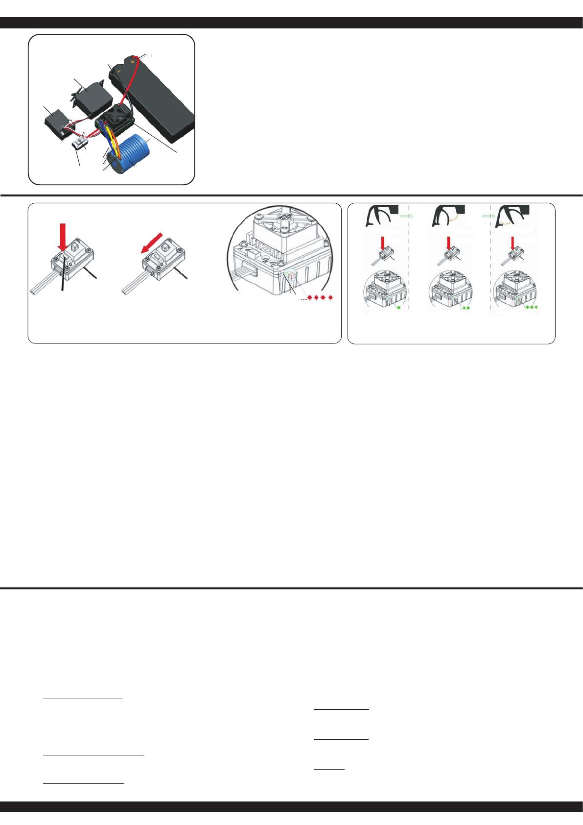
Collegamento della ricevente, la batteria e il motore
Collegare il regolatore, la ricevente, la batteria, il servo e il moto-
re in base alla seguente tabella. Prestare attenzione alla polarità
della batteria di alimentazione. Collegare il lo rosso al terminale
’+’ e il nero con il ’-’ della batteria. I terminali ’#A’, ’#B’ e ’#C’ de-
vono essere collegati ai morsetti del motore. Il tasto ’SET’ viene
usato per la programmazione. Collegare l‘uscita del „canale 2“
della ricevente con il regolatore. Osservate l‘assegnazione dei
canali sul telecomando. Collegare le uscite del regolatore ai mor-
setti del motore. Non esiste un´assegnazione consigliata. Dopo
che tutto è collegato, è ne cessario di eseguire un test. Se il mo-
tore gira nella direzione sbagliata e consigliato di invertire i cavi
oppure vericare il tasto reverse sul radiocomando.
Nota
È possibile utilizzare la funzione inversa del radiocomando per
cambiare la direzione di rotazione del motore. È necessario di
riprogrammare il regolatore.
GB - Using Your ESC
Connecting the Receiver, Battery Pack and Motor
Connect the ESC, motor, receiver, battery and servo according
to the diagram.
Ensure that you observe the correct polarity of the battery pack.
The red cable should be connected to the ‘+‘ Plus Pole and the
black cable to the ‘-‘ Minus Pole. The ’#A’, ’#B’ and ’#C’ plugs
are connected to the motor. The ‘SET‘ button initiate the pro-
gramming mode.
The ESC should be plugged into the throttle channel of your re-
ceiver which is normally channel 2. If in doubt, check your Radio-
Control System’s instructions. The 3 Motor wires (#A’, ’#B’ und
’#C’) can now be connected, these connectors can be plugged in
any order, and if the motor rotates in the wrong direction any 2 of
the wires should be swapped.
Note:
You can use the servo reverse function of your transmitter to
reverse the motor direction but the ESC will have to be re-ca-
librated afterwards.
Motor
#C
ESC
channel 2
Switch
Receiver
Channel 1
Servo
Plus pole
red cable
Minus pole
black cable
Set
ON/OFF
Apprendimento della corsa gas / freno
Per prestazioni ottimali, il regolatore deve essere calibrato. In tal modo, le tre posizioni avanti,
indietro e la posizione di folle devono essere specicata. Ci sono tre ragioni per la necessità di
calibrazione:
• Durante il primo avvio
• Eettuando un cambio della trasmittente
• Dopo una riprogrammazione del punto neutro e / o la corsa del servo del trasmettitore
Durante la regolazione procedere come segue:
1. Accendete il radiocomando, durante che la ricevente è spento. (Attenzione con sistema di
Futaba: In certi casi la funzione del gas è invertita). La corsa servo deve essere in posizione
neutrale. Fare attenzione che la funziona ABS sia spenta.
2. Poi accendere la ricevente tramite l‘interruttore sul regolatore. Tenendo premuto il tasto ‚SET‘.
Questo vi porterà alla modalità di calibrazione, il LED inizia a lampeggiare. Appena il LED
lampeggia, rilasciare il pulsante. Se non si rilascia il tasto ‚SET‘ subito dopo il LED inizia a
lampeggiare e si entra nella modalità di programmazione. Se non si desidera questo, è
necessario a spegnere nuovamente il regolatore. La gura seguente mostra il processo
d’inizio di calibratura.
3. E´possibile congurare tre parametri:
• Posizione neutra
• Fine corsa marcia avanti
• Fine corsa marcia indietro
In seguito trovate le immagini,dove sono presentati i processi e le procedure gracamente.
4. Portare la leva del gas in posizione neutrale e premere il tasto ‚SET‘, il LED verde lampeggia
una volta e il motore emette un suono. Portare la leva del gas in posizione nale per il
movimento in avanti e premere il tasto `SET il LED verde lampeggia due volte e il motore
emette due suoni. Portare la leva del gas in posizione nale per il movimento indietro e
premere il tasto `SET`, il LED verde lampeggia tre volte e il motore emette tre suoni. Attendere
tre secondi, dopodiché è terminato il processo di calibrazione.
Throttle range calibration
To ensure that your ESC operates correctly it has to be calibrated. During this process the full
throttle, stop and brake positions will be set. There are 3 occasions when the unit must be
calibrated.
• Before using the ESC for the rst time
• If you change to a new transmitter
• If the neutral point or servo throw is changed within your transmitter
To calibrate the system, please proceed as follows:
1. Ensure that the receiver is switched OFF and switch ON the transmitter. If you are using a
Futaba transmitter. The throw should be set to neutral. If the transmitter is tted with an ABS
function this must be de-activated.
2. Press and hold down the ‘SET‘ button on the ESC and switch the receiver switch ON. This will
switch the ESC into Calibration’ mode and the LED will begin to blink. If you fail to release the
‘SET’ button as soon as the LED blinks, the ESC will enter ‘Programming’ mode. If this
happens, you will have to switch the ESC o and start again to enter ‘Calibration’ mode.
3. Parameters can be set here:
• Neutral point
• Full throttle forwards
• Full throttle reverse
The procedure for setting these 3 points is outlined below:
4. Ensure that the throttle control is in the neutral position and press the ‘Set‘ button. The green
LED will ash once and the motor will omit a beep. Move the throttle control to the full throttle
(forwards) position and press the green ‘Set‘ button. The green LED will ash twice and the
motor will omit 2 bleeps. Move the throttle control to the full reverse position and press the
‘Set‘ button. The green LED will ash 3 times and the motor will omit 3 bleeps. 3 Seconds after
this procedure has been followed, the motor is ready for use.
Gusto presa sul SET Stampato interruttore ON Lasciate che il pulsante SET quando
le luci rosse lampeggiano crostate
Hold the SET keep button Turn on the switch Release the SET button as soon
as the red LEDstarts to blink
Segnali e dispositivi di sicurezza
Durante il normale funzionamento, i segnali LED hanno i seguenti signicati:
a. Quando l‘acceleratore è in posizione neutra, non è accesa né la LED rossa né la LED verde.
b. Il LED rosso si accende quando il veicolo è in movimento in avanti o indietro. Durante la
frenata, il LED rosso lampeggia velocemente.
c. I LED verde si accende quando il generatore di gas e in max. posizione avanti o indietro.
Tramite segnali d’avviso, il regolatore richiama l‘attenzione su determinate condizioni:
1. Durante l´avvio, il processore controlla la tensione d’ingresso, quando è al di fuori dei limiti
consentiti, un tono duale con una pausa di un secondo tra i singoli segnali „bipbip, bip-bip,
bip-bip-“ lo segnala.
2. Quando il segnale d’ingresso non è corretto, sarà generato un suono con una pausa di due
secondi tra i singoli segnali „bip-,-bip, bip-“. Questo regolatore è dotato di una serie di
dispositivi di sicurezza per un funzionamento sicuro:
1. Spegnimento sottotensione:
Non appena la tensione di una batteria LiPo, per un periodo di 2 secondi, va sotto la soglia
impostata, il motore si spegne. Notate che il motore non può essere riavviato, se la tensione
di una cella è inferiore a 3,5 V. Batterie NiCd o NiMH con una tensione compresa tra 9,0 V e
12,0 V, sono trattate come una batteria LiPo a tre celle. Le batterie con meno di 9.0 V come
un due-celle LiPo-Pack. Se per esempio, una batteria NiMH ha una tensione di 8,0 V, e la
soglia è impostata a 2,6 V per cella LiPo, l‘arresto avviene a 5,2 V (2 x 2,6 V). Cosi anche le
celle di NiCd, sono ecacemente protetti contro una scarica profonda.
2. Spegnimento per sovratemperatura:
Appena la temperatura del regolatore, per una durata di 5 secondi, supera il valore di 95 ° C,
il motore si spegne. Dopo lo spegnimento, è necessario lasciare rareddare il regolatore,
altrimenti il regolatore sarà danneggiato. Questa funzione non può essere disabilitata!
3. Segnale d´ingresso difettoso
Se il segnale d’ingresso per un periodo di 0,2 sec è rilevato come errato e motore si spegne.
LED’s, errors and protection
In normal use the LED will illuminate as follows:
a. If the throttle control is in the neutral position, neither the red or green LED will illuminate.
b. The red LED will illuminate if the vehicle is driving forwards or in reverse. If the vehicle is
braking, the red LED will ash rapidly. When the car moves forward, the red LED solidly
lights; the green LED also lights up when the throttle stick is at the top position (100%
throttle).
c. The green LED will illuminate when the vehicle is at full throttle either forwards or in reverse.
In certain circumstances the ESC will omit an acoustic tone to warn you of a problem:
1. On switching on, the ESC will check the battery pack voltage and if it falls outside the correct
values it will omit double signals followed by a 1 second pause: “beep-beep-, beep-beep-,
beep-beep-”
2. If the ESC does not receive a signal from the transmitter it will omit single signal followed by
a 2 second pause: “beep-, beep-, beep-”
The ESC has ben equipped with a series of protective circuits to ensure safe operation:
1. Low voltage cut-o:
If the voltage drops below the set value for more than 2 seconds the ESC will switch the
motor o. Please note that the motor cannot be started again if the voltage is below the
choosen value per cell.
2. Temperature cut-o
If the internal temperature of the ESC rises above 95°C for more than 5 seconds the motor
will switch o. After the ESC switches o it has to cool down before operating again.
Otherwise the ESC will be damaged. This function should not be disabled!
3. Signal loss
If the signal is lost for more than 0.2 seconds the ESC will switch the motor o.
LED verde
lampeggia una volta
Green LED ashes
once
LED verde
lampeggia due volte
Green LED
ashes twice
LED verde
lampeggia tre volte
Green LED
ashes thrice
8
Le caselle grigie indicano l‘impostazione consigliata. The elds which are shaded in grey indicate the factory recommended setting.
Programmazione del regolatore Programming the ESC
Fase di programmazione
Program Mode
Valori del programma
Program Value
1 2 3 4 5 6 7 8
1. Modalità di guida
Drive Mode
In avanti freno on
Forwards, brake on
avanti / indietro,
freno on
forwards / reverse,
brake on
2. Freno
Drag Brake Force
0 % 5 % 10 % 15 % 20 % 25 % 30 % 40 %
3. Sottotensione
Low Voltage OFF 2,6 V/celle
2,6 V/cell
2,8 V/celle
2,8 V/cell
3,0 V/celle
3,0 V/cell
3,2 V/celle
3,2 V/cell
3,4 V/celle
3,4 V/cell
4. Start Modo
Start Mode
sanft
soft
normal
normal
aggressivo
aggressive
molto aggressivo
very aggressive
5. Forza frenante massima
Brake Max.
25% 50% 75% 100%
Nota importante:
Oltre ai segnali lampeggianti del LED rosso, sono generati anche segnali acustici dal motore. Al
termine di ogniprogrammazione, il regolatore deve essere prima spento. Dopo il riavvio, la nuova
congurazione avrà eetto.
Important note:
In addition to the red LED blinking, the motor will omit an acoustic signal. After every change to
the values the ESC must be switched o to store the values. The new settings will not be eective
until the ESC is re-started.
Struttura del menu del regolatore Menu structure
Accendere il regolatore, mentre si
preme il tasto ‚SET‘.
Press and hold the ‘SET‘ button
down and switch the receiver on
Il LED rosso lampeggia
The red LED blinks
Accendere il regulatore
Accendere il trasmettitore
Turn o the ESC
Switch transmitter ON
Die grüne LED blinkt einmal
The green LED blinks once
Il LED verde lampeggia 2 x
The green LED blinks twice
Il LED verde lampeggia 3 x
The green LED blinks 3 times
Il LED verde lampeggia X x
The green LED blinks X times
Premere il
pulsante
per 3 secondi
Press the button
for 3 seconds
Lasciare il tasto
Release button
Lasciare il tasto
Release button
Lasciare il tasto
Release button
Lasciare il tasto
Release button
Premere il tasto
Press button
Fase di programmazione 1,
modalità di guida
Program option 1, Drive mode
Fase di programmazione 2,
modalità die frenata
Program option 2, Brake mode
Fase di programmazione 3,
sottotensione
Program option 3, Low voltage cut-o
Fase de programmation X
Program Option
Il LED rosso lampeggia una volta, cioè, signi ca andare avanti con freno
Red LED blinks once indicating forwards and brake.
Il LED rosso lampeggia due volte indicando marcia avanti, retromarcia e freno.
The red LED blinks twice indicating forwards, reverse and brake.
rosso | red LED lampeggia | blinks 1 x ► 0 %
rosso | red LED lampeggia | blinks 2 x ► 5 %
rosso | red LED lampeggia | blinks 3 x ► 10 %
rosso | red LED lampeggia | blinks 4 x ► 15 %
rosso | red LED lampeggia | blinks 5 x ► 20 %
rosso | red LED lampeggia | blinks 6 x ► 25 %
rosso | red LED lampeggia | blinks 7 x ► 30 %
rosso | red LED lampeggia | blinks 8 x ► 40 %
rosso | red LED lampeggia | blinks 1 x ► OFF
rosso | red LED lampeggia | blinks 2 x ► 2,6 V
rosso | red LED lampeggia | blinks 3 x ► 2,8 V
rosso | red LED lampeggia | blinks 4 x ► 3 V
rosso | red LED lampeggia | blinks 5 x ► 3,2 V
rosso | red LED lampeggia | blinks 6 x ► 3,4 V
Si prega di premere il tasto ‚SET‘ per ogni modi ca del valore corrente, il LED
rosso indica ciascuno dei valori, lampeggiare una volta signi ca che è imposta-
to su valore 1, due volte sul valore 2 ecc.
Press the ‘SET‘ button to select the desired value. The red LED will indicate
which value is selected. 1 X blink indicates value 1, 2 x blinks indicate value
2 etc.
Tutte le fasi seguenti di programmazione si svolgano nella stessa maniera
All of the other menu options are accessed in the same manner.
Premere il
pulsante
per 3 secondi
Press the button
for 3 seconds
Premere il
pulsante
per 3 secondi
Press the button
for 3 seconds
Premere il tasto
Press button
Premere il tasto
Press button
Premere il tasto
Press button
9
Questo regolatore è dotato di numerose opzioni di congurazione. Per raggiungere il Suo obiettivo
di programmazione ottimale in modo rapido e sicuro, si tiene fede al menu mostrato nella struttura
della tabella sopra e le opzioni di programmazione. Le singole fasi di programmazione della tabella
hanno i seguenti signicati:
1. Modalita´di guida
Nel modo gara punto 1, il veicolo sta viaggiando solo in avanti, il freno e´attivato, la marcia
inversa e´escluso. Questa modalità è adatta per le competizioni. In modalità di guida, punto
2 (avanti / indietro con freno), il veicolo può anche invertire con funzione freno attivato.
Questa modalità è adatta per le operazioni normali e per principianti.
Nota:
Nella 2.modalità di guida, è necessario confermare l´operazione due volte per avere l´eetto
d’inversione. Se si passa la leva in avanti, per la prima volta nella zona inversa, il motore
frena. Il veicolo si ferma, ma non totalmente. Ora, se la leva viene premuto nuovamente nella
zona inversa, inverte il veicolo, pero prima si ferma brevemente. Quando la leva viene
nuovamente spostato in avanti, indipendente se il motore è in frenata o in modalità inversa, la
macchina poi viaggia nuovamente in avanti.
2. Freno:
In questo menu, l‘azione minimo di frenatura del freno, viene impostato come valore. Il campo
di regolazione è compreso tra 0 e 40%.
3. Sottotensione
In questo punto po’ essere impostato il valore di spegnimento. L‘intervallo d’impostazione è
tra 3,4 - 2,6 V per cella. Appena è superata la soglia, il regolatore spegne il motore.
4. Start Modo:
Con questa opzione è possibile impostare come deve essere eseguito la partenza. C’è la
possibilità di scegliere tra 4 modi, diversi, da delicato a molto aggressivo. Si noti che per le
modalità „aggressivo e molto aggressivo“ si deve usare batterie particolarmente potenti con
bassa resistenza interna. In caso contrario, avvengono sottotensione e il motore gira su solo
con ritardo. Inoltre, il motore e la trasmissione sono da regolare, secondo la modalità di
avviamento desiderata.
5. Forza frenante massima:
Il regolatore è dotato di un freno che agisce proporzionale alla posizione della datrice. Il più
forte eetto si ottiene quando la leva viene spinto completamente in avanti. Un forte eetto
frenante porta il veicolo a un arresto rapido, che d‘altra parte, è collegato a un elevato grado
di usura dei parti meccanici come per esempio l´ingranaggio.
Per aggirare la programmazione tramite il pulsante Setup, il regolatore può anche essere
programmato facilmente tramite la scheda di programmazione venduto separatamente
(Art.Nr. 081454).
This ESC is tted with many useful functions and to help you to be able to make the most of the
various options they are explained below. Please use the programming table shown on page 6
together with these explanations to program your ESC quickly and eectively:
1. Drive mode:
If option 1 is selected in Drive mode, the vehicle will only drive forwards and the brake is
active which make this mode the best choice for racing. In mode 2 the vehicle can be driven
forwards or in reverse and the brake is also active. This mode is useful for general use and
training.
Note:
When option 2 is selected, moving the throttle control back past the neutral point will initially
activate the brake. If the throttle control is then moved back to the neutral position briey the
ESC will switch over to reverse. Moving the ESC forwards will make the vehicle drive
forwards regardless of whether it was braking or moving in reverse.
2. Drag Brake force:
In this option the drag braking force can be set. The value is set as a percentage and the
values are from 0 to 40%
3. Low voltage:
In this option you can set the low voltage cut-o value. The cut-o voltage can be set between
3.4 and 2.6 Volts per cell. Once the cut-o voltage has been reached the motor will stop.
4. Start Mode:
With this option you can choose how the vehicle will accele rate when full throttle is applied
and you can set the value between ‘Soft‘ and ‘Very Aggressive‘. Please note that if you select
one of the 2 ‘Aggressive’ modes that you will need to have batteries with a very low internal
resistance otherwise the voltage will drop due to the high current draw and the motor may
stutter. Also ensure that your motor and gearing are capable of carrying the high loads.
5. Brake Max.:
The ESC is equipped with a braking system which works proportionally to the throttle control.
This means that the further the throttle control is moved rearwards the more braking force will
be applied. A higher value here will mean that the vehicle will brake harder but more strain will
be placed on the components, for example, the gearing.
To avoid the programming procedere with the set up botton, you can all so use the seperatly
available Programmcard (Ord.No. 081454).
Collegamento di una scheda di programmazione
Per collegare la scheda di programmazione al regolatore di velocità, scollegare il cavo del ventilatore
(1) dal collegamento tra i cavi del motore. Collegare il cavo della scheda di programmazione, accer-
tandosi che il cavo sia collegato correttamente (vedi schema di collegamento Fig. 2). Assicuratevi di
ricollegare il cavo della ventola dopo aver terminato la programmazione.
Connecting the programming card
To connect the programming card to the speed controller, disconnect the fan cable (1) from the
connector between the motor cables. Connect the cable to the programming
card, making sure that the cable is connected correctly (see connection diagram, Fig. 2). Be sure to
reinsert the fan cable after completing the programming.
Cavo per ventilatore
Fan cable
Schema di collegamento
Connect memory card
10
505073
505074
505076
505024
505024
505023
505145 Vers. BL
505166 Vers. EP
505078
505075
505071
505073
079989
079996
070806
505134
505156
505275
505156
505138
505073
505078
505075
505072
505071 505076
505071
505074
079989
505081 505079
079989
505028
505042
505040
079989
505084
505276 505041
505061 505079
505080
07 9996
Montaggio dierenziale anteriore
Front gear assembly diagram
Montaggio dierenziale anteriore
Rear gear assembly diagram
Montaggio sterzo e braccetti inferiori
Steering assembly diagram
11
505082
505090
505082
505061
079989
079996
505084
505044
505040
505057
505054
505057
505028
505043
505054
505133
Montaggio assetto posteriore
Rear shaft assembly diagram
Montaggio ammortizzatori
Shock assembly
Montaggio ammortizzatori
Shock assembly
12
505077
505026
505036
505029
505101
505030
505037
Montaggio Servo Saver
Buer assembly
Montaggio Motore e Pignone
Motor assembly
Montaggio anteriore e posteriore
Front & rear assembly
505126 Pignone BL
Motor gear BL
505167 Pignone EP
Motor gear EP
13
505165
505341
506119
505148
505093
505279
505286
Montaggio piastra radio
Top plate assembly
Montaggio roll cage
Cage assembly
14
4
505116
nero | black
505280
rosso | red
Montaggio anteriore e posteriore
Front & rear assembly
IT - Appena acceso il veicolo, si attivano anche i LED sono attivi.
GB - If you activate the model now, the LED´s are activ.
IT - In stato di consegna, i LED non sono attivi.
GB - The LED´s are not connected on delivery under certain
circumstances.
IT - Il connettore per il LED si trova nella scatola della radio
GB - The LED connector is stored in the receiver box.
IT - Inserire la spina del LED nel ricevitore sul canale 3 (CH3).
Inserire il cavo nero (meno) sulla destra esteriore.
GB - Put the LED connector into the receiver to channel 3 (CH3).
The black line (minus) belongs to the right side.
IT - Aprire la scatola ed estrarre la spina dei LED ed il ricevitore..
GB - Open the receiver box and take out the LED connector
and the receiver.
IT - Installare il ricevitore e cavi attentamente nella scatola.
Assicurarsi che i cavi corrono attraverso la guida esterna.
Non fratturare i cavi.
GB - Put the receiver and the wiring back to the receiver box and
take care to install the wiring proberly. Dont squeeze the
wiring.
IT - Chiudere la scatola del ricevitore.
GB - Close again the receiver box with the two pins.
Spina LED
LED-connector
Ricevitore canale 3
receiver-CH3
15
Screw
Screw = less spring travel
Unscrew = more spring travel
Clip
front mounted =
higher caster
rear mounted =
lower caster
Spring tension
(less or more clip)
Shock angle
Toe, front Caster
Spring tension
(less or more clip)
Shock angle
rear / top
Rear camber
IT - Punti impostazione GB - Setting points
IT - Impostazione dell’assetto / sospensione
A Convergenza negativa:
Sterzo e meno diretto e la macchina tende a
sovrasterzare. Guida diritta più precisa.
B Convergenza positiva:
Sterzo e più diretto e la macchina tende a
sottosterzare. Guida diritta meno precisa.
Ruotare l‘asta del tenditore più corta =
convergenz negativa
Ruotare l‘asta del tenditore più a lungo =
convergenz positiva
GB - toe-in / toe-out
A Toe-in: The responsiveness of the steering is
less direct and the vehicle tends to
oversteer, but it has better directional
stability.
B Toe-out: More direct steering response and
understeer, but has a worse directional
stability.
Turn the Turnbuckle shorter = Toe-out
Turn the Turnbuckle more = Toe-in
IT - Inclinazione alto/basso anteriore
Basso: Inclinazione bassa ha una guida dritta
peggiore, ma un sterzo più preciso e una
migliore entrata in curva.
Alto: Inclinazione alta ha una guida dritta
migliore, ma un sterzo meno preciso e
l’entrata in curva peggiore.
GB - Front caster high / low
Less caster: Less caster has a worse directional
stability, but provides a better steering on
corner entries.
High caster: A higher caster has a better directional
stability, but can result in worse corner
turn-in.
Suspensione molla
(basso o meno clip)
Suspensione molla
(basso o meno clip)
Angolo sospensione
posteriore / sopra Angolo sospensione
Inclinazione posteriore Inclinazione anteriore Inclinazione
Tenditore
girare più breve = Toe-out
girare più = Convergenz
Angolo di inclinazione
Caster angle Clip
montato anteriore =
Inclinazone alto
montato posteriore =
Inclinazione basso
16
Rear camber
A
A
BB
Clip
teso
rm
morbido
soft
Angolo sospensione
Shock angle
Inclinazione
posteriore
IT - Campanatura - Positivo / Negativo anteriore
e posteriore
È possibile regolare la campanatura anteriore ruotan-
do una delle viti interne della sospensione anteriore pi-
votante. Ruotare entrambe le viti uniformemente verso
l’interno o verso l’esterno per regolare la carreggiata.
Per regolare la campanatura posteriore, ruotare l’asta
della guida posteriore.
A Negativo:
Migliore aderenza nel terreno. Poiché i bordi delle
ruote si sollevano nel sottosuolo mentre la
macchina entra in curva. Questo permette una
velocità più elevata nelle curve. Consigliamo ca.
1,5 gradi negativo anteriore e 0 grado posteriore.
Inclinazione eccessiva causa un peggioramento
della qualità guida.
B Positivo:
Inclinazione positivo è da evitare, dato che questo
causa un guida non precisa.
GB - Negative / positive camber front and rear
You can adjust the front camber by turning one of the
inner screws on the pivot front suspension. Turn both
screws equally inwards or outwards to adjust the track
width.
To adjust the rear camber, turn the rear track rod.
A Negative camber:
Better grip on terrain, as the edge of the wheels
stem into the ground allowing higher cornering
speed. We recommend approx. imately 1.5
degrees negative front and an ave rage of 0
degree to the rear. An excessive negative camber
angle can deteriorate the ride quality.
B Positive camber:
A Positive camber should be avoided in your
vehicle due to poorer ride quality.
Inclinazione
(Solo vite interna)
Front camber
(only inner screw)
IT - Precarico molla anteriore e posteriore duro/morbido
Per regolare il precarico della molla, tirare leggermente verso il basso la molla e
inserire la clip desiderata.
Duro: Risposta diretta del telaio, ma la presa ridotta.
Morbido: Meno risposta diretta del telaio, ma più presa
GB - Spring tension hard / soft front and rear
To adjust the spring preload, pull the spring down a little and insert the desired clip´s.
Harder: More direct response of the suspension but reduced grip.
Softer: Less direct response of the chassis but more grip.
Precarico molla
Spring tension
duro
Harder
IT - Angolo sospensione morbido/teso anteriore e posteriore
Per regolare l‘angolo della serranda, rimuovere la vite sul braccio di
sospensione, regolare l‘angolo e serrarlo di nuovo
Morbido = Sterzo diretto
Teso = Sterzo meno diretto
GB - Damper angle soft / rm front and rear
To adjust the damper angle, remove the screw on the suspension arm, adjust the
angle and tighten it again.
Soft = More direct steering
Firming = Less direct steering
Morbido
Softer
17
Pezzi di ricambio Spare parts
No. 505145 BL
Corona principale
Mid-dierential gear set
No. 505166 EP
Corona principale
Mid-dierential gear set
No. 505024
Albero
Rear main gear set
No. 505026
Soporto motore
Motor mount set
No. 505165
Piastra radio
Radio plate
No. 505093
Coperchio corona
Cover for main gear
No. 505028
Perno braccetti
Suspension arm shaft set
No. 505167 EP
Pinone motore | Pinion
No. 505126 BL
Pinone motore | Pinion
Version EP
No. 505025
Motore elc. c. albero 3,17mm
E-Motor with 3,17mm shaft
Version EP
No. 081449
Reguladore
Speed Controller
Version BL
No. 081460
Motore elc. c. albero 3,17mm
E-Motor with 3,17mm shaft
Version BL
No. 081448
CR B60WP 60A Brushless
Reguladore
Speed Controller
No. 505030
Cardanol
Central shaft set
No. 505101
Chassis
Chassis
No. 505032
Soporto batteria
Battery case
No. 505029
Servo Saver Set
Steering saver set
No. 505341
Perno sterzo
Servo pulling rod set
No. 505036
Sterzo
Steering connecting set
No. 505037
Paraurte
Bumper plate set
No. 505156
Uniball
Upper ball head
No. 505076
Bicchierino centro
Connecting cup
No. 505040
Supporto braccettoSuspensi-
on xed mount set
No. 505041
Braccetto anteriore/superiore
Front upper suspension set
No. 505042
Braccetto inferiore/superiore
Front lower suspension set
No. 505043
Braccetto inferiore/posteriore
Rear lower suspension set
No. 505044
Braccetto post./sup.
Rear upper connecting
rod set
No. 505133
Ammortizzatore
Shocks
No. 505276
Albero motore davanti
Swing shaft front
No. 505134
Spoiler
Spoiler
No. 505136
Supporto Spoiler
Spoiler support
No. 505116 1:10
nero | black
Ruota + Cerchi
Tires + Rims
No. 505280 1:10
rosso | red
Ruota + Cerchi
Tires + Rims
No. 505138
Supporto Ammortizzatore
Damper support front + rear
No. 505085
Perno A di.
Bevel gear A di.
No. 505071
Perno B di.
Dierential bevel gear set
No. 505072
Perno + Albero
Dierential bevel gear set
No. 505073
Corona di
Bevel gear
No. 505074
Cassa di.
Dierential case set
No. 505075
Cassa esterna di.
Gear box set
No. 505077
Servo Saver supp. c. E-clip
Buer steel column set
No. 505078
Supporto di. ant./post.
Shock mount set
No. 505079
Fusello davanti
Steering hub set
No. 505080
Cuscinetto
Ball head nut set
No. 505081
Pivot-Viti a testa sferica
Ball head screw set
No. 505082
Forcella st
Rear shaft hub set
No. 505054
Perno praccetto
Suspension arm shaft set
No. 505084
Trascinatore
Hexagonal joint set
No. 505131
Bracetti-Perno
Joint set
18
Pezzi di ricambio Spare parts
Pezzi Tuning e accessori Tuning parts and accessories
No. 505277
Albero motore posteriore
Driveshaft rear
No. 505045 Ø 7
E-clip
E-clip
No. 505046 Ø 4
E-clip
E-clip
No. 505047 Ø 2,5
E-clip
E-clip
No. 079989 Ø10*Ø15*4
Cuscinetto
Ball bearing
079996 Ø5*Ø11*4
Cuscinetto
Ball bearing
No. 070806 Ø5*Ø10*4
Cuscinetto
Ball bearing
No. 059078 M3*8
Viti testa svasata
Countersunk head screw
No. 506145 M3*10
Viti testa svasata
Countersunk head screw
No. 505053 M3*6
Viti testa svasata
Countersunk head screw
No. 505055 3*10
Vita testa svasata
Flat head self tapping cross
screw
No. 505057 M3*10
Vite
Umbrella head machine cross
screw
No. 505060 M3*3
Vite
Set screw
No. 505058 M3*8
Vite
Umbrella head machine cross
screw
No. 505059 M3*10
Vite
Set screw
No. 505061 2*11
Pin
Pin
No. 505062 2*10
Pin
Pin
No. 505063 Ø4*Ø8*0.5
Guarnizione
Shim
No. 059273
Graette per carrozzeria
Body-Clip
No. 059274
Graette per carrozzeria
Body-Clip colored
No. 177444 M4
Dati autobloccanti
Lock nut
No. 059116
Copertura ingranaggio
Gearbox cover
No. 505023
Trascinatore corona
Gear mount set
No. 505279
Roll cage
Roll cage
No. 505285
Box ricevente
Receiver box
No. 505155
Di. davanti-dietro.
Di set front+rear
No. 505253
O-Anello
O-Rings
No. 505283
Foglio decorativo
Decal sheet
No. 140141 NiMh
7,2 V 2000 mAh
Batteria
Battery
No. 505271
NiMh-Caricatore
NiMh-Charger
No. 141390 LiPo-Racing
7,4V 5000mAh 2N 30C
Batteria presa a T
Battery T-socket
No. 141391 LiPo-Racing
7,4V 5000mAh 2N 30C
Batería spina di Tamya
Battery Tamya plug
No. 413117 LiPo 20 2/3S
Caricadore
Charger
No. 505270
Caricatore Tam
Charger Tam. Connection
No. 506119
Servo
Servo
No. 506154
Trasmittente
Transmitter
No. 505162
Cardano davanti
Cardan front
No. 505086
Alu ammortizzatori
Alu shock absorber
No. 503581
Dado, autobloccante
Nut with border, self-lockin
No. 505548
solo per Brushless!
Corona princ. 65D
only for brushless!
Main gear 65T
No. 033215
Q7 Standard
Servo
Servo
No. 033216
High End MG 13/18
Servo
Servo
No. 061171
CCX/SCX 2,4GHz
Ricevente
Receiver
No. 505281
Carrozzeria
Body
No. 505282
Carrozzeria, chiara
Body clear
19
Soluzione dei problemi
Dopo l‘accensione il motore non parte e non rilascia alcun segnale acustico.
1. La batteria o il collegamento alla batteria non sono in ordine.
- Controllare i cavi, connettori e batteria.
Dopo l‘accensione, il motore non si avvia, viene emesso un segnale in un ciclo di 1 sec.
1. La tensione di ingresso non è corretta, è troppo alta o troppo bassa.
- Controllare il livello di tensione della batteria.
Dopo l‘accensione, il motore non si avvia, viene emesso un segnale in un ciclo di 2 sec.
1. Il segnale di ingresso viene riconosciuto come non corretto.
- Controllare la trasmittente e il ricevitore, nonché il cavo di collegamento del ricevitore del
regolatore.
Il motore gira in una direzione errata.
1. I collegamenti del motore in senso inverso.
- Sostituire due cavi di collegamento tra il motore e il regolatore.
Improvvisamente il motore non gira più
1. Il segnale d´ingresso non è corretto.
- Controllare trasmettitore, ricevitore e il cavo servo.
2. La batteria ha una tensione troppo bassa.
- Caricare la batteria.
Funzionamento irregolare del motore, balbetta.
1. Vi è una connessione allentata.
- Controllare tutti i collegamenti in grande dettaglio.
2. La trasmissione radio subisce forti interferenze intermittenti.
- Ruotare il controllo spento e riacceso. Se an cora non si ottiene un corretto funzionamento,
utilizzare il vostro veicolo in qualsiasi altro lu ogo.
Modello non risponde
1. Batterie scariche o difettose
- Caricare, sostituire le batterie
2. Motore difettoso
- Sostituire il motore
3. Cavi allentato o danneggiato
- Ricollegare o sostituire i cavi
4. Trasmettente spenta, danneggiato o perso il binding
- Accendere la trasmittente o rieettuare il binding
5. Ricevente diettoso
- Sostituire la ricevente
6. Regolatore di velocità difettoso oppure non correttamente collegato
- Sostituire oppure ricollegare il regolatore
Modello reagisce in maniera incontrollata
1. Trasmettente spenta, danneggiato o perso il binding
- Accendere la trasmittente o rieettuare il binding
2. Regolatore programmato non correttamente
- Riprogrammare il regolatore
3. Ricevente diettosa
- Sostituire la ricevente
Motore reagisce in modo strano appena acceso la trasmittente
1. Fail Safe male impostato
- Riprogrammare il Fail Safe
2. Trim del Gas non in posizione neutrale
- Trimmare il Gas
Modello va solo in avanti
1. Regolatore programmato non correttamente
- Riprogrammare il regolatore
Reagisce solo il sterzo ai comandi
1. Regolatore oppure motore diettoso
- Sostituire il regolatore oppure motore
Sterzo non risponde
1. Servo sterzo diettoso
- Sostituire il servo sterzo
2. Dualrate non impostato correttamente
- Impostare Dualrate
3. Leva del sterzo sporco
- Pulire la leva del sterzo
Forte rumore dalla trasmissione
1. Ingranaggio principale, pignone o dierenziale danneggiati
- Non continuare la guida! Sostituire la parte difettosa
2. Distanza pignone corona non impostata bene
- Controllare il giocho tra pignone - corona
Regolatore di velocità si spegne durante la guida
1. Blocco della sottotensione, tensione batteria bassa
- Caricare la batteria
2. Spegnimento per temperatura eccessiva
- Fare rareddare il regolatore di velocità
Perdita dei cardani anteriore
1. Larghezza carreggiata elevata
- Riduree la distanza
Troubleshooting
The motor will not rotate after switching on. No signal is present.
1. The battery pack or battery pack connectors are faulty.
- Check all of the connectors and the battery pack.
After switching on, the motor does not start, a signal is emitted at 1 sec. intervals.
1. The input voltage is too high or too low.
- Check the battery pack voltage.
The motor will not turn after switching on, a signal is emitted at 2 second intervals.
1. No or a poor receiver signal.
- Check both the transmitter and receiver as well as the ESC connecting cable.
The motor turns in the wrong direction.
1. The motor connecting cables are swapped
- Swap 2 of the ESC/motor connecting cables
The motor suddenly stops turning.
1. The battery voltage is too low.
- Charge the battery pack.
2. No signal.
- Check the transmitter, receiver and all of the cables only steering response
The motor stutters or runs irregularly.
1. One of the connectors is loose.
- Carefully check all of the connectors.
2. The receiver has intermediate interference.
- Switch the system o and then on. If the interference persists, operate the model in another
location.
Model does not respond
1. Battery or batteries empty or defective
- Charge battery or replace
2. Motor broken
- Replace motor
3. Loose or damaged cable
- Reconnect cable or replace
4. Transmitter turned o, lost or damaged binding
- Transmitter back on, bind or replace
5. Defective receiver
- Replace receiver
6. Speed controller is defective or connection issue
- Connect properly or replace
Model react uncontrolled
1. Transmitter turned o, lost or damaged binding
- Transmitter back on, bind or replace
2. Controller not calibrated or programmed incorrectly
- Recalibrate or reprogram
3. Defective receiver
- Replace receiver
Engine is running when you turn on inadvertently
1. Incorrectly set Failsafe
- Failsafe program to neutral
2. Throttle trim on the transmitter is not in neutral
- Throttle trim set to neutral
Model moves forward only
1. Controller not calibrated or programmed in correctly
- Recalibrate or reprogram
Only steering response
1. Regulator or Motor is defective or not Calibrated
- Calibrate speed controller or replace motor
Steering does not respond
1. Power steering defect
- Replace servo
2. Dual Rate on the transmitter set too low or to 0
- Dual rate increase
3. Very dirty steering lever or steering knuckle
- Clean and lubrcate well
Loud noise from the drive
1. Main gear, pinion or dierential damage
- Do not continue! aected part needs to be replaced
2. Incorrect gear mesh
- Reset gear mesh
Speed controller shuts o while driving
1. Low voltage cut-o, battery voltage too low
- Charging the battery
2. Overtemperature
- Let speed controller cool
Front drive shafts fall out
1. Too large track width
- Track width reduction
Pezzi Tuning e accessori Tuning parts and accessories
No. 130156
Raredamento motore Allu
attivo con ltro
Cooling ns active with fan
No. 130157
Raredamento motore Allu
attivo vario con ltro
Cooling ns alu active
variable with fan
No. 505182
Wheelybar
Wheelybar
No. 506088
Wheelybar Dual Wheel
No. 061222
Compa X3 Evo 2,4 GHz
Trasmittente
Transmitter
No. 061201
CCX LiPo 2,4 GHz
Trasmittente
Transmitter
No. 061200
CCX Pro 2,4 GHz
Trasmittente
Transmitter
No. 081454
Carta programmazione
Programming card
No. 505284 Ø 19 mm
Proiettore LED
Spotlight
JAMARA e.K.
Inh. Manuel Natterer
Am Lauerbühl 5 - DE-88317 Aichstetten
Tel. +49 (0) 75 65/94 12-0 - Fax +49 (0) 75 65/94 12-23
[email protected] www.jamara.com
Service - Tel. +49 (0) 75 65/94 12-777
service@ jamara.com
DE - Servicehändler | GB - Service centre | FR - Revendeur de service | IT - Centro assistenza | ES - Servicio asistencia
CZ - Servisní centrum | PL - Partner serwisowy | NL - Servicepartner | SK - Servisný partner
DE - Reitter Modellbau Versand, Patricia Reitter, Degerfeldstrasse 11, DE-72461 Albstadt, Tel +49 (0) 7432 9802700, Fax +49 (0) 7432 2009594, [email protected], www.modellbauversand.de
EU - JAMARA e.K., Manuel Natterer, Am Lauerbühl 5, DE-88317 Aichstetten, Tel +49 (0) 7565 9412-0, Fax +49 (0) 7565 9412-23, [email protected], www.jamara.com
CH - Modellbau Zentral, Peter Hofer, Bresteneggstrasse 2, CH-6460 Altdorf, Tel +41 79 429 62 25, Mobil +41 41 870 02 13, [email protected], www.modellbau-zentral.ch
CZ - PenTec s.r.o., Distributor Jamara for Czech Republic and Slovakia, Veleslavínská 30/19, CZ-162 00 Praha 6, Tel +420 235 364 664, Mobil +420 739 075 380, servis@topdrony.cz, www.topdrony.cz
SI - Janus Trade D.O.O., Distributor Jamara for Slovenia, Koroška cesta 53c, SI-4000 Kranj, [email protected], www.janustrade.si
HR - Viva-net d.o.o., Distributor Jamara for Croatia, Ante Topic - Mimare 8, HR-10000 Zagreb-Susedgrad, [email protected], www.viva-net.hr
HU - Nettrade Kft., Distributor Jamara for Hungary, 1033 Budapest, Hévízi út 3/b, Tel +36 30 664 3835, [email protected]
S.E. & O. Copyright JAMARA e.K. 2022
Copia e la riproduzione totale o in parte, solo con il permesso di JAMARA e.K.
All rights reserved. Copyright JAMARA e.K. 2022
Copying or reproduction in whole or part, only with the expressed permission of JAMARA e.K.
Istruzioni per la sicurezza
• Vi preghiamo di leggere attentamente le istruzioni e Istruzioni per la sicurezza prima di
usare il modello.
Questo prodotto non è destinato ad essere utilizzato da persone (bambini compresi) con capacità
siche limitate, con limitazioni sensoriale o mentali oppure mancanza di esperienza e/o di
conoscenza. A meno che siano sorvegliate da una persona responsabile della loro sicurezza o
ricevano istruzioni su come usare il prodotto in modo corretto. Bambini devono essere
supervisionati per assicurare che non giocano con l’apparecchio.
• L’utente é responsabile in pieno per il corretto utilizzo del modello.
• Ogni modica alle parti di un kit ne annulleranno la garanzia.
• Non usate il modello direttamente ai raggi solari, ambienti troppo umidi, polverosi o troppo
soleggiati.
• Assicurarsi che alcune parti del modello possono essere caldi.
In caso che il modello, il motore e la batteria abbiano preso umidità, assicurarsiche tutto si asciuga
bene per garantire il funzionamento.
Funzionamento
• Tenere il modello lontano dalla portata dei bambini, per i quali il modello non è adatto (vedi nota
età).
• Non usate il modello nelle vicinanze di stazione radio, linea di alta tensione, casse di
trasformazione oppure simile. Queste installazioni causano disturbi frequenza che portano alla
perdita del cont rollo no alla perdita del modello!
• Evitare l’uso del modello nei posti aollati. Mai usare il modello su luoghi e stradi pubblichi.
• Tenete mani, capelli e parti svolazzanti lontane da parti rotabili.
• Evitate pioggia o temporale,attenti alle scariche elettriche temporalesche.
• Prima e dopo ogni utilizzo, vericare che il modello non ha danni. Assicurarsi che viene utilizzato
solo un modello intatto.
• Il modello é costruito con materiali inammabili, perciò tenetelo lontano da amme libere.
• Quando accendete la vostra radio, assicuratevi sempre che lo stick del gas sia al minimo.
Sicurezza della batteria
Dovuto al grande carico energetico (no a 150 KW/h le batterie Litio non vanno sottovalutate e prese
alla leggera, ma richiedono una particolare cura. Per questo JAMARA e.K. declina ogni responsabili-
tà sull‘ impiego di queste batterie e dai danni che potrebbero derivare dal loro utilizzo.
• Un uso non appropiato di queste batterie può provocare incendi. E relative ustioni.
• I sovraccarichi ad alta intensità o le scariche profonde possono danneggiarle.
• Evitate le sollecitazioni meccaniche (schiacciare, piegare, forare.)
• Non aprite, non gettate nel fuoco e non lasciate vicino ai bambini
Manipolate con molta attenzione le batterie danneggiate o con perdita di liquido. Possono causare
danni alle apparecchiature
• Non cortocircuitatele e vericate sempre che la polarità sia corretta.
• Vericate che non sorpassino mai i 65°C e non montatele vicino a fonti di calore (tubi di scarico
dei motori o simili)
Prima di metterle via per una sosta nel loro impiego, caricatele solo a metà. Non conservatele mai
a pieno carico. Durante il periodo di conservazione controllatele periodicamente.
• Il liquido contenuto nelle batterie é dannoso per la pelle e per gli occhi.
• In caso di contatto con gli occhi, lavate abbondantemente con acqua e con sultate il medico
• In caso di contatto con la pelle, lavate con acqua e togliete immediatamente i vestitiche si siano
In caso che il pacco batterie si dovrebbe riscaldare troppo rapidamente, gonarsi, fumare
o prendere fuco non la prendete nelle mani e non toccatela. Mantenete und distanza di si-
curezza e in caso di incendio, spegnarla con polvere antifuoco oppure con sabbia (No, ac-
qua, pericolo di esplosione, sabbia asciutta, estintore, coperta anti incendio, acqua di mare).
Security instructions
Read the instructions and security instructions carefully before using the model.
• This product is not intended for use by individuals (including children) with reduced physical,
sensory or mental capabilities or lack of experience and / or knowledge, unless they are
supervised by a person responsible for their safety and is able to give instructions about how the
product should be used. Children should be supervised to ensure that they do not play with the
product.
The User is fully responsible for the correct use of the model.
The model should not be changed in any way, doing so will invalidate the guarantee.
• Protect the model from strong sunlight, moisture and dust.
• Be aware that some parts of the model may get hot.
• If R/C unit, motor, or battery get wet, clean and dry thoroughly in a dry shaded area.
Operating
• Keep the model away from Children in case it is not appropriate to be used by a Child (see note
of age).
Do not operate your model near radio stations, power lines, transformer boxes or similar facilities!
This can result in radio interference, causing loss of control over the model.
• Avoid driving the model to busy places. Never drive on public roads.
• Keep hands, hair and loose clothing away from rotating and heated parts.
Drive the models only in good weather. Do not drive this models in wind, rain or thunder storms.
• Inspect the model before and after every drive for damage and loosing screws and plug
connections. Please ensure that only an intact model is used.
• Your model is made from such materials as plastic and rubber and as such is inammable. Keep
it away from any open ame, or high temperatures.
• Always ensure that the throttle stick is in the low position before you switch on.
Safety precausions for battery
Because of the high power compactivity (up to 150Wh/kg) the cells are quite dangerous and need
special care! The company Jamara excludes explicitly, all types of liability for damages, that can
occure when using the Lithium-Polymer-Cells indequate.
• When using the battery incorrect there is a risk of getting re or acid-injuries.
• Overcharging, too high power, or discharging at low level destroys the cell.
• Protect from mechanical stress (squeezing, pushing, bending, drilling).
• Never open or cut batteries, do not throw into re, keep away from children.
• Handle damaged or leaking battery with care. Injuries or damages to the product can occure.
• Under no circumstance short-circuit the device and always watch out for correct polarity.
Protect batteries from heat above 65 °C , mount away from hot objects (for example exhaust pipe).
Before storing batteries (for example in the winter) charge the battery. Do not store in fully charged
or in non charged state!
• The contents of the cell is harmfull for skin and eye.
• If the content comes into contact with skin, clean with plenty of water and take o moisted clothes.
• If the content comes into contact with the eyes, clean with plenty of water and consult a doctor.
If the cell overheats, swells, burns or smoke is coming from it, do not touch it under any cir-
cumstances. Keep away in a safe distance and prepare adequate extinguishing agents such
(No water explosion, well dry sand, re extinguishers, re blanket, salt water).
Istruzioni per lo smaltimento
Batterie e gli accumulatori non devono essere smaltiti nei riuti domestici, ma devono essere
smaltiti separatamente. Siete obbligati di eseguire lo smaltimento professionale delle batterie
vecchie (raccolta dierenziata). È possibile restituire le batterie dopo l’uso gratuitamente nelle
attività commerciali. Dato che le batterie contengono delle sostanze, che provocano irritazio-
ne, possono causare allergie o sono altamente reattivi, la raccolta dierenziata e il riciclaggio
sono importanti per l’ambiente e la sua salute. Se le batterie, a disotto del “bidone a ruote
cancellato” sono segnati con un simbolo chimico Hg, Cd o Pb, signica che questi contengo-
no più di 0,0005 % Mercurio (Hg), più di 0,002 % Cadmio (Cd) o piu di 0,004 % Piombo (Pb).
Istruzioni per lo smaltimento
Apparecchi elettrici non devono essere smaltiti nei riuti domestici, ma devono essere smaltiti
separatamente. Siete obbligati di rimuovere le batterie e portare l´apparecchi elettrici vecchi
ai punti di raccolta comunali. Qualora ci sono dati personali sul apparecchio elettrico, devono
essere rimossi da voi stessi.
Disposal restrictions
Batteries and accumulators must not be disposed of in domestic waste. You are obliged to
dispose of batteries (seperate collection) appropriately. After use you can return batteries free
of charge to the retail store. As batteries contain substances that can be irritant, can cause
allergy and are highly reactive, separate collections and proper recycling is important to the
environment and to your health. If the batteries are marked with a chemical symbol Hg, Cd or
Pb below the crossed-out waste bin on wheels it refers to that more than 0.0005% of mercury
(Hg), more than 0.002% of cadmium (Cd) or more than 0.004% Lead (Pb) is included.
Disposal restrictions
Electrical appliances must not be disposed of in domestic waste and must be disposed of se-
parately. You are obliged to take out the batteries, if possible, and to dispose of the electrical
equipment at the communal collection points. Should personal data be stored on the electrical
appliance you must remove them by yourself.
  • Page 1 1
  • Page 2 2
  • Page 3 3
  • Page 4 4
  • Page 5 5
  • Page 6 6
  • Page 7 7
  • Page 8 8
  • Page 9 9
  • Page 10 10
  • Page 11 11
  • Page 12 12
  • Page 13 13
  • Page 14 14
  • Page 15 15
  • Page 16 16
  • Page 17 17
  • Page 18 18
  • Page 19 19
  • Page 20 20

Jamara 053270 Istruzioni per l'uso

Categoria
Giocattoli telecomandati
Tipo
Istruzioni per l'uso

in altre lingue