
IP1586 27-09-2002
DITEC S.p.A.
Via Mons. Banfi, 3
21042 Caronno P.lla (VA) Italy
Tel.+39 02 963911 - Fax +39 02 9650314
www.ditec.it
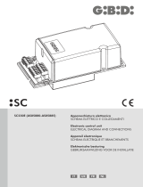
Manuale di installazione quadro elettrico per cancelli Obbi3BH a 1 o 2 motori 24 V=
Electric board installation handbook for Obbi3BH gate with 1 or 2 motors 24 V=
Manuel d'installation armoire électrique pour portails Obbi3BH à 1 our 2 moteurs 24 V=
Steuerung Montagehandbuch für Drehtore Obbi3BH mit 1 oder 2 Motoren 24 V=
Manual de instalaciòn cuadro electrico para cancelas Obbi3BH 1 o 2 motor 24 V=
F1
LN
BAT
F2
36
33
3134
15
1413 0
0
1156
8
9
TM
TC
TR
R1
POWER
SA
ON
SO
OM
OFF
RADIO / OPEN
24 V= / 0.3 A
-+
M2 M1
BATTERY KIT
BATK1
230 V~
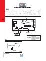
Q.E. D2H
1234
F1 = F1.6 A linea / line / secteur /
Leitung / linea
F2 = F2.5 A accessori / accessories /
accessoires / Zubehör /
accessorios
OM
36
33
31
4.5 A max
1 motore / 1 motor
34
M1
Fig. 2
Fig. 1
D2H
ISO 9001 - Cert. n° 0957/1

2
DITEC S.p.A. - IP1586 - D2H
AVVERTENZE GENERALI PER LA SICUREZZA
Il presente manuale di installazione è rivolto esclusivamente a personale professionalmente competente.
L’installazione, i collegamenti elettrici e le regolazioni devono essere effettuati nell’osservanza della Buona Tecni-
ca e in ottemperanza alle norme vigenti.
Leggere attentamente le istruzioni prima di iniziare l’installazione del prodotto. Una errata installazione può essere
fonte di pericolo.
I materiali dell’imballaggio (plastica, polistirolo, ecc.) non vanno dispersi nell’ambiente e non devono essere lasciati
alla portata dei bambini in quanto potenziali fonti di pericolo.
Prima di iniziare l’installazione verificare l’integrità del prodotto. Non installare il prodotto in ambiente e atmosfera
esplosivi: presenza di gas o fumi infiammabili costituiscono un grave pericolo per la sicurezza.
I dispositivi di sicurezza (fotocellule, coste sensibili, stop di emergenza, ecc.) devono essere installati tenendo in
considerazione: le normative e le direttive in vigore, i criteri della Buona Tecnica, l’ambiente di installazione, la
logica di funzionamento del sistema e le forze sviluppate dalla porta o cancello motorizzati.
Prima di collegare l’alimentazione elettrica accertarsi che i dati di targa siano rispondenti a quelli della rete
di distribuzione elettrica.
Prevedere sulla rete di alimentazione un interruttore/sezionatore onnipolare con distanza d’apertura dei contatti uguale
o superiore a 3 mm. Verificare che a monte dell’impianto elettrico vi sia un interruttore differenziale e una protezione
di sovracorrente adeguati.
Quando richiesto, collegare la porta o cancello motorizzati a un’efficace impianto di messa a terra eseguito come
indicato dalle vigenti norme di sicurezza. Durante gli interventi di installazione, manutenzione e riparazione, togliere
l’alimentazione prima di aprire il coperchio per accedere alle parti elettriche.
La manipolazione delle parti elettroniche deve essere effettuata munendosi di bracciali conduttivi antistatici
collegati a terra.
Il costruttore della motorizzazione declina ogni responsabilità qualora vengano installati componenti incompatibili
ai fini della sicurezza e del buon funzionamento.
Per l’eventuale riparazione o sostituzione dei prodotti dovranno essere utilizzati esclusivamente ricambi originali.
AVVERTENZE DI INSTALLAZIONE
Fissare il quadro elettrico in modo permanente. Forare il contenitore del quadro elettrico nel lato inferiore per il
passaggio dei cavi. Se accessibili, bloccare i cavi medianti opportuni pressacavi (non di nostra fornitura). Mantenere
separati di almeno 8 mm i conduttori di linea dai conduttori comandi e motore nei punti di connessione alle morsettiere
(per esempio con fascette). Richiudere il contenitore con le 4 viti posizionando correttamente il coperchio (lato inferiore
= privo di guarnizione).
Alimentazione
Uscita motore
Alimentazione accessori di sicurezza
(nominale)
(picco)
DATI TECNICI
Temperatura
Grado IP
Dimensioni
D2H
230 V~ / 50 Hz
24 V= / 2 x 4.5 A (max)
24 V= / 0.3A
24 V= / 0.5A
-15 °C / +50 °C
IP54
180x250x100
Tutti i diritti sono riservati
I dati riportati sono stati redatti e controllati con la massima cura. Tuttavia non possiamo assumerci alcuna responsabilità per eventuali
errori, omissioni o approssimazioni dovute ad esigenze tecniche o grafiche.
ITALIANO

3
DITEC S.p.A. - IP1586 - D2H
1. COLLEGAMENTI ELETTRICI
1.1 Comandi
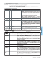
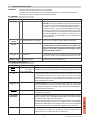
15N.O. PASSO-PASSO Con DIP1=OFF sequenza: “apre-stop-chiude-apre”.
Attenzione: se la chiusura automatica è abilitata lo STOP
non è permanente ma della durata impostata con TC.
Con DIP1=ON e chiusura automatica abilitata comando 1-5
= “apre”.
Con DIP1=ON e chiusura automatica non abilitata, a can-
cello fermo il comando 1-5 effettua la manovra opposta a
quella precedente all’arresto.
Nota: con contatto 1-5 permanente la chiusura automatica
viene disabilitata fino alla riapertura del contatto stesso.
16N.C. SICUREZZA D’ARRESTO Arresta e/o impedisce qualsiasi manovra.
18N.C. SICUREZZA DI INVERSIONE Inverte il movimento (riapertura) durante la chiusura. A can-
cello fermo e ponticello SO chiuso, impedisce qua-
lunque manovra, sia di apertura che di chiusura. A
cancello fermo e ponticello SO tagliato, impedisce solo
la manovra di chiusura.
19N.C. STOP Con contatto 1-9 aperto il cancello si ferma o rimane fermo
e la chiusura automatica viene disabilitata.
RADIO / OPEN PASSO-PASSO Ha la stessa funzione del contatto 1-5.
1.2 Uscite e accessori
1 + Alimentazione accessori. Uscita per alimentazione accessori esterni,
0- compresa lampada cancello aperto. Uscita protetta elettronicamente.
0 14 Lampeggiante (LAMPH). Si attiva durante la manovra di apertura e chiu-
sura. Per chiusura automatica, il lampeggio inizia 3 s prima della fine del
tempo impostato con TC; con TC minore di 3 s il prelampeggio dura per
tutto il tempo di sosta. Uscita protetta da fusibile F2.
0 15 Elettroserratura. Con elettroserratura da 12 V collegare in serie la resisten-
za da 8.2
ΩΩ
ΩΩ
Ω / 5 W. Si attiva all’inizio di ogni manovra di apertura. Con il DIP3
in ON è possibile abilitare il colpo di sblocco. Uscita protetta da fusibile F2.
1 13 Lampada cancello aperto. Accende una lampada che si spegne solo
a cancello chiuso.
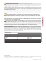
Collegamento Per cancelli a due ante collegare i motori come indicato in fig. 1.
motori N.B.: Invertire le polarità del motore in base al senso di apertura delle
ante. Per cancelli ad una anta tagliare il ponticello OM e collegare il
motore come indicato in fig. 2 . N.B.: Per allungare il cavo motore usare
2x1.5 mm² sino a 15 m, poi aumentare la sezione proporzionalmente alla
distanza.
BAT E’ previsto il collegamento di un kit batterie opzionale (BATK1, dotato di
circuito di controllo e carica batterie) per il funzionamento in modo conti-
nuità anche in assenza di tensione di linea.
ATTENZIONE Ponticellare tutti i contatti N.C. se non utilizzati.
I morsetti con numero uguale sono equivalenti.
La garanzia di funzionamento e le prestazioni dichiarate si ottengono solo con accessori e
dispositivi di sicurezza DITEC.
COMANDO
FUNZIONE
DESCRIZIONE
Uscita
Valore Descrizione
24V = / 0.3 A (nom.le)
0.5 A (picco)
24V = / 30 W max.
24V = / 1.2 A max.
24V = / 3 W max.
ITALIANO

4
DITEC S.p.A. - IP1586 - D2H
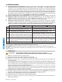
1.3 Selezioni e regolazioni
TC Tempo chiusura automatica. Da 0 a 120 s, con TC da 0 a 3/4 di giro. Il conteggio inizia da cancello fermo
per il tempo impostato con TC.
Con DIP2 = OFF, dopo l’intervento di una sicurezza (1-6 / 1-8), il conteggio inizia al rilascio della sicurezza stessa
(ad esempio dopo il passaggio attraverso le fotocellule), e dura per la metà del tempo impostato con TC.
Con DIP2=ON il conteggio inizia a cancello aperto e dura per tutta la durata del tempo impostato su TC.
Con TC al massimo o contatto 1-9 aperto la chiusura automatica è disabilitata. Se disabilitata da 1-9, la
chiusura automatica si riabilita, una volta richiuso il contatto 1-9, solo dopo un comando 1-5.
TM Tempo massimo manovra. Da 10 a 90 s con TM dal minimo al massimo.
TR Regolazione del tempo di ritardo in chiusura del motore 1. Da 0 a 30 s con TR dal minimo al massi-
mo. In apertura il motore 2 (M2) parte sempre con 3 s di ritardo rispetto a M1. In chiusura il motore 1 (M1)
parte con un ritardo regolabile con TR rispetto a M2.
R1 Regolazione spinta sugli ostacoli. Il quadro elettrico è dotato di un dispositivo di sicurezza che arresta il
movimento di apertura/chiusura in presenza di un ostacolo. Con R1 al minimo si ha la minima forza e la
massima sensibilità agli ostacoli. Con R1 al massimo si ha la massima forza e la minima sensibilità agli
ostacoli.
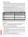
DIP1
DIP2
DIP3
DIP4
(*)
SO
OM
OFF /
ON /
Funzionamento comando 1-5 = passo-passo Funzionamento comando 1-5 = apre
Rinnovo tempo chiusura automatica = 50% Rinnovo tempo chiusura automatica = 100%
Sblocco elettroserratura = disabilitato Sblocco elettroserratura = abilitato
Stato del cancello all’accensione = cancello aper-
to: il primo comando 1-5 effettua la chiusura (N.B.:
Con DIP1=ON e TC non al massimo, il primo co-
mando è esclusivamente la chiusura automatica).
Stato del cancello all’accensione = cancello chiu-
so: il primo comando 1-5 effettua l’apertura (N.B.:
La chiusura automatica non può essere il primo co-
mando, anche se abilitata).
Funzionamento sicurezza 1-8: l’apertura del con-
tatto 1-8 a cancello fermo consente l’apertura me-
diante comando 1-5.
Funzionamento sicurezza 1-8: l’apertura del con-
tatto 1-8 a cancello fermo impedisce qualsiasi ma-
novra.
Numero ante: cancello 1 anta.Numero ante: cancello 2 ante.
(*) il DIP4 indica come il quadro elettronico considera il cancello al momento dell’accensione (oppure al ritorno di
alimentazione dopo una interruzione), indipendentemente dalla reale posizione delle ante del cancello stesso.
LED POWER. Acceso indica che il quadro è alimentato.
LED SA. Acceso indica che almeno uno dei contatti 1-6, 1-8 (sicurezze) o 1-9 (stop) è aperto.
2. AVVIAMENTO
ATTENZIONE Le manovre relative al punto 2.4 avvengono senza sicurezze.
E’ possibile variare i trimmer solo a cancello fermo.
2.1 Posizionare manualmente le ante del cancello in posizione di chiusura.
2.2 Se il cancello è a una anta tagliare il ponticello OM.
2.3 Impostare TC e R1 al massimo. Ponticellare le sicurezze e lo stop.
2.4 Dare alimentazione (N.B.: Invertire le polarità del motore in base al senso di apertura delle ante).
In presenza di fermi battuta in apertura, regolare il trimmer TM in modo da avere un tempo manovra di 2-3
s maggiore del tempo impiegato dal cancello per aprire completamente.
In mancanza di fermi battuta in apertura, regolare il trimmer TM in modo da ottenere l’apertura desiderata.
Regolare il trimmer TR in modo che le ante si richiudano sovrapponendosi correttamente (anche in caso di inversio-
ne). Controllare il corretto funzionamento del cancello con successivi comandi passo-passo (apre-stop-chiude).
2.5 Togliere i ponticelli e collegare i comandi, le sicurezze (1-6 e 1-8) e lo stop (1-9) e verificarne il funzionamento.
2.6 Se desiderato, regolare con TC la chiusura automatica. Attenzione: il tempo di chiusura automatica dopo
l’intervento di una sicurezza dipende dall’impostazione del DIP2.
2.7 Impostare con R1 la spinta sugli ostacoli.
2.8 Collegare gli eventuali accessori e verificarne il funzionamento.
2.9 Richiudere il contenitore con le 4 viti posizionando correttamente il coperchio (lato inferiore = privo di
guarnizione).
ITALIANO

5
DITEC S.p.A. - IP1586 - D2H
GENERAL SAFETY PRECAUTIONS
This installation manual is intended for professionaly competent personnel only.
The installation, the electrical connections and the settings must be completed in conformity with good workman-
ship and with the laws in force. Read the instructions carefully before beginning to install the product. Incorrect
installation may be a source of danger.
Packaging materials (plastics, polystyrene, etc) must not be allowed to litter the environment and must be kept
out of the reach of children for whom they may be a source of danger. Before beginning the installation check that
the product is in perfect condition.
Do not install the product in explosive areas and atmospheres: the presence of flammable gas or fumes repre-
sents a serious threat to safety. The safety devices (photoelectric cells, mechanical obstruction sensor, emer-
gency stop, etc) must be installed taking into account: the provisions and the directives in force, good workman-
ship criteria, the installation area, the funtional logic of the system and the forces developed by the motorised door
or gate.
Before connecting to the mains check that the rating is correct for the destination power requirements.
A multipolar isolation switch with minimum contact gaps of 3 mm must be included in the mains supply.
Check that upstream of the electrical installation there is an adequate differential switch and a suitable circuit
breaker.
When requested, connect the motorized door or gate to an effective earthing system carried out as indicated by
current safety standards. During installation, maintenance and repair operations, cut off the power supply before
opening the cover to access the electrical parts.
The electronic parts must be handled using earthed antistatic conductive arms. The manufacturer of the motorising
device declines all responsability in cases where components which are incompatible with the safe and correct
operation of the product only original spare parts must be used. For repairs or replacements of products only original
spare parts must be used. The fitter must supply all information corcerning the automatic, the manual and emergency
operation of the motorised door or gate, and must provide the user the device with the operating instructions. It is
recommended that antistatic conductive earthed arm bands be worn when manipulating electronic parts.
INSTALLATION WARNING
Secure the electric board permanently. Drill the lower side of the container so as to run the cables through it.
Secure the cables, if they are accessible, by means of appropriate gland plates (not provided by us). Keep the line
conductors separate (at least 8 mm.) from the control conductors and motor at the terminal board connection
points (for example, by means of clamps). Re-close the container by means of the 4 screws, taking care to
properly position the cover (lower side = Devoid of gasket).
Power supply
Motor output
Safety accessories power supply
(nominal)
(peak)
TECHNICAL DATA
Temperature
Degree IP
Dimensions
D2H
230 V~ / 50 Hz
24 V= / 2 x 4.5 A (max)
24 V= / 0.3A
24 V= / 0.5A
-15 °C / +50 °C
IP54
180x250x100
All right reserved
All data and specifications have been drawn up and checked with the greatest care. The manufacturer cannot however take any
responsibility for eventual errors, ommisions or incomplete data due to technical or illustrative purposes
ENGLISH

6
DITEC S.p.A. - IP1586 - D2H
1. ELECTRICAL CONNECTION
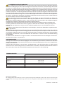
1.1 Controls
15N.O. STEP BY STEP When DIP1 = OFF sequence:“Open-Stop-Close-Open”.
Warning: if the automatic closure is enabled, the stop is
not permanent but lasts for the time set by means of TC.
When DIP1 = ON and automatic closing is activated, con-
tact 1-5 = “Open”.
When DIP1 = ON and automatic closing is deactivated,
contact 1-5 executes the opposite movement of the one
that was executed prior to stopping when the gate is stand-
ing still. Note: with permanent contact 1-5, the automatic
closing is disabled until the contact reopens.
16N.C. STOPPING SAFETY CONTACT It stops or prevents the any operation.
18N.C. REVERSAL SAFETY CONTACT Reverses the direction of movement during the closing
maneuver (opens the gate again). When the gate is
standing still and bridge SO is closed, every movement
– both opening and closing – is prevented. When the
gate is standing still and bridge SO is interrupted, only
the closing maneuver is prevented.
19N.C. STOP With the 1-9 contact, the gate stops or stays stopped and
automatic closing is disabled.
RADIO / OPEN STEP BY STEP It has the same function as contact 1-5.
1.2 Outputs and accessories
1 + Accessories power supply. Output for power external accessories
0- including the door-open signal lamp. Electronically-protected exit.
0 14 Flashing light (LAMPH). It is activated during the opening and closing
movements. During an automatic closing procedure the blinking phase
begins 3 s before the time set on TC expires; if TC is set to less than 3 s, the
preliminary blinking phase continues throughout the entire standstill time.
Protected exit with fuse F2.
0 15 Electric lock. In connection with an electric lock having 12V the resistance
of 8.2 Ohm/5 W is connected in series. It is activated at the beginning of
every opening movement. When DIP 3 = ON, the release can be activated.
Protected exit with fuse F2.
1 13 Light „Gate open“. Activates a light that goes out only when the gate is
closed.
Motor When there are double-leaf gates, connect the motors according to Fig.
connection 1. Note: Depending on the direction of opening of the leaves of the gate,
the polarity of the motor may have to be reversed.
When there are single-leaf gates, bridge OM has to be interrupted and
the motor should be connected according to Fig. 2. Note: If it is neces-
sary to lengthen the motor cable, use 2x1.5 mm² up to a length of 15 m;
then increase the cross-section proportionally to the distance.
BAT This connection is provided for connecting an optional emergency battery
(BATK1, equipped with a control circuit and charging device) to ensure
that the opening system functions in the event of a power failure.
WARNING: Link up all N.C. contacts (if not used) by means of jumpers.
The terminal bearing the same number are equivalent.
The given operating and performance features can only be guaranteed with the use of DITEC
accessories and safety devices.
CONTROL
FUNCTION
DESCRIPTION
Output
Value Description
24V = / 0.3 A (nominal)
0.5 A (peak)
24V = / 30 W max.
24V = / 1.2 A max.
24V = / 3 W max.
ENGLISH

7
DITEC S.p.A. - IP1586 - D2H
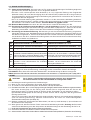
1.3 Settings and adjustment
TC Automatic closure time. From 0 to 120 s when TC is set from 0 to 3/4 rotations. The counting begins
when the gate is closed and continues throughout the entire duration of time set on TC.
When DIP2 = OFF and after response of a safety device (1-6/1-8), the counting begins after the safety device
itself is released (e.g. after passing through the light barrier) and takes half as long as the time set on TC.
With DIP2=ON the count begins when the gate is open and lasts for the entire length of time set on TC.
When TC is in the maximum position or contact 1-9 is open, the automatic closing procedure is deactivated.
When the deactivation is executed via 1-9, the automatic closing procedure will only be activated again after
contact 1-9 is closed again, if command 1-5 is given.
TM Maximum operating time. From 10 to 90 s when TM is set between minimum and maximum setting.
TR Setting for the delay time of motor 1 during the closing procedure. From 0 to 30 s when TR is set
between minimum and maximum. During the opening procedure motor 2 (M2) always starts 3s after M1.
During the closing procedure motor 1 (M1) is started after M2, with such delay being set via TR.
R1 Obstacle detection adjustment. The control unit must be equipped with a safety device that interrupts the opening
or closing procedure when an obstacle is detected. When R1 is set to minimum, the system exhibits minimum
power and maximum sensitivity with respect to obstacles. When R1 is in the maximum setting, the system exhibits
maximum power and minimum sensitivity with respect to obstacles.
(*) DIP4 indicates the condition, in which the control unit considers the gate to be when the motor is switched on (or
when the power supply is restored after a power failure) irrespective of the actual position of the leaves of the gate.
LED POWER. When this LED lights up, it means that the control unit is being supplied with power.
LED SA. When this LED lights up, it means that at least one of the contacts 1-6, 1-8 (safety devices) or 1-9 (Stop) is open.
2. START
CAUTION: The movements described in 2.4 are executed without any safety devices.
The trimmers can only be adjusted when the gate is standing still.
2.1 Close the leaves of the gate manually.
2.2 In case of a single-leaf gate, interrupt bridge OM.
2.3 Set TC and R1 to the maximum settings. Bypass safety devices and stop.
2.4 Switch on the power supply. (Note: Depending on the direction of opening of the leaves, the polarity of the motor may
have to be reversed.). When the opening maneuver is defined by a limit stop, trimmer TM should be set in such a way
that the time of the moving procedure takes 2-3 s longer than the time required for the gate to be opened completely.
When the opening maneuver is not defined by a limit stop, trimmer TM should be set in such a way that the desired
distance of opening is reached. Set trimmer TR in such a way that the leaves of the gate close again by folding over
one another correctly (also when the direction is reversed). Check that the gate is functioning correctly by means of
consecutive step commands (Open-Stop-Close).
2.5 Interrupt bridges, connect the contacts, safety devices (1-6 and 1-8) as well as the stop (1-9) and check
whether everything is functioning correctly.
2.6 If necessary, set the automatic closing procedure via trimmer TC. Attention: The time for the automatic
closing procedure after the safety device has responded depends on the setting selected for DIP2.
2.7 Set the sensitivity of the obstacle recognition by means of R1.
2.8 Connect any accessories, if applicable, and check whether they function correctly.
2.9 Re-close the container by means of the 4 screws, taking care to properly position the cover (lower side =
Devoid of gasket).
DIP1
DIP2
DIP3
DIP4
(*)
SO
OM
OFF /
ON /
Command 1-5 functioning = step by step Command 1-5 functioning = opens
Resetting the automatic closing time = 50% Resetting the automatic closing time = 100%
Electric lock release = disabled Electric lock release = abled
Condition of the gate when the motor is switched on
= gate open: the first command 1-5 executes a closing
procedure. (Note: When DIP1 = ON and TC is not set to
the maximum setting, the first command executes only
the automatic closing procedure).
Condition of the gate when the motor is switched
on = gate closed: the first command 1-5 executes
an opening procedure. (Note: The automatic clos-
ing procedure may not be the first command, even if
it is activated).
Safety device 1-8 functioning: opening contact 1-
8 permits an opening procedure via command 1-5
when the gate is standing still.
Safety device 1-8 funtioning: opening contact 1-8
prevents any kind of maneuver when the gate is
standing still.
Number of leaves: Gate with one leaf.Number of leaves: Gate with two leaves.
ENGLISH

8
DITEC S.p.A. - IP1586 - D2H
CONSIGNES GENERALES DE SECURITE
Cette notice d’installation est destinée exclusivement aux professionnels qualifiés. L’installation, le
raccordement électrique et les réglages doivent être effectuée selon les régles de Bonne Tecniques er respecter
la réglementation en vigueur.
Lire attentivement les instructions avant de procéder à l’installation du produit. Une instalaltion erronée peut être
source de danger.
Les materiaux de l’emballage (plastique, polystyréne, etc) ne doivent pas être abandonnées dans la nature et ne
doivent pas être laissés à la portée des enfants, car ils sont une source potentielle de danger. Avant de procéder
à l’installation, vérifier l’integrité du produit.
Ne pas installer le produit à proximité de matières explosives: la présence de gaz ou de vapeurs inflammables
représente un grave danger pour la securité. Le dispositifs de securité (photocellules, barres palpeuses, arrêt
d’urgence, etc) doivant être installés en tenant compte des normes et directives en vigueur, des critéres de Bonne
Technique, de l’emplacement de l’installation, de la logique de fonctionement du systéme et des forces dégagées
par la porte ou le portail équipés d’automatismes.
Avant de procéder au raccordement électrique, s’assurer que les données de la plaquette signalétique correspondent
à celles du réseau d’alimentation électrique. Prévoir sur le réseau d’alimentation un dispositif de coupure omnipolaire
avec une distance d’ouverture des contacts égale ou supérieure à 3 mm. Vérifier qu’en amont de l’installation électrique il y
ait un interrupteur différentiel ainsi qu’une protection contre des surchanges de courant adèquate. Quand cela est demandé,
relier la porte ou le portail motorisés à une installation efficace de mise à la terre selon ce qui est indiqué par les
dispositions de sécurité en vigueur. Pendant les interventions d’installation, d’entretien et de réparation, couper
l’alimentation avant d’ouvrir le couvercle d’accès aux parties électriques.
La manipulation des parties électroniques doit se faire en portant des brassards conductibles
antistatiques reliés à la terre.
Le costructeur des automatismes décline toute responsabilité au cas où seraient installés des composants
incompatibles en termes de seécurite et de bon fonctionnement.
En cas de réparation ou de remplacement des produits, les pièces de rechange originales doivent impérativement être
utilisées.
L’installateur doit fournir tous les renseignements concernant le fonctionement automatique, manuel ou de secours
de la porte ou du portail automatisés et remettre la notice d’emploi à l’utilisateur.
La manipulation des parties électroniques doit être effectuèe en mettant des bracelets conducteurs antistatiques
reliés à la terre.
CONSEILS POUR L’INSTALLATION
Fixer le coffret électrique à demeure. Percer la caisse du coffret électrique dans la partie inférieure pour le passage des
câbles. S”ils sont accessibles, bloquer les câbles au moyens de serre-câbles prévus à cet effet (non fournis). Maintenir
séparés (d’au moins 8 mm) les conducteurs de ligne d’avec les conducteurs commandes et moteur dans les points de
connexions aux boîtes à borne (au moyen de colliers, par exemple). Refermer le récipient au moyen des 4 vis en
mettant en place correctement le couvercle (côté inférieur = depourvu de garniture).
Alimentation
Sortie moteur
Alimentation accessoires de securité
(nominale)
(max)
DONNEES TECHNIQUES
Temperature
Degré IP
Dimensions
D2H
230 V~ / 50 Hz
24 V= / 2 x 4.5 A (max)
24 V= / 0.3A
24 V= / 0.5A
-15 °C / +50 °C
IP54
180x250x100
Touts droits reservés
Les informations mentionnées dans ce catalogue ont été controlées avec la plus grande attention. Toutefois, nous déclinos toute
responsabilité en cas d’erreurs, omissions ou approximations dépendant d’exigences techniques ou graphiques.
FRANÇAIS

9
DITEC S.p.A. - IP1586 - D2H
1. RACCORDEMENTS ELECTRIQUES
1.1 Commandes
15N.O. PAS A PAS Quand DIP1 = OFF Séquence : “Ouvre-Stop-Ferme-Ouvre”.
Attention: si la fermeture automatique est activée, l’arrêt n’est
pas permanent mais de durée égale à la valeur fixée par TC.
Quand DIP1 = ON et fermeture automatique activée, contact
1-5 = “ouvrir”. Quand DIP1 = ON et fermeture automatique
désactivée, le contact 1-5 exécute, le portail étant immobile,
le mouvement opposé à celui effectué avant l’arrêt.
Nota: le contact 1-5 étant permanent, la fermeture
automatique est désactivée jusqu’à la réouverture du contact.
16N.C. SECURITE D’ARRET Interrompt et / ou empêche tout mouvement.
18N.C. SECURITE D’INVERSION Invers le mouvement (réouverture) pendant la fermeture.
Lorsque le portail est immobile et que le pont SO est
fermé, chaque mouvement, tant l’ouverture que la fer-
meture, est empêché. Lorsque le portail est immobile
et que le pont SO est interrompu, seule la manœuvre
de fermeture est empêchée.
19N.C. ARRET Lorsque le contact 1-9 est ouvert, le portail s’arrête ou reste
arrête. La fermeture automatique est désactivée.
RADIO / OPEN COMMANDE PAS À PAS Fonction identique au contact 1-5.
1.2 Sorties et accessoires
1 + Alimentation des accessoires. Sortie pour l’alimentation accessoires extérieurs
0- y compris lampe “ portail ouvert”. Sortie protégée électroniquement.
0 14 Lampe clignotante (LAMPH). S’active en même temps que la
manoeuvre d’ouverture et de fermeture. Lors de la fermeture automati-
que, la phase clignotante commence 3 s avant écoulement du temps
réglé au niveau du TC ; si le TC est réglé pour moins de 3 s, la phase de
préclignotement dure pendant toute la durée de l’immobilisation. Sortie
protégée avec fusible F2.
0 15 Verrou électrique. Pour un verrou électrique de 12 V, monter en série
une résistance de 8.2 Ohm / 5 W. Est activé au début de chaque
mouvement d’ouverture. Quand DIP 3 = ON, le déverrouillage est activé.
Sortie protégée avec fusible F2.
1 13 Lampe “portail ouverte”. Active une lampe qui ne s’eteint que lorsque
le portail est fermée.
Raccordement Pour les portails à deux vantaux, raccorder les moteurs selon Fig. 1.
du moteur N.B.: la polarité du moteur doit être inversée en fonction du sens d’ouver-
ture des vantaux. Pour les portails à un vantail, le pont OM doit être interrompu
et le moteur raccordé selon Fig. 2. N.B.: pour prolonger le câble du moteur
utiliser une section de 2x1.5 mm² pour une longueur jusqu’à 15 m. Accroître
ensuite la section proportionnellement à l’éloignement.
BAT Raccordement d’une batterie de secours en option (BATK1, équipée
d’un circuit de commande et d’un chargeur) pour assurer le
fonctionnement en cas de panne de courant.
ATTENTION Ponter tous les contacts N.C. s’ils ne sont pas utilisés.
Les bornes ayant le même numéro sont équivalentes
La garantie de fonctionnement et les performances spécifiées ne s’obtiennent qu’avec les
accessoires et les dispositifs de sécurité DITEC.
COMMANDE
FONCTION
DESCRIPTION
FRANÇAIS
Sorties
Valeur Description
24V = / 0.3 A (nominal)
0.5 A (max)
24V = / 30 W max.
24V = / 1.2 A max.
24V = / 3 W max.

10
DITEC S.p.A. - IP1586 - D2H
1.3 Selection et reglages
TC Temps de fermeture automatique. De 0 à 120 s, pour TC de 0 à 3/4 de tours. Le comptage commence
lorsque le portail est arrête, pendant toute la durée réglée sur le TC. Quand DIP2 = OFF, après réaction d’une
sécurité (1-6 / 1-8), le comptage commence après libération de cette sécurité (p. ex. après le passage de la
barrière photoélectrique) et dure moitié moins de temps que le temps réglé sur le TC. Commutateur DIP2
étant sur ON, le comptage commence à grillage ouvert et dure pour toute la durée du temps paramétré sur
TC. Lorsque le TC est en position maximale ou que le contact 1-9 est ouvert, la fermeture automatique est
désactivée. Lorsque la désactivation se produit par 1-9, la fermeture automatique n’est réactivée après
nouvelle fermeture du contact 1-9, que lorsque la commande 1-5 a été donnée.
TM Durée maximale de mise en circuit du moteur. De 10 à 90 s du réglage minimal au réglage maximal du TM.
TR Réglage du temps de retard du moteur 1 lors de la fermeture. De 0 à 30 s du réglage minimal au
réglage maximal du TR. A l’ouverture, le moteur 2 (M2) démarre toujours 3 s plus tard que M1. A la
fermeture, le moteur 1 (M1) démarre avec un retard réglable via TR par rapport à M2.
R1 Réglage du dispositif de detection d’obstacles. La commande est dotée d’un dispositif de sécurité qui
interrompt le mouvement d’ouverture, resp. de fermeture lorsqu’un obstacle survient. Lorsque R1 est réglé sur
le minimum, on obtient la force minimale et la sensibilité maximale au niveau des obstacles. Lorsque R1 est
réglé sur le maximum, on obtient la force maximale et la sensibilité minimale au niveau des obstacles.
DIP1
DIP2
DIP3
DIP4
(*)
SO
OM
OFF /
ON /
Fonctionnement commande 1-5 = pas à pas. Fonctionnement commande 1-5 = ouvre
Renouvellement du temps de fermeture autom. = 50% Renouvellement du temps de fermeture autom. = 100%
Déverrouillage verrou électrique = désactivé Déverrouillage verrou électrique = activé
État du portail à l’activation = portail ouvert : la première
commande 1-5 exécute la fermeture (N.B. quand DIP1 =
ON et que le TC n’est pas en position maximale, la première
commande est automatiquement la fermeture automatique).
État du portail à l’activation = portail fermé: la pre-
mière commande 1-5 exécute l’ouverture (N.B. : la
fermeture automatique ne doit pas être la première
commande, même si elle est activée).
Mode de fonctionnement sécurité 1-8: l’ouverture
du contact 1-8 lorsque le portail est immobile per-
met l’ouverture par la commande 1-5.
Mode de fonctionnement sécurité 1-8: l’ouverture
du contact 1-8 lorsque le portail est immobile empê-
che toute manœuvre.
Nombre de vantaux: portail avec un vantailNombre de vantaux: portail avec deux vantaux
(*) DIP4 montre comment la commande considère le portail au moment de l’activation (ou au retour du courant en
cas d’interruption), indépendamment de la position effective des vantaux.
LED POWER. Lorsque cette LED est allumée, ceci signifie que la commande est alimentée en électricité.
LED SA. Lorsque cette LED est allumée, ceci signifie qu’au moins un des contacts 1-6, 1-8 (sécurités) ou 1-9
(Stop) est ouvert.
2. DÉMARRAGE
ATTENTION Les mouvements décrits sous le point 2.4 se font sans sécurités.
Les parametres ne peuvent être ajustés que lorsque le portail est immobile.
2.1 Mettre les vantaux de portail en position fermée.
2.2 S’il s’agit d’un portail à un vantail, interrompre le pont OM.
2.3 Régler TC et R1 sur le maximum. Ponter les sécurités et le stop.
2.4 Brancher le courant. (N.B. : la polarité du moteur doit être inversée en fonction du sens d’ouverture des
vantaux du portail).
En cas de présence d’un butoir de stoppage pour l’ouverture, le potentiometre ajustable TM est réglé de sorte à ce
que le mouvement dure 2-3 s plus longtemps que le temps dont a besoin le portail pour s’ouvrir complètement.
En cas d’absence d’un butoir de stoppage pour l’ouverture, le potentiometre ajustable TM est réglé de
manière à ce que l’ouverture souhaitée soit réalisée.
Régler le potentiometre ajustable TR de manière à ce que les vantaux de portail se referment en s’étageant
correctement (même pour l’inversion de sens). Vérifier le fonctionnement correct du portail avec des com-
mandes pas à pas successives (ouvert-stop-fermé).
2.5 Interrompre les ponts, raccorder les contacts, les sécurités (1-6 et 1-8) ainsi que le stop (1-9) et vérifier le fonctionnement.
2.6 Si souhaité, régler la fermeture automatique via le potentiometre ajustable TC. Attention: le temps pour la
fermeture automatique après la réaction de la sécurité dépend du réglage du DIP 2.
2.7 Régler avec R1 la sensibilité de la reconnaissance d’obstacles.
2.8 Raccorder d’éventuels accessoires et vérifier le fonctionnement.
2.9 Refermer le récipient au moyen des 4 vis en mettant en place correctement le couvercle (côté inférieur =
depourvu de garniture).
FRANÇAIS

11
DITEC S.p.A. - IP1586 - D2H
ALLGEMEINE SICHERHEITSHINWEISE
Das vorliegende Installationhandbuch ist ausschliesslich für das Fachpersonal bestimmt. Montage, elektrische
Anschlüsse und Regelungen sind auf der Grundlage der bestehenden Vorschriften nache den Regeln der Technik
auszüfuhren. Vor Einbaubeginn sind die Anweisungen sorgfältig durchzulesen. Falcher Einbau kann Gefahr mit
sich bringen. Das Verpackungsmaterial (Kunststoff, Polystyrol usw.) ist vorschriftsmäßig zu entsorgen. Es ist von
Kindern fernzuhalten, da es eine Gefahr für si bedeutet. Vor Beginn der Montage ist der einwandfreie Zustand des
Produkts zu überprüfen. In explosionsgefährdeten Bereichen darf das Produkt nicht eingebaut werden: Entzündbare
Gase oder Rauch stellen eine ernsthafte Sicherheitsgefährdung dar. Die Sicherheitseinrichtungen (Photozellen,
Lichtschranken, Nothalteinrichtungen usw.) sind nach den Regeln der Technik so zu installieren, daß die geltenden
Vorschriften und Richtlinien eingehalten sowie Einbauort, Betriebsweise des Antriebssystems und die Kräfte, die
das Tor beim Antrieb aufweist, berücksichtigt werden.
Vor dem Netzanschluß ist sicherzustellen, daß die Daten auf dem Typenschild mit denen des
Stromversorgungsnetzes übereinstimmen. Netzsetig ist ein Allpoll-Schalter bzw. -Trennschalter mit Abstand
der Kontakte in geöffneter Stellung > oder = 3 mm vorzusehen. Es ist sicherzustellen, daß der Elektroanlage die
erforderlichen FI-Schalter und Überstromschutzschalter vorgeschaltet sind.
Gegebenenfalls ist die motorisierte Tür oder das Tor an eine wirksame Erdungsanlage anzuschließen, die
nach den geltenden Sicherheitsvorschriften ausgeführt ist. Während der Installation, Wartung und Reparatur
ist die Anlage vom Stromnetz zu nehmen, bevor der Deckel geöffnet wird, um an die elektrischen Teile zu
kommen.
Arbeiten an den elektronischen Teilen dürfen nur mit leitfähigen, antistatischen Armbändern ausgeführt werden,
die geerdet sind.
Der Hersteller des Antriebs lehnt jede Verantwortung ab, wenn beim Einbau Teile montiert werden, die weder den
Sicherheitsanforderungen noch einem ordungsgemäßen Betrieb entsprechen. Bei Reparatur und Austausch sind
ausschließlich Originalersatzteile zu verwenden. Der Einbaubetrieb ist verpflichtet, dem Benutzer alle notwendigen
Informationen für Automatik-, Hand- und Notbetrieb des Torantriebs zu liefern und ihm die Betriebanleitung
auszuhändigen.
Die Elektronischen Teile dürfen nur angefasst werden, wenn die betreffende Person mit Leitfähigen antistatischen,
geerdeten Manschetten ausgestattet ist.
MONTAGEHINWEISE
Befestigen Sie die elektrische Schalttafel endgültigen. Für die Kabelführung das Gehäuse der elektrischen Schalttafel
auf der Unterseite bohren. Falls erhältlich, die Kabel unter Verwendung geeigneter (nicht von uns mitgelieferter)
Kabelpressen blockieren.
Halten Sie die Leitungskabel von den Steuer- und Motorkabeln an den Anschlusspunkten im Klemmenbrett
mindestens 8 mm voneinander getrennt (z.B. Kabelschellen verwenden). Schließen Sie den Behälter wieder mit
den 4 Schrauben, indem Sie den Deckel korrekt positionieren (Unterseite = Ohne Dichtung).
Netzanschluß
Motor Ausgange
Sicherheits-Zubehöre Stromzufuhr
(Nominal)
(Spitze)
TECHNISCHE DATEN
Temperatur
Schutzgrad
Abmessungen
D2H
230 V~ / 50 Hz
24 V= / 2 x 4.5 A (max)
24 V= / 0.3A
24 V= / 0.5A
-15 °C / +50 °C
IP54
180x250x100
Alle Rechte vorbehalten
Die wiedergegebenen Daten wurden mit höchster Sorgfalt zusammengestellt und überprüft. Es kann jedoch keinerlei Verantwortung für
eventuelle Fehler, Auslassungen oder Näherungen, die technischen oder graphischen Notwendigkeiten zuzuschreiben sind, übernommen
werden.
DEUTSCH

12
DITEC S.p.A. - IP1586 - D2H
1. ELEKTRISCHE ANSCHLUSSE
1.1 Steurungen
15N.O. SCHRITTSTEUERUNG Bei DIP1 = OFF Sequenz: “Auf-Stop-Zu-Auf”.
Achtung: wenn die automatische Schließung aktiviert ist,
dauert die Haltezeit nur solange, wie am TC eingegeben wurde.
Bei DIP1 = ON und aktivierter automatische Schließung,
Kontakt 1-5 = “öffnen”. Bei DIP1 = ON und deaktivierter
automatischer Schließung führt der Kontakt 1-5 bei
stillstehendem Tor die entgegengesetzte Bewegung zu der
aus, die vor dem Anhalten durchgeführt wurde.
Hinweis: Bei permanenter Einstellung des Kontakts 1-5 wird
die automatische Schließung bis zur erneuten Öffnung des
Kontakts deaktiviert.
16N.C. ANHALTESICHERHEIT Stoppt und/oder verhindert jegliche Bewegung.
18N.C. UMKEHRSICHERHEIT Kehrt die Öffnungbewegung um (Wiederöffnung). Bei
stillstehendem Tor und geschlossener Brücke SO wird jede
Bewegung - sowohl Öffnung als auch Schließung -
verhindert. Bei stillstehendem Tor und unterbrochener
Brücke SO wird nur die Schließbewegung verhindert.
19N.C. STOPP Bei offenem Kontakt 1-9 schließt sich das Tor oder bleibt
geschlossen. Die automatische Schließung wird deaktiviert.
RADIO / OPEN SCHRITTSTEUERUNG Gleiche Funktion wie Kontakt 1-5.
1.2 Ausgänge und Zubehör
1 + Stromversorgung Zubehör. Ausgang für Stromversorgung des Zube-
0- hörs und Lampe Tor offen. Elektronisch geschützter Ausgang.
0 14 Blinklicht (LAMPH). Wird gleichzeitig mit dem Öffnungs- und dem
Schließmanöver aktiviert. Bei der automatischen Schließung beginnt die
Blinkphase 3 s vor Ablauf der am TC eingestellten Zeit; wenn TC unter 3
s eingestellt ist, dauert die Vorblinkphase während der gesamten
Stillstandszeit an. Mit Sicherung geschützter Ausgang (F2).
0 15 Elektroschloß. Bei einem Elektroschloß von 12 V Widerstand von 8.2
Ohm/5 W in Reihe schalten. Wird zu Beginn jeder Öffnungsbewegung
aktiviert. Bei DIP 3 = ON kann die Entriegelung aktiviert werden. Mit
Sicherung geschützter Ausgang (F2).
1 13 Lampe Tor offen. Aktiviert eine Lampe, die erst bei geschlossenem Tor
ablöscht.
Motoranschluß Bei zweiflügeligen Toren Motoren gemäß Abb. 1 anschließen. N.B.: Je nach
Öffnungsrichtung der Torflügel muß die Polarität des Motors umgekehrt werden.
Bei einflügeligen Toren muß die Brücke OM unterbrochen und der Mo-
tor gemäß Abb. 2. N.B.: Zum Verlängern des Motorkabels 2x1.5 mm² bis
zu einer Länge von 15 m verwenden. Dann den Querschnitt proportional zur
Entfernung erhöhen.
BAT Der Anschluß eines optionalen Notakkus (BATK1, ausgestattet mit einem
Steuerkreis und Ladegerät) zur Gewährleistung der Funktion bei
Stromausfall ist vorgesehen.
ACHTUNG Alle N.C. Kontakte überbrücken, wenn sie nicht gebraucht werden
Die Klemme mit derselben Nummer sind Äquivalent.
Die Funktionsgarantie und die angegebenen Leistungen werden nur mit Zubehör und Sicherheits-
vorrichtungen von DITEC erzielt.
STEUERUNG
FUNKTION
BESCHREIBUNG
Ausgang
Wert Beschreibung
24V = / 0.3 A (Nominal)
0.5 A (Spitze)
24V = / 30 W max.
24V = / 1.2 A max.
24V = / 3 W max.
DEUTSCH

13
DITEC S.p.A. - IP1586 - D2H
1.3 Anwahl und Einstellungen
TC Automatische Schließzeit. Von 0 bis 120 s, bei TC von 0 bis 3/4 Umdrehungen. Die Zählung beginnt bei
geschlossenem Tor über die gesamte, am TC eingestellte Zeitdauer.
Bei DIP2 = OFF, nach Ansprechen einer Sicherheit (1-6 / 1-8), beginnt die Zählung nach Freigabe der
Sicherheit selbst (z.B. nach dem Durchgang durch die Lichtschranke) und dauert halb so lang wie die am
TC eingestellte Zeit. Bei DIP2=ON beginnt die Zählung bei geöffnetem Tor und wird für den auf dem TC
eingestellten Zeitraum fortgesetzt.
Bei TC in maximaler Stellung oder geöffnetem Kontakt 1-9 ist die automatische Schließung deaktiviert.
Wenn die Deaktivierung über 1-9 erfolgt, wird die automatische Schließung nach dem erneuten Schließen
des Kontaktes 1-9 erst dann wieder aktiviert, wenn der Befehl 1-5 gegeben wurde.
TM Maximale Motorlaufzeit. Von 10 bis 90 s bei minimaler bis maximaler Einstellung von TM.
TR Einstellung der Verzögerungszeit des Motors 1 bei der Schließung. Von 0 bis 30 s bei minimaler bis
maximaler Einstellung von TR. Bei der Öffnung startet der Motor 2 (M2) immer 3 s später als M1. Bei der
Schließung startet Motor 1 (M1) mit einer über TR einstellbaren Verzögerung gegenüber M2.
R1 Einstellung der Hinderniserkennung. Die Steuerung ist mit einer Sicherheitsvorrichtung ausgestattet,
welche die Öffnungs- bzw. Schließbewegung bei Auftreten eines Hindernisses unterbricht. Wenn R1 auf
das Minimum eingestellt ist, erhält man die minimale Kraft und die maximale Empfindlichkeit im Hinblick
auf Hindernisse. Bei R1 in maximaler Einstellung erhält man die maximale Kraft und die minimale Emp-
findlichkeit im Hinblick auf Hindernisse.
(*) DIP4 zeigt an, wie die Steuerung das Tor zum Zeitpunkt der Einschaltung betrachtet (oder bei Rückkehr der
Stromversorgung nach einer Unterbrechung), unabhängig von der tatsächlichen Position der Torflügel.
LED POWER. Wenn diese LED aufleuchtet bedeutet dies, daß die Steuerung mit Strom versorgt wird.
LED SA. Wenn diese LED aufleuchtet, bedeutet dies, daß mindestens einer der Kontakte 1-6, 1-8 (Sicherheiten) oder 1-9 (Stop) offen ist.
2. START
ACHTUNG Die in Punkt 2.4 beschriebenen Bewegungen erfolgen ohne Sicherheiten.
Die Trimmer können nur bei stillstehendem Tor nachgestellt werden.
2.1 Die Torflügel manuell in geschlossene Position bringen.
2.2 Wenn es sich um ein einflügeliges Tor handelt, Brücke OM unterbrechen.
2.3 TC und R1 auf das Maximum einstellen. Sicherheiten und Stop überbrücken.
2.4 Den Strom einschalten. (N.B.: Je nach Öffnungsrichtung der Torflügel muß die Polarität des Motors umgekehrt werden).
Bei einem Anschlagstop für die Öffnung wird Trimmer TM so eingestellt, daß die Zeit für den
Bewegungsvorgang 2-3 s länger dauert als die Zeit, die das Tor benötigt, um sich komplett zu öffnen.
Bei fehlenden Anschlagstops für die Öffnung wird der Trimmer TM so eingestellt, daß die gewünschte
Öffnung erreicht wird.
Trimmer TR so einstellen, daß die Torflügel sich wieder schließen, indem sie sich korrekt übereinanderlagern
(auch bei Richtungsumkehrung). Korrekte Funktionsweise des Tores mit aufeinanderfolgenden
Schrittbefehlen überprüfen (Auf-Stop-Zu).
2.5 Brücken unterbrechen, die Kontakte, die Sicherheiten (1-6 und 1-8) sowie den Stop (1-9) anschließen und
die Funktionsweise überprüfen.
2.6 Wenn gewünscht, über den Trimmer TC die automatische Schließung einstellen. Achtung: die Zeit für die
automatische Schließung nach dem Ansprechen der Sicherheit hängt von der Einstellung des DIP 2 ab.
2.7 Mit R1 die Empfindlichkeit der Hinderniserkennung einstellen.
2.8 Eventuelles Zubehör anschließen und die Funktionsweise überprüfen.
2.9 Gehäuse mit den 4 Schrauben wieder schließen und den Deckel wieder korrekt positionieren (Unterseite = ohne Dichtung).
DIP1
DIP2
DIP3
DIP4
(*)
SO
OM
OFF /
ON /
Funktionsweise Befehl 1-5 = Schrittbetrieb Funktionsweise Befehl 1-5 = öffnet
Rückstellung der automatischen Schließzeit = 50% Rückstellung der automatischen Schließzeit = 100%
Entriegelung des Elektroschlosses = deaktiviert Entriegelung des Elektroschlosses = aktiviert
Zustand des Tores beim Einschalten = Tor offen: der
erste Befehl 1-5 führt die Schließung durch (N.B. Bei DIP1
= ON und TC nicht in maximaler Stellung ist der erste
Befehl ausschließlich die automatische Schließung).
Zustand des Tores beim Einschalten = Tor
geschlossen: der erste Befehl 1-5 führt die Öffnung
durch (N.B.: Die automatische Schließung darf nicht
der erste Befehl sein, auch wenn sie aktiviert ist)
Funktionsweise Sicherheit 1-8: die Öffnung des
Kontaktes 1-8 bei stillstehendem Tor erlaubt die
Öffnung durch Befehl 1-5.
Funktionsweise Sicherheit 1-8: die Öffnung des
Kontaktes 1-8 bei stillstehendem Tor verhindert
jegliche Bewegung.
Anzahl der Torflügel: Tor mit einem FlügelAnzahl der Torflügel: Tor mit zwei Flügeln
DEUTSCH

14
DITEC S.p.A. - IP1586 - D2H
ADVERTENCIAS GENERALES DE SEGURIDAD
El presente manual de instalaciòn està destinado exclusivamente a profesionales ccalificados. La instalaciòn,
las conexiones eléctricas y los ajustes de regulaciòn deben ser hechos aplicando las reglas técnicas aceptadas
y de conformidad con las normas vigentes. Leer atentamente las instrucciones antes de comenzar la instalciòn
del producto. Una instalaciòn incorrecta puede ser causa de peligro. El material de embalaje (plàstico, poliestirol,
etc) debe desecharse sin causar daño al medio ambiente y mantenerse fuera del alcance de los niños, porque es
una potencial fuente de peligro. Antes de comenzar la instalaciòn. verificar que el producto estè integro. No
instalar el producrto en ambiente o atmòsfera explosivos. La presencia de gas o humos inflamables representa un
grave resgo para la seguridad. Los dispositivos de seguridad (células fotoelectricas, marcos sensibles, tope de
emergencia, etc) deben instalarse respetando las normas y dìrectivas vigentes, las reglas técnicas aceptadas, el
ambiente de instalaciòn, el funcionamiento del systema y la fuerza ejercidas por la puerta o la verya motorizadas.
Antes de conectar la alimentaciòn elèctrica, comprobar que la potencia indicada corresponda a la de la red
de distribuciòn.
Instalar en lar ed de alimentaciòn un interruptor secconador omnipolar con distancia de apertura entre los contactos
igual o superior a 3 mm. Comprobar la presencia de un interruptor diferencial y una protecciòn contra sobracorriente
adecuados.
Cuando sea requerido, conectar la puerta o cancela motorizadas a una instalación eficaz de puesta a tierra
efectuada de acuerdo con lo indicado por las normas de seguridad vigentes. Durante las intervenciones de
instalación, mantenimiento y reparación, remover la alimentación antes de abrir la tapa para acceder a las partes
eléctricas.
La manipulación de las partes electrónicas deberá realizarse mediante la ayuda de brazales conductivos
antiestáticos conectados a tierra.
El costructor de la motorizaciòn declina toda responsabilidad en el casop que se instalen componentes
incompatibles con la seguridad y el buen funcionamiento. Para cualquier reparaciòn o sustituciòn del producto,
utilizar exclusivamente repuestos originales. El instalador debe dar todas las informaciones sobre el funcionamiento
automàtico, manual y de emergencia de la puerta o verja motorizadas y entregar al usuario del equipo las
instrucciones para el uso.
Proveerse de brazaletes conductores antiéstaticos conectados a tierra para efectuar la manipulaciòn de las
partes electrònicas.
CONSEJOS PARA LA INSTALLACION
Fijar el cuadro de maniobra de modo permanente. Perforar la caja del cuadro de maniobra en la parte inferior para
el pase de los cables.
Si accesibles, bloquear los cables mediante los apropiados sujetacables (no incluidos en el suministro). Mante-
ner separados (de al menos 8 mm.) los conductores de línea de los conductores de mandos y motor en los
puntos de conexiòn a los tableros de bornes (por ejemplo con abrazaderas). Cerrar de nuevo el recipiente con los
4 tornillos colocando correctamente la tapa (lado inferior = Desprovisto de guarnicciòn).
Alimentaciòn
Salida motor
Alimentaciòn accessorios de seguridad
(nominale)
(pico)
DATOS TECNICOS
Temperatura
Gràdo IP
Dimensiones
D2H
230 V~ / 50 Hz
24 V= / 2 x 4.5 A (max)
24 V= / 0.3A
24 V= / 0.5A
-15 °C / +50 °C
IP54
180x250x100
Todos los derechos son reservados
Los datos que se indican han sido redactados y controlados con la màxima atenciòn. Sin embargo no podemos asumir ninguna
responsabilidad por eventuales errores, omisiones o aproximaciones debidas a exigencias técnicas o gràficas.
ESPAÑOL

15
DITEC S.p.A. - IP1586 - D2H
1. CONEXIONES ELECTRICAS
1.1 Mandos
15N.O. PASO A PASO Con DIP1=OFF secuencia: “abierto-paro-cerrado-abierto”.
Atención: si el cierre automático se encuentra activo, el paro
no será permanente y tendrá la duración programada por TC.
Con DIP1 = ON y cierre automático activado, contacto 1-5
= “abrir”. Con DIP1 = ON y el cierre automático desactivado,
el contacto 1-5 ejecuta con la puerta parada el movimiento
en sentido contrario al movimiento que fue ejecutado antes
de la parada. Nota: con el contacto 1-5 permanente, el
cierre automático es inhabilitado hasta la reabertura del
contacto mismo.
16N.C. SEGURIDAD DE PARADA Interrumpe y/o impide cualquier tipo de movimiento.
18N.C. SEGURIDAD DE INVERSION Invierte el movimiento (reapertura) durante el cierre. Con
la puerta parada y el puente cerrado SO, se impide cual-
quier movimiento (tanto la apertura como el cierre). Cuando
la puerta está parada y el puente SO interrumpido, sólo se
impide la maniobra de cierre.
19N.C. PARADA Cuando el contacto 1-9 está abierto, la puerta se cierra o bien
permanece cerrada. El cierre automático queda desactivado.
RADIO / OPEN PASO A PASO Misma función que el contacto 1-5.
1.2 Salidas y accessorios
1 + Alimentaciòn accesorios. Salida para la alimentaciòn de los accesorios
0- externos incluida la lampara portal abierto. Salida protegida electrónicamente.
0 14 Señalizador destellante (LAMPH). Se activa contemporáneamente a
la maniobra de apertura y de cierre. En el cierre automático, la fase de
luz intermitente comienza 3 s antes del transcurso del tiempo
predeterminado en el TC; si el TC está fijado en menos de 3 s, la fase
previa de luz intermitente se mantiene durante todo el tiempo de parada.
Salida protegida con fusible F2.
0 15 Cerradura eléctrica. Con una cerradura eléctrica de 12 V, conectar en
serie una resistencia de 8.2 Ohm/5 W. Se activa al inicio de cada uno de
los movimientos de apertura. Con DIP 3=ON se puede activar el desbloqueo.
Salida protegida con fusible F2.
1 13 Làmpara portal abierto. Activa una lámpara que se apaga solamente
si el portal está detenido.
Conexión de Cuando se trata de puertas de dos alas, hay que conectar los motores según se
los motores indica en la imagen 1. N.B.: La polaridad del motor debe ser invertida en función
del sentido de apertura de las alas de la puerta.
Cuando se trata de puertas de una sola ala, el puente OM debe ser interrumpido
y el motor conectado según se indica en las imágenes 2. N.B.: Para alargar el
cable del motor, deben emplearse una seccion de 2x1.5 mm² hasta una longitud
de 15 m. Luego, aumentar la sección de forma proporcional a la distancia.
BAT Conexión de un acumulador opcional de emergencia (BATK1, equipado
con un circuito de mando y un aparato de carga) para garantizar el
funcionamiento en caso de fallo de la red eléctrica.
ATENCION: Puentear todos los contactos N.C. si no utilizados.
Los bornes con el mismo nùmero son equivalentes.
La garantía de funcionamiento y las prestaciones declaradas se obtienen sólo mediante
el uso de accesorios y dispositivos de seguridad DITEC.
MANDO
FUNCION
DESCRIPCION
ESPAÑOL
Salida
Valor Descripciòn
24V = / 0.3 A (nominal)
0.5 A (pico)
24V = / 30 W max.
24V = / 1.2 A max.
24V = / 3 W max.

16
DITEC S.p.A. - IP1586 - D2H
1.3 Selecciones y regulaciones
TC Tiempo de cierre automático. De 0 hasta 120 s, con TC de 0 hasta 3/4 vueltas. El conteo comienza con la
puerta cerrada y dura todo el tiempo que se ha predeterminado en el TC. Con DIP2 = OFF, tras haber activado
una función de seguridad (1-6 / 1-8), el conteo comienza a partir de la liberación de la misma función de
seguridad (p.ej. tras haber pasado la barrera de luz) y dura la mitad del tiempo predeterminado en el TC. Con el
conmutador Dip 2 en ON el recuento se inicia con la cancela abierta y dura por todo el tiempo programado
en el TC. Cuando TC está en su posición máxima o el contacto 1-9 está abierto, el cierre automático está
desactivado. Si la desactivación se realiza a través de 1-9, el cierre automático, tras el nuevo cierre del
contacto 1-9, sólo se volverá a activar, si fue dado el comando 1-5.
TM Tiempo máximo de funcionamiento del motor. De 10 hasta 90 s con un ajuste mínimo hasta máximo de TM.
TR Ajuste del tiempo de demora del motor 1 en el cierre. De 0 hasta 30 s con un ajuste mínimo hasta
máximo de TR. En la apertura, el motor 2 (M2) siempre arranca 3 s más tarde que el M1. En el cierre, el
motor 1 (M1) arranca con una demora frente a M2 que puede determinarse a través de TR.
R1 Ajuste del reconocimiento de obstáculos. El control está equipado con un dispositivo de seguridad que
interrumpe el movimiento de apertura y/o de cierre cuando se detecta un obstáculo. Si R1 está fijado en el
mínimo, se obtendrá la fuerza mínima y la sensibilidad máxima con respecto a los obstáculos. Cuando R1 está
en su ajuste máximo, se obtendrá la fuerza máxima y la sensibilidad mínima con respecto a los obstáculos.
DIP1
DIP2
DIP3
DIP4
(*)
SO
OM
OFF /
ON /
Funcionamiento mando 1-5 = paso a paso Funcionamiento mando 1-5 = abre
Reposición del tiempo de cierre automático = 50% Reposición del tiempo de cierre automático = 100%
Desbloqueo cerradura eléctrica = desactivado Desbloqueo cerradura eléctrica = activado
Estado de la puerta a la hora de conectar = puerta
abierta: el primer comando 1-5 efectúa el cierre (N.B.
Con DIP1=ON y TC no en posición máxima, el primer
comando es exclusivamente el cierre automático).
Estado de la puerta a la hora de conectar = puerta
cerrada: el primer comando 1-5 efectúa la apertura
(N.B.: El cierre automático no debe ser el primer
comando, aunque esté activado).
Modo de funcionamiento seguridad 1-8: la
apertura del contacto 1-8 con la puerta parada
permite la apertura mediante el comando 1-5.
Modo de funcionamiento seguridad 1-8: la
apertura del contacto 1-8 con la puerta parada impide
cualquier tipo de maniobra.
Número de alas de la puerta: puerta con una sola ala.Número de alas de la puerta: puerta con dos alas.
(*) DIP4 indica de qué manera registra el control la puerta a la hora de la conexión (o cuando vuelve la alimentación
de corriente tras un fallo de la red eléctrica), independientemente de la posición real de las alas de la puerta.
LED POWER. Cuando se ilumina este diodo LED significa que el control recibe la alimentación de corriente.
LED SA. Cuando se ilumina este diodo LED, ello significa que al menos uno de los contactos 1-6, 1-8 (seguridades)
ó 1-9 (paro) está abierto.
2. INICIO
ATENCIÓN Los movimientos descritos en el punto 2.4 se efectúan sin seguridades.
Los trimers sólo pueden ser reajustados con la puerta parada.
2.1 Colocar las alas de la puerta manualmente en posición cerrada.
2.2 Si se trata de una puerta con una sola ala, interrumpir el puente OM.
2.3 Ajustar TC y R1 al máximo. Puentear las seguridades y el paro.
2.4 Conectar la corriente. (N.B.: En función del sentido de apertura de las alas de la puerta, deberá invertirse
la polaridad del motor). Cuando hay un paro por un tope para la apertura, se ajustará el trimer TM de tal
manera que el tiempo para el proceso del movimiento sea 2-3 s mayor que el tiempo que precisa la puerta
para abrirse por completo.
Cuando no haya paros por topes para la apertura, el trimer TM se ajustará de tal manera que se alcance la
apertura deseada. Ajustar el trimer TR de tal forma que las alas de la puerta se vuelvan a cerrar de modo que
se coloquen correctamente la una sobre la otra (también en caso de inversión del sentido). Comprobar que
el funcionamiento de la puerta sea correcto con comandos consecutivos paso a paso (abierto-paro-cerrado).
2.5 Interrumpir los puentes, conectar los contactos, las seguridades (1-6 y 1-8) y el paro (1-9) y comprobar el
modo de funcionamiento.
2.6 Si se desea, se puede ajustar el cierre automático a través del trimer TC. Atención: el tiempo del cierre
automático tras haberse activado la seguridad depende del ajuste del DIP 2.
2.7 Ajustar con R1 la sensibilidad del reconocimiento de obstáculos.
2.8 Conectar los accesorios eventuales y comprobar su modo de funcionamiento.
2.9 Volver a cerrar la carcasa con los 4 tornillos y volver a posicionar correctamente la tapa (parte inferior = sin junta).
ESPAÑOL
-
 1
1
-
 2
2
-
 3
3
-
 4
4
-
 5
5
-
 6
6
-
 7
7
-
 8
8
-
 9
9
-
 10
10
-
 11
11
-
 12
12
-
 13
13
-
 14
14
-
 15
15
-
 16
16


in altre lingue
- English: DITEC D2H User manual
- français: DITEC D2H Manuel utilisateur
- español: DITEC D2H Manual de usuario
- Deutsch: DITEC D2H Benutzerhandbuch
Documenti correlati


Altri documenti
-
Genius BRAIN18 Istruzioni per l'uso
-
FAAC E391 Manuale del proprietario
-
 GiBiDi SC230E Manuale del proprietario
-
VDS Euro24M2 Manuale del proprietario
-
-
-
-
-
-
Chamberlain CB11 Manuale del proprietario
