Blade 360 CFX 3S Manuale utente
- Categoria
- Giocattoli telecomandati
- Tipo
- Manuale utente

Instruction Manual
Bedienungsanleitung
Manuel d’utilisation
Manuale di Istruzioni
®
®

2
EN
• Always keep a safe distance in all directions around your model to avoid colli-
sions or injury. This model is controlled by a radio signal subject to interference
from many sources outside your control. Interference can cause momentary loss
of control.
• Always operate your model in open spaces away from full-size vehicles, traffi c
and people.
• Always carefully follow the directions and warnings for this and any optional
support equipment (chargers, rechargeable battery packs, etc.).
• Always keep all chemicals, small parts and anything electrical out of the reach
of children.
• Always avoid water exposure to all equipment not specifi cally designed and
protected for this purpose. Moisture causes damage to electronics.
• Never place any portion of the model in your mouth as it could cause serious
injury or even death.
• Never operate your model with low transmitter batteries.
• Always keep aircraft in sight and under control.
• Always move the throttle fully down at rotor strike.
• Always use fully charged batteries.
• Always keep transmitter powered on while aircraft is powered.
• Always remove batteries before disassembly.
• Always keep moving parts clean.
• Always keep parts dry.
• Always let parts cool after use before touching.
• Always remove batteries after use.
• Never operate aircraft with damaged wiring.
• Never touch moving parts.
Age Recommendation: Not for children under 14 years. This is not a toy.
WARNING AGAINST COUNTERFEIT PRODUCTS: If you ever need to replace a Spektrum component found in a Horizon Hobby product, always purchase from
Horizon Hobby, LLC or a Horizon Hobby authorized dealer to ensure authentic high-quality Spektrum product. Horizon Hobby, LLC disclaims all support and
warranty with regards, but not limited to, compatibility and performance of counterfeit products or products claiming compatibility with DSM or Spektrum technology.
WARNING: Read the ENTIRE instruction manual to become familiar with the features of the product before operating. Failure to operate the product correctly
can result in damage to the product, personal property and cause serious injury.
This is a sophisticated hobby product. It must be operated with caution and common sense and requires some basic mechanical ability. Failure to operate this Product
in a safe and responsible manner could result in injury or damage to the product or other property. This product is not intended for use by children without direct
adult supervision. Do not use with incompatible components or alter this product in any way outside of the instructions provided by Horizon Hobby, LLC. This manual
contains instructions for safety, operation and maintenance. It is essential to read and follow all the instructions and warnings in the manual, prior to assembly, setup
or use, in order to operate correctly and avoid damage or serious injury.
The following terms are used throughout the product literature to indicate various levels of potential harm when operating this product:
NOTICE: Procedures, which if not properly followed, create a possibility of physical property damage AND a little or no possibility of injury.
CAUTION: Procedures, which if not properly followed, create the probability of physical property damage AND a possibility of serious injury.
WARNING: Procedures, which if not properly followed, create the probability of property damage, collateral damage, and serious injury OR create a high probability of
superfi cial injury.
NOTICE
All instructions, warranties and other collateral documents are subject to change at the sole discretion of Horizon Hobby, LLC. For up-to-date product literature, visit
horizonhobby.com and click on the support tab for this product.
Meaning of Special Language
Safety Precautions and Warnings
As of this printing, you are required to register with the FAA if you own this product. For up-to-date information on how to register with the FAA, please visit
https://registermyuas.faa.gov/. For additional assistance on regulations and guidance on UAS usage, visit knowbeforeyoufl y.org/.

3
EN
Box Contents:
• Blade 360 CFX 3S
®
Table of Contents
First Flight Preparation ........................................................................................ 4
Flying Checklist .................................................................................................. 4
Low Voltage Cutoff (LVC) ...................................................................................... 4
Transmitter Setup ................................................................................................ 4
Installing the Flight Battery .................................................................................. 6
Transmitter and Receiver Binding ......................................................................... 6
Throttle Hold ........................................................................................................ 6
Control Tests ........................................................................................................ 7
Pre-Flight Checklist ............................................................................................. 8
Flying the Blade 360 CFX 3S ............................................................................... 8
Gyro Gain Adjustment .......................................................................................... 8
Blade Helicopter Belt Tension ............................................................................... 8
Post-Flight Inspections and Maintenance ............................................................. 9
Troubleshooting Guide ....................................................................................... 12
Limited Warranty ............................................................................................... 12
Warranty and Service Contact Information ......................................................... 13
Compliance Information for the European Union ................................................. 13
FCC Information ................................................................................................. 13
IC Information .................................................................................................... 13
Exploded Views .................................................................................................. 50
Parts List ........................................................................................................... 52
Optional Parts .................................................................................................... 53
Airframe
Blade
®
360 CFX 3S
Motor
Brushless Outrunner, 3400 Kv
Receiver
Spektrum™ AR636A AS3X®
ESC
45-Amp Brushless ESC
Swash Servos
Digital Cyclic Servo 12 g Metal Gear
Tail Servo
Digital Tail Servo 12 g Metal Gear
Length
26.4 in (670mm)
Height
8.5 in (215mm)
Main Rotor Diameter
31.89 in (810mm)
Tail Rotor Diameter
6.9 in (175mm)
Flying Weight
30 oz (850 g)
Specifi cations
Included Components Required Components
To receive product updates, special offers and more, register your product
at www.bladehelis.com
Battery
3000 mAh 3S 11.1V 30C LiPo (EFLB30003S30)
Charger
Li-Po Balancing Charger
Transmitter
Full Range DSM2
®
/DSMX
®
technology transmitter (DXe and up)

To use the Spektrum
™
DXe transmitter, download the Blade
®
360 CFX 3S DXe model
setup available at www.spektrumrc.com or use the appropriate programming cable
and the PC or mobile app to program the transmitter.
D/R & Expo
Chan Sw Pos D/R Expo
AILE
0 100 0
185 0
ELEV
0 100 0
185 0
RUDD
0 100 0
185 0
Timer
Down Timer 4:00
Switch THR CUT
ADJUST LIST
SETUP LIST
DX6i
Throttle Curve
Switch Pos (F Mode) Pos 1 Pos 2 Pos 3 Pos 4 Pos 5
NORM 0 50 50 50 50
STUNT* 65 65 65 65 65
TRAVEL ADJ
Channel Travel
THRO 100/100
AILE 100/100
ELEV 100/100
RUDD 100/100
GYRO 100/100
PITC 100/100
REVERSE
Channel Direction
THRO N
AILE N
ELEV N
RUDD N
GYRO N
PITC R
GYRO
RATE SW-F.MODE
0 60% NORM 0
1 50% STUNT 1
Modulation Type
AUTO DSMX-ENABLE
D/R COMBI
D/R SW AILE
Model Type HELI
Swash Type 1 servo 90
Pitch Curve
Switch Pos (F Mode) Pos 1 Pos 2 Pos 3 Pos 4 Pos 5
NORM 25 37 50 75 100
STUNT 0 25 50 75 100
HOLD 25 37 50 75 100
4
EN
Low Voltage Cuto (LVC)
Transmitter Setup
The Blade 360 CFX 3S Electronic Speed Controller (ESC) utilizes a head speed
governor to maintain a constant head speed during fl ight. The governor will work
to maintain a constant head speed throughout maneuvers and the discharge cycle
of the fl ight battery.
The throttle position determines the requested head speed, and although throttle
curves are still used, they will be a constant value; all positions of the curve are
set to the same value. The lowest position of the normal fl ight mode throttle curve
must be set to 0 to ensure the motor can be disabled.
The default throttle curve settings listed in the transmitter setup tables should be
acceptable to most pilots and we recommend starting with these values. If you
feel an adjustment is necessary after a few fl ights, adjust the throttle percentage
for the desired fl ight mode. We recommend making small changes of 5% to fi nd
your preferred head speed.
Remember the throttle position on the transmitter is simply requesting a specifi c
head speed and this is not related to the actual motor power percentage.
Electronic Speed Controller Governor Operation
First Flight Preparation
• Remove and inspect contents
• Charge the fl ight battery
• Install the fl ight battery in the helicopter (once it has been fully charged)
• Program your computer transmitter
• Bind your transmitter
• Familiarize yourself with the controls
• Find a suitable area for fl ying
Flying Checklist
❏ Always turn the transmitter on fi rst
❏ Turn throttle hold On
❏ Plug the fl ight battery into the lead from the ESC
❏ Allow the ESC to initialize and arm properly
❏ Perform control test
❏ Place the model onto fl at ground at least 10 meters from the pilot. Ensure the
area is free from obstructions
❏ Fly the model
❏ Land the model
❏ Unplug the fl ight battery from the ESC
❏ Always turn the transmitter off last
Program your transmitter before attempting to bind or fl y the helicopter. Always
start by creating a new model in the transmitter to ensure no existing settings
are inadvertently used. Transmitter programming values are shown below for the
Spektrum Transmitters. The fi les for models using Spektrum
™
transmitters with
Spektrum AirWare
™
software are also available for download online at
www.spektrumrc.com.
DXe
The ESC will continuously lower power to the motor until complete shutdown
when the battery reaches 9V under load. This helps prevent over-discharge of the
Li-Po battery. Land immediately when the ESC activates LVC. Continuing to fl y after
LVC can damage the battery, cause a crash or both. Crash damage and batteries
damaged due to over-discharge are not covered under warranty.
Repeatedly fl ying the helicopter until LVC activates will damage the helicopter battery.
Disconnect and remove the Li-Po battery from the aircraft after use to prevent trickle
discharge. During storage, make sure the battery charge does not fall below 3V per
cell.

D/R & Expo
Chan Switch Pos (Ail D/R) D/R Expo
AILE
0 100/100 0
1 85/85 0
2 85/85 0
ELEV
0 100/100 0
1 85/85 0
2 85/85 0
RUDD
0 100/100 0
1 85/85 0
2 85/85 0
Throttle Hold
Throttle 0%
Model Type HELI
Swash Type 1 servo 90
F-Mode Setup
Flight Mode F Mode
Hold Hold
DX7s, DX8
Timer
Mode Count Down
Time 4:00 Tone
Start Throttle Out
Over 25%
Chan Travel Reverse
THR 100/100 Normal
AIL 100/100 Normal
ELE 100/100 Normal
RUD 100/100 Normal
Chan Travel Reverse
GER 100/100 Normal
PIT 100/100 Normal
AX2 100/100 Normal
Servo Setup
FUNCTION LISTSYSTEM SETUP
Throttle Curve
Switch Pos (F Mode) Pt 1 Pt 2 Pt 3 Pt 4 Pt 5
N 0 50 50 50 50
15555555555
26565656565
Pitch Curve
Switch Pos (F Mode) Pt 1 Pt 2 Pt 3 Pt 4 Pt 5
N 25 37 50 75 100
1 0 25 50 75 100
2 0 25 50 75 100
HOLD 25 37 50 75 100
Throttle Curve
Sw (B) Pos Pt 1 Pt 2 Pt 3 Pt 4 Pt 5
N 0 50 50 50 50
15555555555
26565656565
Hold 0 0 0 0 0
Pitch Curve
Sw (B) Pos Pt 1 Pt 2 Pt 3 Pt 4 Pt 5
N 25 37 50 75 100
1 0 25 50 75 100
2 0 25 50 75 100
HOLD 25 37 50 75 100
Chan Travel Reverse
THR 100/100 Normal
AIL 100/100 Normal
ELE 100/100 Normal
RUD 100/100 Normal
GER 100/100 Normal
Chan Travel Reverse
PIT 100/100 Normal
AX2* 100/100 Normal
AX3* 100/100 Normal
AX4* 100/100 Normal
Servo Setup
FUNCTION LIST
DX6G2, DX6e, DX7G2, DX8G2, DX9, DX18, DX20
Timer
Mode Count Down
Time 4:00
Start Throttle Out
Over 25%
One Time Inhibit
Model Type HELI
Swash Type Normal
F-Mode Setup
Switch 1 Switch B
Switch 2 Inhibit
Hold Switch Switch H
0
1
SW Select
Trainer Aux 2
F Mode Gear
Gyro INH
Mix INH
Hold INH
Knob INH
Frame Rate
11ms
DSMX
Channel Assign
Channel Input Confi g
1 Throttle
2 Aileron
3 Elevator
4 Rudder
5 Gear Switch B
6 Collective
7 AUX 2* Switch I
Frame Rate
11ms*
DSMX
SYSTEM SETUP
* Function is not available
on all transmitters
Gyro
Normal 85.0%
Stunt 1 80.0%
Stunt 2 75.0%
Hold 85.0%
Channel Gear
Switch Flight Mode
D/R & Expo
Chan Sw (F) Pos D/R Expo
AILE
0 100/100 0
1 85/85 0
2 85/85 0
ELEV
0 100/100 0
1 85/85 0
2 85/85 0
Rudd
0 100/100 0
1 85/85 0
2 85/85 0
5
EN

6
EN
Throttle Hold
Installing the Flight Battery
Binding Procedure
1. Program your transmitter using the Transmitter Setup found in this manual.
2. Insert the bind plug in the BND/DAT port on the receiver.
3. Connect the fl ight battery to the ESC. The orange LED on the AR636 will begin fl ashing rapidly to indicate bind mode.
4. Move the throttle stick to the low throttle position in normal mode.
5. Follow the procedures of your specifi c transmitter to enter Bind Mode. The system will connect within a few seconds. Once connected, the orange LED will turn off
and the AR636A will start the initialization process.
6. When the initialization process is complete, the Status LED light will come on solid orange.
7. Disconnect the fl ight battery and remove the bind plug from the AR636A. Store the bind plug in a convenient place.
1. Lower the throttle.
2. Power on the transmitter.
3. Center the throttle trim.
4. To allow the ESC to arm and to keep rotors from initiating at startup, turn on
throttle hold and normal fl ight mode before connecting the fl ight battery.
5. Attach hook material to the helicopter frame and loop material to the battery.
6. Install the fl ight battery on the helicopter frame. Secure the fl ight battery with a
hook and loop strap. Connect the battery cable to the ESC.
7. Do not move the helicopter until the AR636A initializes. The swashplate will
center, indicating that the unit is ready. The AR636A will also emit a solid
orange Status LED when it is ready.
8. The helicopter motor will emit 2 ascending tones, indicating the ESC is armed.
CAUTION: Always disconnect the Li-Po battery from the ESC power lead
when not fl ying to avoid over-discharging the battery. Batteries discharged to
a voltage lower than the lowest approved voltage may become damaged, resulting in
loss of performance and potential fi re when batteries are charged.
Transmitter and Receiver Binding
Binding is the process of programming the receiver to recognize the GUID (Globally
Unique Identifi er) code of a single specifi c transmitter. You need to ‘bind’ your
chosen Spektrum™ DSM2/DSMX technology equipped aircraft transmitter to the
receiver for proper operation.
WARNING: You must move the throttle to the LOW/OFF position during
binding. Failure to do so may cause the rotor blades to spin and the
helicopter to lift during the AR636A initialization, which could result in
damage to property and injury.
NOTICE: Remove the bind plug to prevent the system from entering bind mode
the next time the power is turned on.
CAUTION: When using a Futaba
®
transmitter with a Spektrum™ DSM2
®
module, you must reverse the throttle channel
If you encounter problems, obey binding instructions and refer to transmitter
troubleshooting guide for other instructions. If needed, contact the appropriate
Horizon Product Support offi ce.
Throttle hold only turns off the motor on an electric helicopter. You maintain pitch
and direction control.
The blades will spin if throttle hold is OFF. For safety, turn throttle hold ON any time
you need to touch the helicopter or check the direction controls.
Throttle hold is also used to turn off the motor if the helicopter is out of control, in
danger of crashing, or both.

7
EN
Cyclic and Collective Control Test
Elevator
Aileron
Rear ViewRear View
Collective Pitch
Control Tests
CAUTION: You must complete the Tail Rotor and Cyclic tests prior to every fl ight. Failure to complete the tests and ensuring the sensor corrects in the proper
direction can cause the helicopter to crash, resulting in property damage and injury.
Left Side View Left Side View
Rear ViewRear View
Tail Rotor
1. Power on the transmitter.
2. Turn TH HOLD ON and put transmitter in normal mode.
3. Connect the fl ight battery to the ESC.
NOTICE:
Do not allow the helicopter to move until the Status LED is solid orange. The AR636A
will not operate correctly if the helicopter moves before the Status LED is solid orange.
4. Move the rudder stick to the right. The
pitch slider on the tail shaft should move
toward the tail case. If the pitch slider
moves in the opposite direction, ensure
the rudder channel reverse setting within
the transmitter is set to normal.
5. Release the rudder control. Manually turn
the helicopter nose to the left. The fl ight
controller should compensate by moving
the tail slider towards the tail case.
Ensure the throttle hold is ON when performing the direction control tests.
Test the controls prior to each fl ight to ensure the servos, linkages and parts
operate correctly. If the controls do not react as shown in the illustrations below,
confi rm the transmitter is programmed correctly before continuing on to the Motor
test.
Motor Test
Place the helicopter outdoors on a clean, fl at and level surface (concrete or
asphalt) free of obstructions. Always stay clear of moving rotor blades.
1. Before you continue, confi rm that TH HOLD is ON. The motor will emit 5
ascending tones after the helicopter’s ESC has armed properly.
WARNING: The motor will spin when the throttle is increased while TH HOLD is OFF.
WARNING: Stay at least 30 feet (10 meters) away from the helicopter when
the motor is running. Do not attempt to fl y the helicopter at this time.
2. Ensure the throttle is lowered completely. Confi rm the transmitter is still set
to normal fl ight mode. Turn throttle hold OFF to enable throttle control. Slowly
increase the throttle until the blades begin to spin. The main blades spin
clockwise when viewing the helicopter from the top. The tail rotor blades spin
counterclockwise when viewing the helicopter from the right-hand side.
Cyclic
When using a fl ybarless fl ight controller, you are controlling rotational rates while the
AR636A controls the servos. You are not directly controlling the servos with the transmitter.
It is normal for the swashplate to slowly move back to its original position
after a stick input and for the servos to not move at the same speed as your
control sticks.
1. Tilt the helicopter forward. The swashplate must tilt backward.
2. Tilt the helicopter backward. The swashplate must tilt forward.
3. Roll the helicopter left. The swashplate must roll right.
4. Roll the helicopter right. The swashplate must roll left.

8
EN
Consult local laws and ordinances before choosing a location
to fl y your aircraft.
Select a large, open area away from people and objects. Your fi rst fl ights should
be outdoors in low-wind conditions. Always stay at least 30 feet (10 meters) away
from the helicopter when it is fl ying.
The Blade 360 CFX 3S is intended to be fl own outdoors by experienced pilots
Takeoff
Deliberately increase throttle and establish a hover at least 24” (0.6 meter) high,
outside of ground effect.
CAUTION: Making large inputs to the roll or pitch controls while the
helicopter is on the ground may result in a crash.
Flying
The helicopter lifts off the ground when the rotor head reaches a suitable speed.
Establish a low-level hover to verify proper operation of your helicopter.
First fl ights should be performed in normal mode and low cyclic and rudder dual
rates until you are familiar with the fl ying manner of the Blade 360 CFX 3S .
CAUTION: Always fl y the helicopter with your back to the sun and the wind
to prevent loss of fl ight control.
Landing
Establish a low level hover. Deliberately lower the throttle until the helicopter
lands.
When the helicopter is in stunt mode:
• The rotor head speed is constant.
• The main rotor will increase negative pitch as the throttle/collective stick is
moved from the middle stick position to the low stick position. Negative pitch
allows the helicopter to fl y upside down and perform aerobatics.
Change between stunt and idle up modes in a hover with the throttle near the
hovering stick position.
WARNING: Do not use wooden main blades with the Blade 360 CFX 3S
or injury and/or property damage could occur. Only use Blade 360 CFX
3S replacement carbon fi ber main blades.
Flying the Blade 360 CFX 3S
Pre-Flight Checklist
Tail Belt Tension
Belt tension that is too tight results in loss of power and causes the belt to wear more quickly. Tension that is too loose can cause belt damage and loss of tail rotor
control in fl ight.
To check for proper belt tension:
1. View the tail rotor drive belt through the opening at the back of the main frame.
2. Use a hex wrench or standard screwdriver to compress the belt through the opening.
3. Apply light pressure on the belt, compressing the belt toward the left side of
the tail boom.
4. The belt tension is correct if the compressed side of the belt reaches
approximately halfway to the opposite side of the belt.
a. If the compressed side of the belt reaches farther than halfway to the
other side of the belt, the tension is too loose.
b. If the compressed side of the belt does not reach halfway to the other
side of the belt, the tension is too tight.
To adjust belt tension:
1. Loosen the two horizontal stabilizer screws.
2. Loosen the 2 screws at the
back of the main frame.
3. Slide the boom forward or aft
to adjust the belt tension.
4. When the belt tension is
properly adjusted, tighten the
2 screws at the back
of the frame.
5. Tighten the horizontal
stabilizer screws.
❏ Check all screws and ensure that they are tight
❏ Check belt tension and ensure that it is not too tight or too loose
❏ Check main and tail blades to ensure they are not damaged
❏ Check all links and make sure they move freely but do not pop off easily
❏ Check that fl ight battery and transmitter battery are fully charged
❏ Check all wires to ensure that they are not cut, pinched, or chaffed
and are properly secured
❏ Check all wire connections
❏ Check gears and make sure no teeth are missing
❏ Do a complete control test
❏ Verify the AR636A sensor is correcting in the proper directions
❏ Check that servos are functioning properly
❏ Check to make sure fl ight battery is properly secured
❏ Check to make sure AR636A is properly secured
Gyro Gain Adjustment
• If the tail wags or oscillates, lower the gain on the gyro.
On your transmitter’s gyro menu, decrease the gyro gain values a small amount
at a time until the helicopter is stable within a particular fl ight mode.
• If the tail is drifting while hovering, increase the gain on the gyro.
On your transmitter, increase the gyro gain values a small amount at a time until
the tail starts to wag/oscillate. Afterwards, reduce the gain until the tail stops
wagging/oscillating within a particular fl ight mode.

Gain Parameters
1. Cyclic P Gain Adjustment (Default 100%)
Higher gain will result in greater stability. Setting the gain too high may result in
random twitches if your model has an excessive level of vibration. High frequency
oscillations may also occur if the gain is set too high.
Lower gain will result in less stability. Too low of a value may result in a less stable
model particularly outdoors in winds.
If you are located at a higher altitude or in a warmer climate, higher gains may be
benefi cial—the opposite is true for lower altitude or colder climates.
2. Cyclic I Gain Adjustment (Default 100%)
Higher gain will result in the model remaining still, but may cause low frequency
oscillations if increased too far.
Lower gain will result in the model drifting slowly.
If you are located at a higher altitude or in a warmer climate, higher gains may be
benefi cial—the opposite is true for lower altitude or colder climates.
3. Cyclic D Gain Adjustment (Default 100%)
Higher gain will improve the response rate of your inputs. If the gain is raised too
much, high frequency oscillations may occur.
Lower gain will slow down the response to inputs.
4. Cyclic Response (Default 100%)
Higher cyclic response will result in a more aggressive cyclic response.
Lower cyclic response will result in a less aggressive cyclic response.
5. Tailrotor P Gain Adjustment (Default 100%)
Higher gain will result in greater stability. Setting the gain too high may result
in random twitches if your model has an excessive level of vibration. High frequency
oscillations may also occur if the gain is set too high.
Lower gain may result in a decrease in stability. Too low of a value may result in a
less stable model particularly outdoors in winds.
If you are located at a higher altitude or in a warmer climate, higher gains may be
benefi cial—the opposite is true for lower altitude or colder climates.
6. Tailrotor I Gain Adjustment (Default 100%)
Higher gain results in the tail remaining still. If the gain is raised too far, low speed
oscillations may occur.
Lower gain will result in the tail drifting in fl ight over time.
If you are located at a higher altitude or in a warmer climate, higher gains may be
benefi cial—the opposite is true for lower altitude or colder climates.
7. Tailrotor D Gain Adjustment (Default 100%)
Higher gain will improve the response rate to your inputs. If raised too far, high
frequency oscillations may occur.
Lower gain will slow down the response to inputs, but will not have an effect on
stability.
The 360 CFX 3S default settings are appropriate for most users. We recommend fl ying with the default parameters before making any adjustments.
WARNING: To ensure your safety, always disconnect the motor wires from the ESC before performing the following steps.
After you have completed the adjustments, reconnect the motor wires to the ESC before attempting to fl y the model.
9
EN
Advanced Settings
Post-Flight Inspections and Maintenance
Ball Links
Make sure the plastic ball link holds the control ball, but is not tight (binding) on the ball. When a link is too loose on the ball, it can separate
from the ball during fl ight and cause a crash. Replace worn ball links before they fail.
Cleaning
Make sure the battery is not connected before cleaning. Remove dust and debris with a soft brush or a dry lint free cloth.
Bearings
Replace bearings when they become damaged.
Wiring
Make sure wiring does not block moving parts. Replace damaged wiring and loose connectors.
Fasteners
Make sure there are no loose screws, other fasteners or connectors. Do not over tighten metal screws in plastic parts. Tighten screw so
parts are mated together, then turn screw only 1/8th of a turn more.
Rotors
Make sure there is no damage to rotor blades and other parts which move at high speed. Damage to these parts includes cracks, burrs,
chips or scratches. Replace damaged parts before fl ying.
Flight Controller
Make sure the AR636A is securely attached to the frame. Replace the double-sided tape when necessary. The helicopter will crash if the
AR636A separates from the helicopter frame.

10
EN
EN
Entering Gain Adjustment Mode
DX6G2, DX6e and DX6i Users:
1. Lower the throttle stick to the lowest position.
2. Power ON the transmitter.
3. Install the fl ight battery on the helicopter frame, securing it with the hook and
loop strap.
4. Connect the battery connector to the ESC.
5. Before initialization is complete, move
and hold both transmitter sticks to the
bottom right corner as shown.
6. When the servos move, you have
entered Gain Adjustment Mode.
7. Release the sticks and proceed to Adjusting the Gain Values to make any
desired changes.
DX7s / DX7 G2 / DX8 / DX8 G2 / DX9 / DX18 / DX20 Users:
1. Lower the throttle stick to the lowest position.
2. Power ON the transmitter.
3. Install the fl ight battery on the helicopter frame,
securing it with the hook and loop strap.
4. Connect the battery connector to the ESC.
5. Place the helicopter on a fl at surface and leave it still until the orange receiver
LED glows solid, indicating initialization is complete.
6. Move and hold both transmitter sticks
to the bottom right corner as shown.
7. Press and hold the bind/panic switch
until the swash servos move.
8. Release the sticks and the bind/panic
switch. The model is now in
Gain Adjustment Mode.
9. Proceed to Adjusting the Gain Values to make any desired changes.
Adjusting the Gain Values
If you are using a Spektrum™ telemetry-enabled transmitter, the gain
adjustments can be viewed on the Flight Log screen. Refer to your transmitter
instructions to locate this screen. The gain parameter currently selected will fl ash
on the transmitter screen. If you are not using a Spektrum telemetry-enabled
transmitter, the parameter and gain values are indicated by the position of the
swashplate on the helicopter.
Once you have entered Gain Adjustment Mode, you can move the cyclic stick right
and left to select the gain parameter you would like to adjust. Moving the stick
right will select the next parameter. Moving the stick left will select the previous
parameter.
The selected gain parameter is indicated on the Flight Log screen and by the lean
of the swashplate on the roll axis.
Parameter # Display location Swash Position Page #
1 A 100% to the Left 1
2 B 50% to the Left 1
3 L 25% to the Left 1
4 R Swashplate Level 1
5 A 25% to the Right 2
6 B 50% to the Right 2
7 L 100% to the Right 2
P age number
1 = Cyclic gains
2 = Tail rotor gains
Gain parameter
selected
Gain value
display location
Flight Log Screen
The current gain value for the
selected parameter is indicated on
the Flight Log screen and by the
angle of the swashplate (forward or
backward) as shown in the table at
the right.
Move the cyclic stick forward or
backward to adjust the gain value. Moving the stick forward will increase the gain
value. Moving the stick backward will decrease the gain value.
It is always best to adjust one gain at a time. Make small adjustments (5% or less)
and test fl y the model to evaluate the adjustments that were made.
If you would like to reset the current gain value to the default value of 100%, move
and hold the rudder stick full right for 1 second. The swash will level on the pitch
axis, indicating a 100% gain setting.
Saving the Gain Adjustments
DX6, DX6e and DX6i Users:
1. Lower the throttle stick to the lowest position and release the sticks.
2. Move the tail rotor stick to the left and hold until the servos move.
3. Release the tail rotor stick to save the gain adjustments.
4. Reconnect the main drive motor to the ESC. Your model is now ready for fl ight.
DX7s / DX7 G2 / DX8 / DX8 G2 / DX9 / DX18 / DX20 Users:
1. Lower the throttle stick to the lowest position and release the sticks.
2. Press and hold switch I until the swash servos move.
3. Release switch I to save the gain adjustments.
4. Reconnect the main drive motor to the ESC. Your model is now ready for fl ight.
Swash Position Gain Value
Full backward 0%
50% backward 50%
Level forward and backward 100%
50% forward 150%
Full forward 200%

11
EN
EN
Servo Adjustment
Your Blade 360 CFX 3S was setup at the factory and test fl own. The servo adjust-
ment steps are usually only necessary in special circumstances, such as after a
crash or if a servo or linkage is replaced.
WARNING: To ensure your safety, always disconnect the motor wires from the
ESC before performing the following steps. After you have completed the adjust-
ments, reconnect the motor wires to the ESC before attempting to fl y the model.
Entering Servo Adjustment Mode
DX6G2, DX6e and DX6i Users:
1. Lower the throttle stick to the lowest position.
2. Power ON the transmitter.
3. Install the fl ight battery on the helicopter frame, securing it with the hook and
loop strap.
4. Connect the battery connector to the ESC.
5. Before initialization is complete, hold
the left stick to the bottom left corner
and the right stick to the bottom right
corner as shown.
6. When the swashplate servos move,
you have entered Servo Adjustment
Mode.
7. Release the sticks and proceed to Adjusting the Servo Neutral Position to make
any desired changes.
DX7s / DX7 G2 / DX8 / DX8 G2 / DX9 / DX18 / DX20 Users:
1. Lower the throttle stick to the lowest position.
2. Power ON the transmitter.
3. Install the fl ight battery on the helicopter frame, securing it with the hook and
loop strap.
4. Connect the battery connector to the ESC.
5. Place the helicopter on a fl at surface and leave it still until the orange receiver
LED glows solid, indicating initialization is complete.
6. Hold the left stick to the bottom left
corner and the right stick to the bot-
tom right corner as shown.
7. Hold the bind/panic switch until the
swash servos move.
8. Release the sticks and the bind/panic switch. The model is now in Servo
Adjustment Mode.
9. Proceed to Adjusting the Servo Neutral Position to make any desired changes.
Adjusting the Servo Neutral Position
With the model in Servo Adjustment Mode, the control stick and gyro inputs are
disabled and the servos are held in the neutral position. Check the position of the
servo arms to see if they are perpendicular to the servos.
• If the arms are perpendicular to the servos, no adjustment is necessary.
Exit Servo Adjustment Mode.
• If one or more servo arm is not perpendicular to the servos, continue the servo
adjustment process.
While watching the swashplate servos, apply right cyclic and release. One of the
servos will jump, indicating which servo is selected. Press right cyclic and release
until the servo that needs to be adjusted is selected.
Once the servo you wish to adjust is selected, move the cyclic stick forward or
backward to adjust the servo neutral position in the desired direction.
If you would like to reset the current servo to the default neutral position, hold the
rudder stick full right for 1 second.
The range of adjustment is limited. If you are unable to adjust the servo arm to be
perpendicular to the servo, you must reset the servo to the default neutral position,
remove the servo arm and place it back onto the servo as close to perpendicular
as possible. You may then adjust the servo neutral position using the forward/
backward cyclic stick.
Swashplate Leveling
Before saving your adjustments and exiting servo adjustment mode, verify the
swashplate is level and both main rotor blades are at 0 degrees.
If they are not, make linkage adjustments as necessary.
Saving the Servo Adjustments
DX6, DX6e, and DX6i Users:
1. Lower the throttle stick to the lowest position and release the sticks.
2. Move the tail rotor stick to the left and hold until the servos move.
3. Release the tail rotor stick to save the servo adjustments.
4. Reconnect the main drive motor to the ESC. Your model is now ready for fl ight.
DX7s / DX7 G2 / DX8 / DX8 G2 / DX9 / DX18 / DX20 Users:
1. Lower the throttle stick to the lowest position and release the sticks.
2. Press and hold switch I until the swash servos move.
3. Release switch I to save the servo adjustments.
4. Reconnect the main drive motor to the ESC. Your model is now ready for fl ight.
All of the settings are stored internally, so your adjustments will be maintained
each time you initialize the model.

12
EN
Troubleshooting Guide
Problem Possible Cause Solution
Helicopter will not bind
to the transmitter
(during binding)
Low fl ight battery or transmitter battery voltage Fully charge or replace the fl ight battery and/or transmitter batteries
AR636A is not in bind mode Make sure the bind plug is connected to the AR636A BND/DAT port
Transmitter is not in bind mode
Power on the transmitter while holding the Trainer/Bind switch. Hold the Trainer/Bind
switch until binding is complete
Transmitter too close to the helicopter during binding
process
Power off the transmitter. Move the transmitter further away from the helicopter.
Disconnect and reconnect the fl ight battery to the helicopter and follow binding instructions
Helicopter will not link to
the transmitter
(after binding)
Helicopter is bound to a different model memory
(ModelMatch™ radios only)
Disconnect the fl ight battery. Select the correct model memory on the transmitter
Reconnect the fl ight battery
Flight battery/Transmitter battery charge is too low Replace or recharge batteries
AR636A will not initialize
The helicopter was moved during initialization Lay the helicopter on its side during initialization if windy
The transmitter is powered off Power on the transmitter
Controls are not centered Center elevator, aileron and rudder controls. Make sure the throttle is at idle
Helicopter will not respond
to the throttle but responds
to other controls
Throttle not at idle and/or throttle trim is too high Lower the throttle stick and lower the throttle trim
The transmitter is not in normal mode or throttle hold is on
Make sure the transmitter is in normal mode and throttle hold is off
The motor is not connected to the ESC or the motor wires
are damaged
Connect the motor wires to the ESC and check motor wires for damage
Flight battery charge is too low Replace or recharge fl ight battery
Throttle channel is reversed Reverse the throttle channel on the transmitter
Helicopter power is lacking
Flight battery has low voltage Fully charge the fl ight battery
Flight battery is old or damaged Replace the fl ight battery
Flight battery cells are unbalanced Fully charge the fl ight battery, allowing the charger time to balance the cells
Excessive current is being drawn through the BEC Check all servos and the helicopter motor for damage
Tail drive belt tension is not correct See "Checking Tail Drive Belt Tension" in this manual
Helicopter will not lift off
Main rotor head is not spinning in the correct direction
Make sure the main rotor head is spinning clockwise. Refer to the motor control test
Transmitter settings are not correct Check throttle and pitch curve settings and pitch control direction
Flight battery has low voltage Fully charge the fl ight battery
Main rotor blades are installed backwards Install the main rotor blades with the thicker side as the leading edge
The helicopter tail spins out
of control
Rudder control and/or sensor direction reversed Make sure the rudder control and the rudder sensor are operating in the correct direction
Tail servo is damaged Check the rudder servo for damage and replace if necessary
Inadequate control arm throw Check the rudder control arm for adequate travel and adjust if necessary
Tail belt is too loose Make sure the tail drive belt tension is adjusted correctly
The helicopter wobbles in
fl ight
Cyclic gain is too high Please review the Advanced Settings - Gain Adjustments section
Headspeed is too low
Increase the helicopter's head speed via your transmitter settings and/or using a freshly
charged fl ight pack
Dampers are worn Replace the main rotor head dampers
Limited Warranty
What this Warranty Covers
Horizon Hobby, LLC, (Horizon) warrants to the original purchaser that the product purchased
(the “Product”) will be free from defects in materials and workmanship at the date of
purchase.
What is Not Covered
This warranty is not transferable and does not cover (i) cosmetic damage, (ii) damage due
to acts of God, accident, misuse, abuse, negligence, commercial use, or due to improper
use, installation, operation or maintenance, (iii) modifi cation of or to any part of the Product,
(iv) attempted service by anyone other than a Horizon Hobby authorized service center,
(v) Product not purchased from an authorized Horizon dealer, (vi) Product not compliant
with applicable technical regulations, or (vii) use that violates any applicable laws, rules, or
regulations.
OTHER THAN THE EXPRESS WARRANTY ABOVE, HORIZON MAKES NO OTHER WARRANTY
OR REPRESENTATION, AND HEREBY DISCLAIMS ANY AND ALL IMPLIED WARRANTIES,
INCLUDING, WITHOUT LIMITATION, THE IMPLIED WARRANTIES OF NON-INFRINGEMENT,
MERCHANTABILITY AND FITNESS FOR A PARTICULAR PURPOSE. THE PURCHASER
ACKNOWLEDGES THAT THEY ALONE HAVE DETERMINED THAT THE PRODUCT WILL
SUITABLY MEET THE REQUIREMENTS OF THE PURCHASER’S INTENDED USE.
Purchaser’s Remedy
Horizon’s sole obligation and purchaser’s sole and exclusive remedy shall be that Horizon
will, at its option, either (i) service, or (ii) replace, any Product determined by Horizon to be
defective. Horizon reserves the right to inspect any and all Product(s) involved in a warranty
claim. Service or replacement decisions are at the sole discretion of Horizon. Proof of
purchase is required for all warranty claims. SERVICE OR REPLACEMENT AS PROVIDED
UNDER THIS WARRANTY IS THE PURCHASER’S SOLE AND EXCLUSIVE REMEDY.
Limitation of Liability
HORIZON SHALL NOT BE LIABLE FOR SPECIAL, INDIRECT, INCIDENTAL OR CONSEQUENTIAL
DAMAGES, LOSS OF PROFITS OR PRODUCTION OR COMMERCIAL LOSS IN ANY WAY,
REGARDLESS OF WHETHER SUCH CLAIM IS BASED IN CONTRACT, WARRANTY, TORT,
NEGLIGENCE, STRICT LIABILITY OR ANY OTHER THEORY OF LIABILITY, EVEN IF HORIZON
HAS BEEN ADVISED OF THE POSSIBILITY OF SUCH DAMAGES. Further, in no event shall the
liability of Horizon exceed the individual price of the Product on which liability is asserted.
As Horizon has no control over use, setup, fi nal assembly, modifi cation or misuse, no liability
shall be assumed nor accepted for any resulting damage or injury. By the act of use, setup
or assembly, the user accepts all resulting liability. If you as the purchaser or user are not
prepared to accept the liability associated with the use of the Product, purchaser is advised to
return the Product immediately in new and unused condition to the place of purchase.
Law
These terms are governed by Illinois law (without regard to confl ict of law principals). This
warranty gives you specifi c legal rights, and you may also have other rights which vary
from state to state. Horizon reserves the right to change or modify this warranty at any time
without notice.
WARRANTY SERVICES
Questions, Assistance, and Services
Your local hobby store and/or place of purchase cannot provide warranty support or service.
Once assembly, setup or use of the Product has been started, you must contact your local
distributor or Horizon directly. This will enable Horizon to better answer your questions and
service you in the event that you may need any assistance. For questions or assistance,
please visit our website at www.horizonhobby.com, submit a Product Support Inquiry, or call
the toll free telephone number referenced in the Warranty and Service Contact Information
section to speak with a Product Support representative.

13
EN
Warranty and Service Contact Information
Country of Pur-
chase
Horizon Hobby Contact Information Address
United States
of America
Horizon Service Center (Repairs and Repair Requests) servicecenter.horizonhobby.com/RequestForm/
4105 Fieldstone Rd
Champaign, Illinois, 61822 USA
Horizon Product Support (Product Technical Assistance)
productsupport@horizonhobby.com
877-504-0233
Sales
websales@horizonhobby.com
800-338-4639
European Union
Horizon Technischer Service service@horizonhobby.eu
Hanskampring 9
D 22885 Barsbüttel, Germany
Sales: Horizon Hobby GmbH +49 (0) 4121 2655 100
FCC ID: BRWDASRX15
This equipment has been tested and found to comply with the limits for Part 15 of the FCC rules. These limits are designed to provide reasonable protection against harmful
interference in a residential installation. This equipment generates uses and can radiate radio frequency energy and, if not installed and used in accordance with the instruc-
tions, may cause harmful interference to radio communications.
However, there is no guarantee that interference will not occur in a particular installation. If this equipment does cause harmful interference to radio or television recep-
tion, which can be determined by turning the equipment off and on, the user is encouraged to try to correct the interference by one or more of the following measures:
• Reorient or relocate the receiving antenna.
• Increase the separation between the equipment and receiver.
• Connect the equipment to an outlet on a circuit different from that to which the receiver is connected.
This device complies with part 15 of the FCC rules. Operation is subject to the following two conditions: (1) This device may not cause harmful interference,
and (2) this device must accept any interference received, including interference that may cause undesired operation.
NOTICE: Modifi cations to this product will void the user’s authority to operate this equipment.
FCC Information
IC Information
Inspection or Services
If this Product needs to be inspected or serviced and is compliant in the country you live
and use the Product in, please use the Horizon Online Service Request submission process
found on our website or call Horizon to obtain a Return Merchandise Authorization (RMA)
number. Pack the Product securely using a shipping carton. Please note that original boxes
may be included, but are not designed to withstand the rigors of shipping without additional
protection. Ship via a carrier that provides tracking and insurance for lost or damaged parcels,
as Horizon is not responsible for merchandise until it arrives and is accepted at our facility.
An Online Service Request is available at http://www.horizonhobby.com/content/service-
center_render-service-center. If you do not have internet access, please contact Horizon
Product Support to obtain a RMA number along with instructions for submitting your product
for service. When calling Horizon, you will be asked to provide your complete name, street
address, email address and phone number where you can be reached during business hours.
When sending product into Horizon, please include your RMA number, a list of the included
items, and a brief summary of the problem. A copy of your original sales receipt must be
included for warranty consideration. Be sure your name, address, and RMA number are
clearly written on the outside of the shipping carton.
NOTICE: Do not ship LiPo batteries to Horizon. If you have any issue with a LiPo
battery, please contact the appropriate Horizon Product Support offi ce.
Warranty Requirements
For Warranty consideration, you must include your original sales receipt verifying
the proof-of-purchase date. Provided warranty conditions have been met, your Product
will be serviced or replaced free of charge. Service or replacement decisions are at the sole
discretion of Horizon.
Non-Warranty Service
Should your service not be covered by warranty, service will be completed and payment
will be required without notifi cation or estimate of the expense unless the expense exceeds
50% of the retail purchase cost. By submitting the item for service you are agreeing to
payment of the service without notifi cation. Service estimates are available upon request.
You must include this request with your item submitted for service. Non-warranty service
estimates will be billed a minimum of ½ hour of labor. In addition you will be billed for
return freight. Horizon accepts money orders and cashier’s checks, as well as Visa,
MasterCard, American Express, and Discover cards. By submitting any item to Horizon for
service, you are agreeing to Horizon’s Terms and Conditions found on our website http://
www.horizonhobby.com/content/service-center_render-service-center.
ATTENTION: Horizon service is limited to Product compliant in the country of use
and ownership. If received, a non-compliant Product will not be serviced. Further,
the sender will be responsible for arranging return shipment of the un-serviced
Product, through a carrier of the sender’s choice and at the sender’s expense.
Horizon will hold non-compliant Product for a period of 60 days from notifi cation,
after which it will be discarded. 10/15
Compliance Information for the European Union
EU Compliance Statement:
Horizon Hobby, LLC hereby declares that this product is in compliance with the essential requirements and other relevant provisions of the RED and EMC directives.
A copy of the EU Declaration of Conformity is available online at: http://www.horizonhobby.com/content/support-render-compliance.
Instructions for disposal of WEEE by users in the European Union
This product must not be disposed of with other waste. Instead, it is the user’s responsibility to dispose of their waste equipment by handing it over to a
designated collections point for the recycling of waste electrical and electronic equipment. The separate collection and recycling of your waste equipment at
the time of disposal will help to conserve natural resources and make sure that it is recycled in a manner that protects human health and the environment.
For more information about where you can drop off your waste equipment for recycling, please contact your local city offi ce, your household waste disposal
service or where you purchased the product.
IC: 6157A-AMRX15
This device complies with Industry Canada licence-exempt RSS standard(s). Operation is subject to the following two conditions: (1) this device may not cause
interference, and (2) this device must accept any interference, including interference that may cause undesired operation of the device.”

14
DE
• Halten Sie stets in allen Richtungen einen Sicherheitsabstand um Ihr Modell, um
Zusammenstöße oder Verletzungen zu vermeiden. Dieses Modell wird von einem
Funksignal gesteuert, das Interferenzen von vielen Quellen außerhalb Ihres Einfl
ussbereiches unterliegt. Diese Interferenzen können einen augenblicklichen
Steuerungsverlust verursachen.
• Betreiben Sie Ihr Modell immer auf einer Freifl äche ohne Fahrzeuge in voller
Größe, Verkehr oder Menschen.
• Befolgen Sie stets sorgfältig die Anweisungen und Warnhinweise für das Modell
und jegliche optionalen Hilfsgeräte (Ladegeräte, Akkupacks usw.).
• Bewahren Sie alle Chemikalien, Klein- und Elektroteile stets außerhalb der
Reichweite von Kindern auf.
• Setzen Sie Geräte, die für diesen Zweck nicht speziell ausgelegt und geschützt
sind, niemals Wasser aus. Feuchtigkeit kann die Elektronik beschädigen.
• Stecken Sie keinen Teil des Modells in den Mund, da dies zu schweren Verlet-
zungen oder sogar zum Tod führen kann.
• Betreiben Sie Ihr Modell nie mit fast leeren Senderakkus.
• Halten Sie das Fluggerät immer in Sicht und unter Kontrolle.
• Gehen Sie sofort auf Motor Aus bei Rotorberührung.
• Verwenden Sie immer vollständig geladene Akkus.
• Lassen Sie immer den Sender eingeschaltet wenn das Fluggerät eingeschaltet ist.
• Nehmen Sie vor der Demontage des Fluggerätes die Akkus heraus.
• Halten Sie bewegliche Teile immer sauber.
• Halten Sie die Teile immer trocken.
• Lassen Sie Teile immer erst abkühlen bevor Sie sie anfassen.
• Nehmen Sie die Akkus/Batterien nach Gebrauch heraus.
• Betreiben Sie Ihr Fluggerät niemals mit beschädigter Verkabelung.
• Fassen Sie niemals bewegte Teile an.
Nicht geeignet für Kinder unter 14 Jahren. Dies ist kein Spielzeug.
WARNUNG GEGEN GEFÄLSCHTE PRODUKTE: Sollten Sie jemals eine Spektrum Komponente ersetzen wollen, kaufen Sie die benötigen Ersatzteile immer bei
Horizon Hobby oder einem von Horizon hobby autorisiertem Händler um die hohe Qualität des Produktes zu gewährleisten. Horizon Hobby LLC lehnt jedwede
Haftung, Garantie oder Unterstützung sowie Kompatibilitäts- oder Leistungsansprüche zu DSM oder Spektrum in Zusammenhang mit gefälschten Produkten ab.
WARNUNG: Lesen Sie die GESAMTE Bedienungsanleitung, um sich vor dem Betrieb mit den Produktfunktionen vertraut zu machen. Wird das Produkt nicht korrekt
betrieben, kann dies zu Schäden am Produkt oder persönlichem Eigentum führen oder schwere Verletzungen verursachen.
Dies ist ein hochentwickeltes Hobby-Produkt. Es muss mit Vorsicht und gesundem Menschenverstand betrieben werden und benötigt gewisse mechanische Grundfähig-
keiten. Wird dieses Produkt nicht auf eine sichere und verantwortungsvolle Weise betrieben, kann dies zu Verletzungen oder Schäden am Produkt oder anderen Sachwerten
führen. Dieses Produkt eignet sich nicht für die Verwendung durch Kinder ohne direkte Überwachung eines Erwachsenen. Versuchen Sie nicht ohne Genehmigung durch
Horizon Hobby, LLC, das Produkt zu zerlegen, es mit inkompatiblen Komponenten zu verwenden oder auf jegliche Weise zu erweitern. Diese Bedienungsanleitung enthält
Anweisungen für Sicherheit, Betrieb und Wartung. Es ist unbedingt notwendig, vor Zusammenbau, Einrichtung oder Verwendung alle Anweisungen und Warnhinweise im
Handbuch zu lesen und zu befolgen, damit es bestimmungsgemäß betrieben werden kann und Schäden oder schwere Verletzungen vermieden werden.
Die folgenden Begriffe werden in der gesamten Produktliteratur verwendet, um auf unterschiedlich hohe Gefahrenrisiken beim Betrieb dieses Produkts hinzuweisen:
HINWEIS: Wenn diese Verfahren nicht korrekt befolgt werden, können sich möglicherweise Sachschäden UND geringe oder keine Gefahr von Verletzungen ergeben.
ACHTUNG: Wenn diese Verfahren nicht korrekt befolgt werden, ergeben sich wahrscheinlich Sachschäden UND die Gefahr von schweren Verletzungen.
WARNUNG: Wenn diese Verfahren nicht korrekt befolgt werden, ergeben sich wahrscheinlich Sachschäden, Kollateralschäden und schwere Verletzungen ODER mit
hoher Wahrscheinlichkeit oberfl ächliche Verletzungen.
HINWEIS
Alle Anweisungen, Garantien und anderen zugehörigen Dokumente können im eigenen Ermessen von Horizon Hobby, LLC jederzeit geändert werden. Die aktuelle
Produktliteratur fi nden Sie auf horizonhobby.com unter der Registerkarte „Support“ für das betreffende Produkt.
Spezielle Bedeutungen
Sicherheitsvorkehrungen und Warnhinweise

15
DE
Lieferumfang:
• Blade 360 CFX 3S
®
Inhaltsverzeichnis
Vorbereitung für den Erstfl ug ............................................................................. 16
Checkliste zum Fliegen ...................................................................................... 16
Niederspannungabschaltung (LVC) ..................................................................... 16
Einrichten des Senders ...................................................................................... 16
Installieren des Flugakkus.................................................................................. 18
Binden von Sender und Empfänger .................................................................... 18
Throttle Hold (Autorotation) ................................................................................ 18
Kontrolltests....................................................................................................... 19
Checkliste für den Flug ...................................................................................... 20
Fliegen des Blade 360 CFX 3S .......................................................................... 20
Einstellung des Gyro-Gain (Gyro-Empfi ndlichkeit) ............................................... 20
Riemenspannung des Blade Helikopters ........................................................... 20
Kontrollen nach dem Flug und Wartung .............................................................. 20
Leitfaden zur Fehlerbehebung ............................................................................ 24
Garantie und Service Informationen ................................................................... 24
Garantie und Service Kontaktinformationen........................................................ 25
Rechtliche Informationen für die Europäische Union ........................................... 25
Explosionszeichnung.......................................................................................... 50
Ersatzteile .......................................................................................................... 52
Optionale Bauteile .............................................................................................. 53
Länge
670mm
Höhe
215mm
Hauptrotordurchmesser
810mm
Heckrotordurchmesser
175mm
Fluggewicht
850 g
Spezifi kationen
Airframe
Blade
®
360 CFX 3s
Motor
Brushless Aussenläufer, 3400Kv
Empfänger
Spektrum AR636A AS3X®
ESC
45-Amp Brushless ESC
Taumelscheibenservos
Taumelscheibenservo 12 MG
Heckservo
Heckrotorservo 12 MG
Im Lieferumfang enthalten Erforderliche Komponeten
Sie können Ihr Produkt online unter www.bladehelis.com registrieren.
Akku
3000 mAh 3S 11.1V 30C LiPo (EFLB30003S30)
Ladegerät
DC Li-Po Balancier Ladegerät
Sender
DSM2 / DSMX Sender mit voller Reichweite (DX6i und größer)

D/R & Expo
Kanal
Schalter Pos
D/R Expo
ROL
0 100 0
185 0
NCK
0 100 0
185 0
HCK
0 100 0
185 0
Uhr
Down Timer 4:00
Switch THR CUT
Funktionsliste
Systemeinstellung
DX6i
Gaskurve
Schalter Pos (F Mode)
Pos 1 Pos 2 Pos 3 Pos 4 Pos 5
NORM 0 50 50 50 50
STUNT* 65 65 65 65 65
Servoweg
Kanal Servoweg
Gas 100/100
ROL 100/100
NCK 100/100
HCK 100/100
GYRO 100/100
PIT 100/100
Servoeinstellung
Kanal Laufrichtung
THRO N
AILE N
ELEV N
RUDD N
GYRO N
PITC R
Kreisel
RATE SW-F.MODE
0 60% NORM 0
1 50% STUNT 1
Modulation Type
AUTO DSMX-ENABLE
D/R COMBI
D/R SW AILE
Modelltyp HELI
Taumelscheibentyp 1 servo 90
Pitch Curve
Schalter Pos (F Mode)
Pos 1 Pos 2 Pos 3 Pos 4 Pos 5
NORM 25 37 50 75 100
STUNT 0 25 50 75 100
HOLD 25 37 50 75 100
Um den Spektrum DXe Sender einzustellen,
laden Sie die Modellkonfi guration für Blade 360 CFX 3S von www.spektrumrc.com
herunter oder programmieren Sie den Sender über das geeignete Programmierkabel
und die App für PC oder mobile Geräte.
DXe
16
DE
Niederspannungabschaltung (LVC)
Einrichten des Senders
Der elektronische Geschwindigkeitsregler (ESC) 360 CFX 3S für Rotorblätter nutzt
einen Kopfdrehzahlregler, um während des Fluges eine konstante Kopfdrehzahl
zu gewährleisten. Der Regler arbeitet so, dass bei Manövern eine konstante Kopf-
drehzahl und der Entladezyklus des Flug-Akkus aufrechterhalten wird.
Die Gasposition bestimmt die angeforderte Kopfdrehzahl, und auch wenn wei-
terhin Gaskurven verwendet werden, liegen sie auf einem konstanten Wert: Alle
Positionen der Kurve sind auf denselben Wert festgelegt. Die niedrigste Position
der Gaskurve für den normalen Flugmodus muss auf 0 festgelegt werden, damit
sichergestellt ist, dass der Motor deaktiviert werden kann.
Die Standardeinstellungen für Gaskurven, die in den Tabellen für die Senderein-
richtung aufgeführt sind, sollten für die meisten Piloten akzeptabel sein, und wir
empfehlen Ihnen, mit diesen Werten zu beginnen. Wenn Sie nach ein paar Flügen
der Meinung sind, dass eine Anpassung erforderlich ist, passen Sie den Gas-Pro-
zentsatz an den gewünschten Flugmodus an. Wir empfehlen, nur kleine Änderun-
gen von 5% vorzunehmen, um die bevorzugte Kopfdrehzahl zu ermitteln.
Denken Sie daran, dass die Gasposition am Sender einfach eine bestimmte
Kopfdrehzahl anfordert. Diese steht jedoch nicht im Zusammenhang mit dem
tatsächlichen Prozentsatz der Motorleistung.
Reglerbetrieb des elektronischen Geschwindigkeitsreglers
Vorbereitung auf den ersten Flug
• Inhalt entnehmen und überprüfen.
• Den Flug-Akku aufl aden.
• Den Flug-Akku (nach dem vollständigen Laden) im Hubschrauber montieren.
• Den Computer-Sender programmieren.
• Den Sender binden.
• Sich mit den Steuerungen vertraut machen.
• Einen geeigneten Bereich für den Flug suchen.
Checkliste für den Flug
❏ Stets den Sender zuerst einschalten.
❏ Den Throttle-Hold auf EIN stellen.
❏ Den Flug-Akku in die Leitung vom Geschwindigkeitsregler stecken.
❏ Den Geschwindigkeitsregler ordnungsgemäß initialisieren und aktivieren
lassen.
❏ Steuerungstest durchführen.
❏ Das Modell mindestens 10m entfernt vom Piloten auf ebenem Grund abstellen.
Sicherstellen, dass der Bereich frei von Hindernissen ist.
❏ Das Modell fl iegen.
❏ Das Modell landen.
❏ Den Flug-Akku vom Geschwindigkeitsregler entfernen.
❏ Stets den Sender zuletzt ausschalten.
Programmieren Sie den Sender, bevor Sie den Helikopter an den Sender binden
oder ihn fl iegen. Beginnen Sie stets mit dem Erstellen eines neuen Modells im
Sender, damit gewährleistet ist, dass bereits vorhandene Einstellungen nicht
versehentlich verwendet werden. Im Folgenden sind Senderprogrammierwerte für
die Spektrum-Sender dargestellt. Die Dateien für Modelle, die Spektrum
™
-Sender
mit Spektrum AirWare
-Software verwenden, stehen ebenfalls online unter
www.spektrumrc.com zum Download bereit.
Die ESC versorgt den Motor durchgehend mit weniger Leistung, bis dieser sich voll-
ständig abschaltet, wenn der Akku unter Last unter 18 V entladen wird. Dadurch wird
eine Tiefentladung des LiPo-Akkus vermieden. Wenn die ESC die LVC aktiviert, setzen
Sie sofort zur Landung an. Wenn Sie das Fluggerät dennoch weiterfl iegen, kann dies
zu Akkuschaden, Absturz oder beidem führen. Absturzschäden und Akkuschäden,
die durch eine Tiefentladung bedingt sind, werden von der Garantie nicht abgedeckt.
Durch wiederholtes Fliegen des Helikopters bis zur LVC-Aktivierung wird der Akku
des Helikopters beschädigt.
Entfernen Sie den LiPo-Akku nach Gebrauch aus dem Fluggerät, um eine allmähliche
Entladung zu verhindern. Stellen Sie während der Lagerung sicher, dass die Akkula-
dung nicht unter 3 V pro Zelle abfällt.

D/R & Expo
Kanal
Schalter Pos
(Ail D/R) D/R Expo
AILE
0 100/100 0
1 85/85 0
2 85/85 0
ELEV
0 100/100 0
1 85/85 0
2 85/85 0
RUDD
0 100/100 0
1 85/85 0
2 85/85 0
Gas Aus
Gas 0%
Modelltyp HELI
Taumels-
cheibentyp
1 servo Normal
Flugzustand Setup
Flugzustand F Mode
Autorotation Halt
DX7s, DX8
Uhr
Mode Count Down
Time 4:00 Tone
Start Gas über
Over 25%
Kanal Servoweg Laufrichtung
Gas 100/100 Normal
ROL 100/100 Normal
NCK 100/100 Normal
HCK 100/100 Normal
Kanal Servoweg Laufrichtung
FW 100/100 Normal
PIT 100/100 Normal
K7 100/100 Normal
Servoeinstellung
FunktionslisteSystemeinstellung
Gaskurve
Schalter Pos
(F Mode)
Pt 1 Pt 2 Pt 3 Pt 4 Pt 5
N 0 50 50 50 50
15555555555
26565656565
Pitchkurve
Schalter Pos
(F Mode)
Pt 1 Pt 2 Pt 3 Pt 4 Pt 5
N 25 37 50 75 100
1 0 25 50 75 100
2 0 25 50 75 100
HOLD 25 37 50 75 100
Gaskurve
Sch. (B) Pos Pt 1 Pt 2 Pt 3 Pt 4 Pt 5
N 0 50 50 50 50
15555555555
26565656565
Hold 0 0 0 0 0
Pitchkurve
Sch. (B) Pos
Sch. (B) Pos Pt 1 Pt 2 Pt 3 Pt 4 Pt 5
N 25 37 50 75 100
1 0 25 50 75 100
2 0 25 50 75 100
HOLD 25 37 50 75 100
Kanal Servoweg Laufrichtung
GAS 100/100 Normal
ROL 100/100 Normal
NCK 100/100 Normal
HCK 100/100 Normal
FW 100/100 Normal
Kanal Servoweg Laufrichtung
PIT 100/100 Normal
AX2* 100/100 Normal
AX3* 100/100 Normal
AX4* 100/100 Normal
Servoeinstellung
Funktionsliste
DX6G2, DX6e, DX7G2, DX8G2, DX9, DX18, DX20
Uhr
Mode
Herunter-
zählen
Zeit 4:00
Start Gasknüppel
Über 25%
Einmal Aus
Modelltyp HELI
Taumelscheiben-
typ
Normal
Flugzustand
Schalter 1 Schalter B
Schalter 2 Aus
Autorot.
Schalter
Schalter H
0 1
Schalterauswahl
Trainer Aux 2(K7)
F Mode FW
Gyro Aus
Mix Aus
Hold Aus
Knob Aus
Pulsrate
11ms
DSMX
Channel Assign
Channel Input Confi g
1 Throttle
2 Aileron
3 Elevator
4 Rudder
5 Gear Schalter B
6 Collective
7 AUX 2* Schalter I
Pulsrate
11ms*
DSMX
Systemeinstellung
* Funktion ist in allen
Sender nicht verfügbar
Kreisel
Normal 85.0%
Stunt 1 80.0%
Stunt 2 75.0%
Hold 85.0%
Kanal Gear
Schalter Flugzustand
D/R & Expo
Kanal
Sch. (F)
Pos D/R Expo
ROL
0 100/100 0
1 85/85 0
2 85/85 0
NCK
0 100/100 0
1 85/85 0
2 85/85 0
HCK
0 100/100 0
1 85/85 0
2 85/85 0
17
DE

18
DE
Installieren des Flugakkus
Vorgehensweise zur Bindung
1. Programmieren Sie den Sender anhand der Sendereinrichtung in diesem Handbuch.
2. Führen Sie den Bindungsstecker in den BND/DAT-Anschluss am Empfänger ein.
3. Schließen Sie den Flug-Akku am Geschwindigkeitsregler an. Die orangefarbene LED am AR636 beginnt schnell zu blinken, um den Bindungsmodus anzuzeigen.
4. Schieben Sie den Gashebel in die Position für wenig Gas im Normalmodus.
5. Befolgen Sie die Verfahren für Ihren jeweiligen Sender, um in den Bindungsmodus zu wechseln. Das System stellt innerhalb weniger Sekunden die Verbindung her.
Sobald die Verbindung hergestellt ist, erlischt die orangefarbene LED und der AR636A startet den Initialisierungsvorgang.
6. Nach Abschluss der Initialisierung wechselt die Status-LED zu einem durchgängigen Orange.
7. Trennen Sie den Flug-Akku und entfernen Sie den Bindungsstecker vom AR636A. Lagern Sie den Bindungsstecker an einem geeigneten Platz.
WARNUNG: Der Gashebel muss während des Bindevorganges auf
der Leerlauf/Motor AUS Position sein. Bei nicht befolgen könnten bei
der Initialisierung des AR636AR die Rotorblätter zu drehen beginnen und den
Hubschrauber zum Abheben veranlassen, was Personen- und Sachschäden zur
Folge hätte.
HINWEIS: Trennen Sie den Bindestecker, um zu verhindern, dass beim
nächsten Systemstart automatisch der Bindemodus aktiviert wird.
Bei Problemen befolgen Sie die Anweisungen zum Bindevorgang und schlagen Sie
für weitere Informationen im Leitfaden zur Fehlerbehebung nach. Wenden Sie sich
bei Bedarf an das entsprechende Büro des Horizon Product Support.
Throttle Hold (Autorotation)
Bei der Funktion „Throttle Hold“ (Autorotation) wird lediglich der Motor eines
elektrischen Helikopters ausgeschaltet. Sie können den Pitch und die Richtung des
Helikopters weiterhin steuern.
Die Rotorblätter drehen sich, wenn die Autorotation aus (OFF) ist. Schalten Sie
die Autorotation aus Sicherheitsgründen stets ein (ON), wenn Sie den Helikopter
berühren oder die Richtungssteuerungen überprüfen möchten.
Mit der Autorotation können Sie auch den Motor des Helikopters ausschalten,
wenn dieser außer Kontrolle ist oder die Gefahr für einen Absturz besteht oder
wenn beides der Fall ist.
1. Reduzieren Sie das Gas.
2. Schalten Sie den Sender ein.
3. Zentrieren Sie die Gastrimmung.
4. Um zu ermöglichen, dass sich die ESC aktiviert und verhindert, dass die Rotoren
beim Start initialisiert werden, schalten Sie die Autorotation ein und aktivieren Sie
den normalen Flugmodus, bevor Sie den Flugakku einsetzen.
5. Befestigen Sie das Hakenmaterial am Helikopterrahmen und das Flauschmaterial
am Akku.
6. Installieren Sie den Flugakku am Helikopterrahmen. Befestigen Sie den Flugakku
mit einem Klettband. Verbinden Sie das Akkukabel mit der ESC.
7. Bewegen Sie den Helikopter nicht, bis der AR636A initialisiert wird. Die Tau-
melscheibe bewegt sich nach oben und unten. Dies zeigt an, dass die Einheit
betriebsbereit ist. Ist der AR636A betriebsbereit, so leuchtet die Status-LED
durchgehend BLAU.
8. Der Helikoptermotor gibt zwei Töne aus. Dies zeigt an, dass die ESC aktiviert ist.
ACHTUNG: Entfernen Sie den LiPo-Akku stets aus dem Empfänger des
Fluggeräts, wenn Sie dieses nicht verwenden, um eine Tiefentladung
des Akkus zu vermeiden. Akkus, die unter die niedrigste zugelassene Spannung
fallen, können beschädigt werden. Dies kann zu Leistungsverlust und Entzünd-
ung des Akkus während des Ladevorgangs führen.
Binden von Sender und Empfänger
Beim Bindevorgang wird der Empfänger programmiert, so dass er den GUID-
(Globally Unique Identifi er)-Code eines einzelnen Senders erkennt. Um Ihr Flugzeug
einsetzen zu können, müssen Sie die mit dem Flugzeug-Sender ausgestattete
Spektrum DSM2/DSMX Technologie an den Empfänger “binden”.

19
DE
Test der zyklischen und kollektiven Steuerung
Höhenruder
Querruder
Rückansicht
Collective Pitch
Kontrolltests
ACHTUNG: Sie müssen den Seitenruder- und zyklischen Test durchführen, bevor Sie einen Flug starten. Wenn Sie die Tests nicht durchführen und sich somit
nicht der korrekten Sensorrichtungen vergewissern, kann der Helikopter abstürzen und Sachschäden sowie Verletzungen verursachen.
Von links betrachtet Von links betrachtet
Rückansicht
Rückansicht Rückansicht
Heckrotor
1. Schalten Sie den Sender ein.
2. Stellen Sie TH-HOLD auf EIN und versetzen Sie den Sender in den Normalmo-
dus.
3. Schließen Sie den Flug-Akku am Geschwindigkeitsregler an.
HINWEIS:
Der Hubschrauber darf erst bewegt werden, wenn die Status-LED durch-
gängig orangefarben leuchtet. Der AR636A arbeitet nicht ordnungsgemäß, wenn der
Hubschrauber bewegt wird, bevor die Status-LED durchgängig orangefarben leuchtet.
4. Bewegen Sie den Steuerknüppel nach rechts. Der Schieber für den Flugla-
genwinkel an der Heckrotorwelle sollte sich in Richtung des Heckgehäuses
bewegen. Wenn sich der Schieber für
den Fluglagenwinkel in die entgegen-
gesetzte Richtung bewegt, stellen Sie
sicher, dass die Steuereinstellung für
die Kanalumkehr im Sender auf Normal
eingestellt ist.
5. Lassen Sie das Steuerhorn los. Drehen
Sie die Nase des Hubschraubers manuell
nach links. Die Flugsteuerung sollte durch
Bewegung des Heckschiebers in Richtung
des Heckgehäuses kompensieren.
Stellen Sie sicher, dass der Throttle-Hold bei der Durchführung der
Steuerrichtungstests auf EIN gestellt ist. Testen Sie die Steuerung vor jedem
Flug, um sicherzustellen, dass die Servos, Gestänge und Teile ordnungsgemäß
arbeiten. Wenn die Steuerungen nicht wie in den Darstellungen unten gezeigt
reagieren, bestätigen Sie, dass der Sender ordnungsgemäß programmiert ist,
bevor Sie mit der Motorprüfung beginnen.
Motorprüfung
Stellen Sie den Hubschrauber auf einer sauberen, ebenen und fl achen Außenfl äche ab
(Beton oder Asphalt), die frei von Hindernissen ist. Halten Sie sich stets von den sich
bewegenden Rotorblättern fern.
1. Bestätigen Sie, dass TH-HOLD auf EIN gestellt ist, bevor Sie fortfahren. Der Motor
stößt eine Folge von 5 ansteigenden Tönen aus, wenn der Geschwindigkeitsregler
des Hubschraubers betriebsbereit ist.
WARNUNG: Der Motor dreht sich, wenn das Gas erhöht wird, auch wenn TH-
HOLD auf AUS gestellt ist.
WARNUNG: Halten Sie mindestens 10 Meter (30 Fuß) Abstand zum Hubschrauber, wenn
der Motor läuft. Versuchen Sie nicht, den Hubschrauber in diesem Moment zu fl iegen.
2. Stellen Sie sicher, dass die niedrigste Position des Gashebels gewählt ist. Bestätigen Sie,
dass der Sender noch auf den normalen Betriebsmodus eingestellt ist. Stellen Sie den
Throttle-Hold auf AUS, um den Gashebel zu aktivieren. Erhöhen Sie langsam das Gas,
bis die Drehung der Rotorblätter einsetzt. Die Hauptblätter drehen sich im Uhrzeigersinn,
wenn man von oben auf den Hubschrauber schaut. Die Heckrotorblätter drehen sich
gegen den Uhrzeigersinn, wenn man von rechts zum Hubschrauber schaut.
Zyklisch
Bei einem Flybarless-Rotorkopf steuern Sie die Drehzahl, während der AR636A die
Servos steuert. Sie steuern die Servos mit dem Sender nicht direkt.
Es ist normal, dass sich die Taumelscheibe nach einem Steuerknüppelbefehl nur
langsam zurück in ihre Ausgangsposition bewegt und dass sich die Servos nicht
in der gleichen Geschwindigkeit wie die Steuerknüppel bewegen.
1. Kippen Sie den Helikopter nach vorne. Die Taumelscheibe sollte nach hinten kippen.
2. Kippen Sie den Helikopter nach hinten. Die Taumelscheibe sollte nach vorne kippen.
3. Drehen Sie den Helikopter um eine volle Umdrehung nach links. Die Taumelscheibe
sollte sich um eine volle Umdrehung nach rechts drehen.
4. Drehen Sie den Helikopter um eine volle Umdrehung nach rechts. Die Taumelscheibe
sollte sich um eine volle Umdrehung nach links drehen.

20
DE
Fliegen des Blade 360 CFX 3S
Checkliste für den Flug
Halten Sie sich bei der Wahl des Flugorts für Ihr Fluggerät an lokale Gesetze und Verordnungen.
Wählen Sie eine große, offene Fläche, fernab von Personen und Objekten. Ihren
ersten Flug sollten Sie im Freien bei schwachem Wind starten. Halten Sie zumin-
dest 10 Meter Abstand zum fl iegenden Helikopter.
Der Blade 360 CFX 3S ist für das Fliegen draussen im Freien vorgesehen.
ACHTUNG: Der Blade 360 CFX 3S ist für Piloten konzipiert, die im
Umgang mit Kunstfl ughelikoptern mit kollektiver Pitch erfahren sind. Das
Ansprechverhalten des Blade 360 CFX 3S ist sensibler als bei anderen Blade
Helikoptern. Wenn Sie im Umgang mit 3D-Helikoptern oder Helikoptern mit kol-
lektiver Pitch keine Erfahrung haben, versuchen Sie bitte nicht, dieses Produkt
zu fl iegen.
Abheben
Erhöhen Sie gezielt das Gas und gehen Sie in einen Schwebefl ug von zumindest
0,6 Meter außerhalb des Bodeneffekts.
ACHTUNG: Betätigen Sie weder das Querruder, das Höhenruder noch das
Seitenruder, bevor Sie abheben. Andernfalls kann der Helikopter während
des Abhebens abstürzen.
Flug
Der Helikopter hebt ab, wenn der Rotorkopf eine gewisse Geschwindigkeit er-
reicht hat. Gehen Sie in einen niedrigen Schwebefl ug, um den ordnungsgemäßen
Betrieb Ihres Helikopters zu überprüfen. Sie dürfen keine Trimmung vornehmen.
Dank dem Flybarless-Design des Blade 360 CFX 3S ist keine Trimmung mehr
erforderlich. Eine eingestellte Trimmung oder Sub-Trimmung kann zu einem
unerwünschten Driften oder Drehen des Helikopters führen.
Bei Erstfl ügen sollten Sie den normalen Modus bei niedrigen Dual Rates der zykli-
schen Steuerung und des Seitenruders verwenden, bis Sie mit dem Flugverhalten
des Blade 360 CFX 3S vertraut sind. Entdecken Sie die Rates, die Ihrem Flugstil
am besten entsprechen.
ACHTUNG: Fliegen Sie den Helikopter stets mit dem Rücken zu Sonne
und Wind, um einen Verlust der Flugsteuerung zu verhindern.
Landung
Gehen Sie in einen niedrigen Schwebefl ug. Verringern Sie gezielt das Gas, bis der
Helikopter landet. Betätigen Sie weder das Querruder, das Höhenruder noch das
Seitenruder, wenn der Helikopter landet.
Befi ndet sich der Helikopter im Stuntmodus:
• Der Castle Creation Talon 35 A Reger ist bereits im Governor Mode vorprogram-
miert. Um diese Einstellungen zu ändern benötigen Sie den Castle Creations
Link. Verändern Sie die Gaskurve nicht im Sender.
• Ist die Rotorkopfgeschwindigkeit konstant.
• Erhöht der Hauptrotor die negative Pitch, wenn der Gassteuerknüppel/Kollek-
tivsteuerknüppel aus der mittigen Position in die untere bewegt wird. Durch
eine negative Pitch kann der Helikopter auf dem Kopf fl iegen und Kunststücke
ausführen.
Wechseln Sie im Schwebefl ug zwischen Stunt- und Leerlaufmodi bei einem
Gassteuerknüppel nahe der Position des Schwebefl ugsteuerknüppels.
Wenn Sie zwischen den Modi wechseln, kann der Helikopter aufgrund der unter-
schiedlichen Gas- und Pitchkurven steigen oder sinken.
WARNUNG: Verwenden Sie beim Blade 360 CFX 3S keine hölzernen
Hauptblätter. Andernfalls kann es zu Verletzungen und/oder Sachschäden
kommen. Verwenden Sie den Blade 360 CFX 3S nur mit zugelassenen Haupt-
blättern aus Karbonfaser.
Riemenspannung des Blade Helikopters
Eine zu starke Riemenspannung führt zu Leistungseinbußen und einer schnellen Abnutzung des Riemens. Ist die Spannung zu gering, kann der Riemen beschädigt wer-
den und die Kontrolle über den Heckrotor während des Fluges verloren gehen.
So überprüfen Sie die richtige Riemenspannung:
1. Sehen Sie sich den Antriebsriemen des Heckrotors durch die Öffnung an der
Hinterseite des Hauptrahmens an.
2. Drücken Sie den Riemen durch die Öffnung mit einem Sechskantschlüssel
oder einem Standardschraubenziehen zusammen.
3. Legen Sie einen leichten Druck an den Riemen an und drücken Sie den Rie-
men hin zur linken Seite des Heckauslegers zusammen.
4. Die Riemenspannung ist richtig eingestellt, wenn die zusammengedrückte
Seite des Riemens ungefähr bis zur Hälfte der gegenüberliegenden Seite des
Riemens reicht.
a. Reicht die komprimierte Seite weiter als bis zur Hälfte der anderen Seite
des Riemens, dann ist die Spannung zu gering.
b. Reicht die komprimierte Seite nicht bis zur Hälfte der anderen Seite des
Riemens, dann ist die Spannung zu stark.
So können Sie die Riemenspannung einstellen:
1. Lösen Sie die beiden horizontalen Stabilisatorschrauben.
2. Lösen Sie die 2 Schrauben
auf der Rückseite des
Hauptrahmens.
3. Schieben Sie den Aufl eger
nach vorne oder nach
hinten, um die Riemen-
spannung einzustellen.
4. Nachdem die richtige
Spannung des Riemens
erzielt ist, ziehen Sie
die 2 Schrauben auf der
Rückseite des Rahmens
wieder an.
5. Ziehen Sie die beiden horizontalen Stabilisatorschrauben wieder an.
❏ Überprüfen Sie, ob alle Schrauben fest angezogen sind
❏ Überprüfen Sie, ob die Riemenspannung richtig eingestellt ist
❏ Überprüfen Sie die Haupt- und Heckblätter auf Schäden
❏ Überprüfen Sie alle Verbindungen und stellen Sie sicher, dass sich diese frei bewe-
gen können, aber nicht einfach ablösen
❏ Überprüfen Sie, ob Flugakku und Senderbatterie vollständig aufgeladen sind
❏ Überprüfen Sie alle Kabel und stellen Sie sicher, dass diese nicht durchgeschnitten,
eingeklemmt oder abgerieben und ordnungsgemäß angeschlossen sind
❏ Überprüfen Sie alle Stecker und Kabelverbindungen
❏ Überprüfen Sie die Zahnräder auf fehlende Zähne
❏ Führen Sie einen vollständigen Test der Steuerung durch
❏ Überprüfen Sie die Servos auf deren Funktionsfähigkeit
❏ Überprüfen Sie, ob der Flugakku ordnungsgemäß befestigt ist
❏ Überprüfen Sie, ob der AR636A ordnungsgemäß befestigt ist
Checkliste für den Flug
Einstellung des Gyro-Gain (Gyro-Empfi ndlichkeit)
• Wenn das Heck schwänzelt oder schwingt, verringern Sie die Gain des Gyro.
Senken Sie die Werte für die Gyro-Gain im Gyro-Menü Ihres Senders in kleinen
Schritten, bis der Helikopter in einem bestimmten Flugmodus stabil ist.
• Wenn das Heck im Schwebefl ug driftet, erhöhen Sie die Gain des Gyro.
Erhöhen Sie die Werte für die Gyro-Gain auf Ihrem Sender in kleinen Schritten,
bis das Heck schwänzelt bzw. schwingt. Senken Sie danach die Gain, bis das
Heck in einem bestimmten Flugmodus nicht mehr schwänzelt bzw. schwingt.
La pagina si sta caricando...
La pagina si sta caricando...
La pagina si sta caricando...
La pagina si sta caricando...
La pagina si sta caricando...
La pagina si sta caricando...
La pagina si sta caricando...
La pagina si sta caricando...
La pagina si sta caricando...
La pagina si sta caricando...
La pagina si sta caricando...
La pagina si sta caricando...
La pagina si sta caricando...
La pagina si sta caricando...
La pagina si sta caricando...
La pagina si sta caricando...
La pagina si sta caricando...
La pagina si sta caricando...
La pagina si sta caricando...
La pagina si sta caricando...
La pagina si sta caricando...
La pagina si sta caricando...
La pagina si sta caricando...
La pagina si sta caricando...
La pagina si sta caricando...
La pagina si sta caricando...
La pagina si sta caricando...
La pagina si sta caricando...
La pagina si sta caricando...
La pagina si sta caricando...
La pagina si sta caricando...
La pagina si sta caricando...
La pagina si sta caricando...
La pagina si sta caricando...
-
 1
1
-
 2
2
-
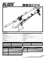 3
3
-
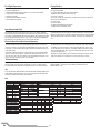 4
4
-
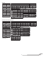 5
5
-
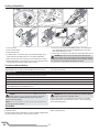 6
6
-
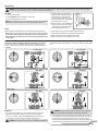 7
7
-
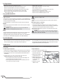 8
8
-
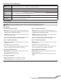 9
9
-
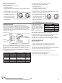 10
10
-
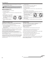 11
11
-
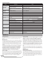 12
12
-
 13
13
-
 14
14
-
 15
15
-
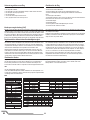 16
16
-
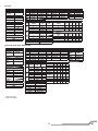 17
17
-
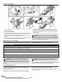 18
18
-
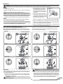 19
19
-
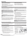 20
20
-
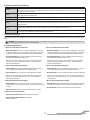 21
21
-
 22
22
-
 23
23
-
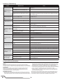 24
24
-
 25
25
-
 26
26
-
 27
27
-
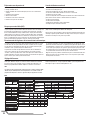 28
28
-
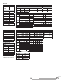 29
29
-
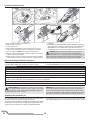 30
30
-
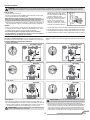 31
31
-
 32
32
-
 33
33
-
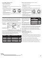 34
34
-
 35
35
-
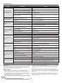 36
36
-
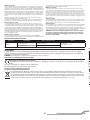 37
37
-
 38
38
-
 39
39
-
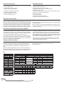 40
40
-
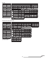 41
41
-
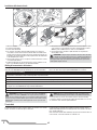 42
42
-
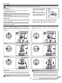 43
43
-
 44
44
-
 45
45
-
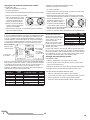 46
46
-
 47
47
-
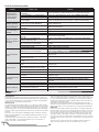 48
48
-
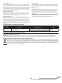 49
49
-
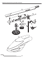 50
50
-
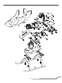 51
51
-
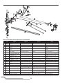 52
52
-
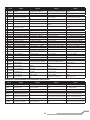 53
53
-
 54
54


Blade 360 CFX 3S Manuale utente
- Categoria
- Giocattoli telecomandati
- Tipo
- Manuale utente
in altre lingue
- English: Blade 360 CFX 3S User manual
- français: Blade 360 CFX 3S Manuel utilisateur
- Deutsch: Blade 360 CFX 3S Benutzerhandbuch
Documenti correlati
-
Blade BLH9319 Manuale del proprietario
-
-
-
-
Blade BLH5450 Manuale del proprietario
-
Blade AR7200BX 7-Ch DSMX Flybarless Control System Manuale utente
-
-
BNF mCP X BL BNF Manuale utente
-
 RTF Blade CX4 Manuale utente
-

Altri documenti
-
Spektrum Lap Timing System - IR sensor for FCF400 Manuale utente
-
Spektrum SPM66101C Manuale utente
-
E-flite Blade SR Manuale utente
-
E-flite EFL01150 Manuale del proprietario
-
Carrera 501032 Manuale utente
-
Carrera RC Micro Helicopter Istruzioni per l'uso
-
Spektrum SPM6755 Manuale del proprietario
-
-
-
Spektrum DX8 G2 System Manuale del proprietario