Nikon PROSTAFF 7 Riflescope Manuale utente
- Tipo
- Manuale utente

En
Es
Fr
De
It
Se
Nl
Ru
Pb
Pl
Fi
No
Dk
Cz
Ro
Hu
2.5-10×42 2.5-10×50 3-12×42 SF
4-16×42 SF 4-16×50 SF 5-20×50 SF
Manufacturer:
Printed in China (823C)1E/1502
Instruction manual/Manual de instrucciones/Mode d'emploi/Bedienungsanleitung/Manuale di istruzioni/Bruksanvisning/
Handleiding/Инструкция по эксплуатации/Manual de instruções/Instrukcja obsługi/Käyttöopas/Brukerveiledning/
Instruktionsvejledning/Příručka uživatele/Manual de instrucţiuni/Használati utasítás

2
En
3
En
Congratulations on your choice of a Nikon PROSTAFF 7 Riflescope. Your new scope is the finest example of Nikon's rugged and durable construction and precision bright optics; important qualities for a serious shooter's
riflescope.
Whether you use your scope for hunting or for target shooting, the procedure for mounting is identical. A set of high-quality steel mounting rings which have a standard diameter of 30mm(1.2in) are required to mount
the scope. Follow the ring manufacturer's instructions for mounting procedures. After mounting the scope on your rifle, follow the procedures for reticle alignment.
SUPPLIED ITEM(S)
Body ················································1 piece Sunshade (4-16×42 SF, 4-16×50 SF, 5-20×50 SF only) ·······1 piece
Eyepiece cap ············
Objective cap···········
······················· 1 pair
IMPORTANT INFORMATION
IT IS IMPORTANT THAT YOUR NIKON RIFLESCOPE IS MOUNTED PROPERLY AND THAT CAREFUL CONSIDERATION BE GIVEN WHEN MOUNTING YOUR NIKON RIFLESCOPE ON A FIREARM.
WE HIGHLY RECOMMEND THAT YOUR NIKON RIFLESCOPE BE MOUNTED ON YOUR FIREARM BY AN EXPERIENCED, REPUTABLE GUNSMITH.
THE USER ASSUMES ALL RESPONSIBILITY AND LIABILITY FOR HAVING THE NIKON RIFLESCOPE PROPERLY MOUNTED TO A FIREARM AND USING THE NIKON RIFLESCOPE PROPERLY.
ALWAYS CHECK THE CONDITION OF YOUR MOUNTING SYSTEM PRIOR TO USING YOUR FIREARM.
When setting the reticle for hunting, you should determine your standard range and then adjust the reticle based upon that target distance. For targets which vary from that standard distance, according to personal
preference, you may simply adjust the position of the reticle in relation to your target, or you may wish to use the procedure for trajectory compensation.
We hope that you will enjoy your new Nikon Riflescope for many years to come. Enjoy using it, and above all, always follow safe shooting procedures.
N.B. Export of the products* in this manual may be controlled under the laws and relatives of the exporting country. Appropriate export procedure, such as obtaining of export license, shall be required in case of export.
*Products: Hardware and its technical information (including software)
Caution
(1) Do NOT look at the sun through the riflescope. It will permanently damage your eye. This precaution applies to all optical devices, such as cameras and binoculars.
(2) The riflescope is effectively sealed against moisture and dust. You may use your scope safely either in the rain or in dusty climates. To preserve the appearance of the scope, we recommend that it be dried and
cleaned prior to storage. Use a soft cloth for cleaning metal surfaces and use photographic lens tissue to clean the scope's lenses.

4
En
5
En
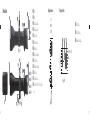
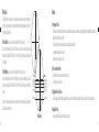
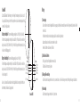
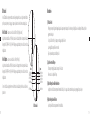
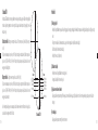
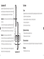
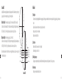
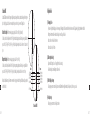
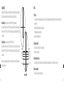
1. Nomenclature
Fig. 1-1
2.5-10×42
2.5-10×50
Fig. 1-2
3-12×42 SF
4-16×42 SF
4-16×50 SF
5-20×50 SF
1 Objective lens
2 Eyepiece lens
3 Elevation adjustment turret
4 Windage adjustment turret
5 Eyepiece adjustment
6 Power index dot
7 Power scale
8 Power selector ring
9 Diopter index dot
0 Side focus adjustment turret
a Distance scale
b Distance index
c Sunshade
(4-16×42 SF, 4-16×50 SF and 5-20×50 SF only)
Fig. 1-4
Shipped attached to
riflescope
1 Adjustment turret
2 Screw for adjustment turret
3 Cap for adjustment turret
Shipped
attached to
riflescope
Fig. 1-3
Elevation adjustment Windage adjustment

6
En
7
En
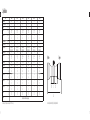
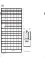
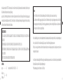
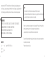
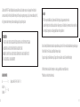
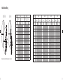
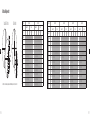
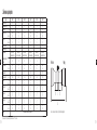
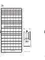
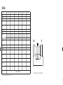
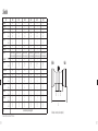
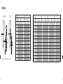
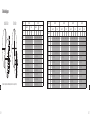
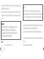
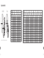
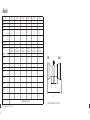
2. Specifications
Model 2.5-10×42 2.5-10×50 3-12×42 SF 4-16×42 SF 4-16×50 SF 5-20×50 SF
Actual magnification (×) 2.5-10 2.5-10 3-12 4-16 4-16 5-20
Effective objective diameter (mm) 42 50 42 42 50 50
Exit pupil * (mm) 4.2 5 3.5 2.6 3.1 2.5
Eye relief ** (mm)
(in)
101.6-94.0
4.0-3.7
101.6-94.0
4.0-3.7
101.6-91.4
4.0-3.6
101.6-91.4
4.0-3.6
101.6-91.4
4.0-3.6
101.6-91.4
4.0-3.6
Tube diameter (mm)
(in)
30
1.2
30
1.2
30
1.2
30
1.2
30
1.2
30
1.2
Objective outside diameter (mm) 52.3 60.3 52.3 52.3 60.3 60.3
Eyepiece outside diameter (mm) 44 44 44 44 44 44
Adjustment graduation 1 click: 7 mm @ 100 m
1 click: 1/4 in @ 100 yd.
1 click: 7 mm @ 100 m
1 click: 1/4 in @ 100 yd.
1 click: 7 mm @ 100 m
1 click: 1/4 in @ 100 yd.
1 click: 7 mm @ 100 m
1 click: 1/4 in @ 100 yd.
1 click: 7 mm @ 100 m
1 click: 1/4 in @ 100 yd.
1 click: 7 mm @ 100 m
1 click: 1/4 in @ 100 yd.
Max. internal adjustment ***(MOA) 140 140 120 90 90 70
Parallax setting (m)
(yd.)
91.44
100
91.44
100
45.72-∞
50-∞
45.72-∞
50-∞
45.72-∞
50-∞
45.72-∞
50-∞
Field of view at 100m ** (m)
14.5-3.6 14.5-3.6 12.1-3.0 9.1-2.3 9.1-2.3 7.3-1.8
Field of view at 100yd ** (ft) 43.6-10.9 43.6-10.9 36.4-9.1 27.2-6.8 27.2-6.8 21.8-5.5
Length (a) (mm)
(in)
320
12.6
348
13.7
335
13.2
345
13.6
375
14.8
380
15.0
Mount length (b) (mm)
(in)
56
2.2
57
2.2
60
2.4
71
2.8
84
3.3
84
3.3
Mount length (c) (mm)
(in)
32
1.3
32
1.3
32
1.3
32
1.3
32
1.3
32
1.3
Mount length (d) (mm)
(in)
53
2.1
53
2.1
53
2.1
53
2.1
53
2.1
53
2.1
W
eight (g)
(oz)
520
18.3
575
20.3
550
19.4
550
19.4
625
22.0
610
21.5
Structure
Waterproof (up to 1 meter for 10 minutes) and nitrogen gas purged
*at maximum magnification **(at minimum magnification)-(at maximum magnification) ***MOA = Minute of Angle
Objective Eyepiece
Letters a to d in the diagram above refer to lengths (a) to (d) shown in the Specifications table.

8
En
9
En
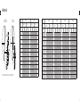
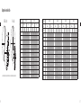
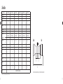
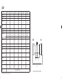
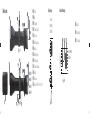
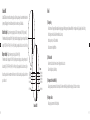
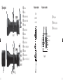
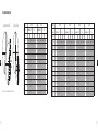
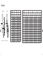
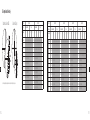
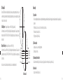
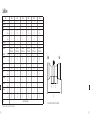
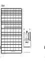
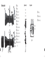
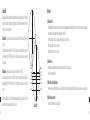
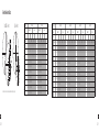
Standard BDC reticle
Duplex Reticle
Model 2.5-10×42 2.5-10×50
Reticle Standard BDC Duplex Standard BDC Duplex
Magni cation (×) 2.5 10 2.5 10 2.5 10 2.5 10
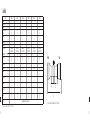
Reticle subtensions (cm at 100 metres/inches at 100yards)
Unit (cm) (in) (cm) (in) (cm) (in) (cm) (in) (cm) (in) (cm) (in) (cm) (in) (cm) (in)
A 2.78 1.00 0.70 0.25 8.45 3.04 2.11 0.76 2.78 1.00 0.70 0.25 8.45 3.04 2.11 0.76
B 77.84 28.00 19.46 7.00 2.22 0.80 0.56 0.20 77.84 28.00 19.46 7.00 2.22 0.80 0.56 0.20
C 16.68 6.00 4.17 1.50 77.17 27.76 19.29 6.94 16.68 6.00 4.17 1.50 77.17 27.76 19.29 6.94
D 22.24 8.00 5.56 2.00 22.24 8.00 5.56 2.00
E 22.24 8.00 5.56 2.00 22.24 8.00 5.56 2.00
F 50.04 18.00 12.51 4.50 50.04 18.00 12.51 4.50
G 77.84 28.00 19.46 7.00 77.84 28.00 19.46 7.00
H 122.32 44.00 30.58 11.00 122.32 44.00 30.58 11.00
I 166.80 60.00 41.70 15.00 166.80 60.00 41.70 15.00
J 11.12 4.00 2.78 1.00 11.12 4.00 2.78 1.00
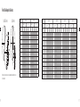
Model 3-12×42 SF 4-16×42 SF 4-16×50 SF 5-20×50 SF
Reticle Standard BDC Duplex Standard BDC Duplex Standard BDC Duplex Standard BDC Duplex
Magni cation (×) 3 12 3 12 4 16 4 16 4 16 4 16 5 20 5 20
Reticle subtensions (cm at 100 metres/inches at 100yards)
Unit (cm) (in) (cm) (in) (cm) (in) (cm) (in) (cm) (in) (cm) (in) (cm) (in) (cm) (in) (cm) (in) (cm) (in) (cm) (in) (cm) (in) (cm) (in) (cm) (in) (cm) (in) (cm)(in)
A 2.78 1.00 0.70 0.25 7.01 2.52 1.75 0.63 2.78 1.00 0.70 0.25 5.26 1.89 1.31 0.47 2.78 1.00 0.70 0.25 5.23 1.88 1.31 0.47 2.78 1.00 0.70 0.25 4.23 1.52 1.06 0.38
B 66.72 24.00 16.68 6.00 1.78 0.64 0.44 0.16 44.48 16.00 11.12 4.00 1.33 0.48 0.33 0.12 44.48 16.00 11.12 4.00 1.33 0.48 0.33 0.12 44.48 16.00 11.12 4.00 1.11 0.40 0.28 0.10
C 16.68 6.00 4.17 1.50 64.38 23.16 16.10 5.79 16.68 6.00 4.17 1.50 47.93 17.24 11.98 4.31 16.68 6.00 4.17 1.50 47.93 17.24 11.98 4.31 16.68 6.00 4.17 1.50 38.92 14.00 9.73 3.50
D 22.24 8.00 5.56 2.00 22.24 8.00 5.56 2.00 22.24 8.00 5.56 2.00 22.24 8.00 5.56 2.00
E 22.24 8.00 5.56 2.00 22.24 8.00 5.56 2.00 22.24 8.00 5.56 2.00 22.24 8.00 5.56 2.00
F 50.04 18.00 12.51 4.50 50.04 18.00 12.51 4.50 50.04 18.00 12.51 4.50 50.04 18.00 12.51 4.50
G 77.84 28.00 19.46 7.00 77.84 28.00 19.46 7.00 77.84 28.00 19.46 7.00 77.84 28.00 19.46 7.00
H 122.32 44.00 30.58 11.00 122.32 44.00 30.58 11.00 122.32 44.00 30.58 11.00 122.32 44.00 30.58 11.00
I 166.80 60.00 41.70 15.00 166.80 60.00 41.70 15.00 166.80 60.00 41.70 15.00 166.80 60.00 41.70 15.00
J 11.12 4.00 2.78 1.00 11.12 4.00 2.78 1.00 11.12 4.00 2.78 1.00 11.12 4.00 2.78 1.00
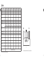
Reticle Subtension Chart
Letters A to J in the diagram above refer to the reticle subtensions of units A to J shown on the table to the right.

10
En
11
En
(3) Adjustment of the riflescope
Sighting through the riflescope, align the rifle with your aiming point on the target and shoot a trial round. If the bullet does not hit the aiming point, adjust the elevation and windage as follows:
If the bullet hits under the aiming point, turn the elevation adjustment turret (counter-clockwise) in the direction of the a rrow marked “U” for up. If the bullet hits high, turn the elevation adjustment turret (clock-
wise) in the direction of the arrow marked “D” for down.
If the bullet hits to the right of the aiming point, turn the windage adjustment turret (clockwise) in the direction of the arrow marked “L” for left. If the bullet hits to the left of the aiming point, turn the windage
adjustment turret (counter-clockwise) in the direction of the arrow marked “R” for right.
After the reticle has been adjusted to the point of impact, replace the turret cap for both the windage and elevation adjustm ent turrets.
3. Instructions
(1) Focusing
1 Look through the eyepiece with your eye positioned about 10 cm (4 in) away from the eyepiece to see the reticle you have purchased. Be sure your eye is positioned with proper alignment and with proper eye
relief, otherwise the view will “black out.”
2 Point the objective end of the scope at the sky (NOT point it at the sun) or at a plain unpatterned wall.
3 Turn the eyepiece adjustment counter-clockwise and then turn it clockwise until the reticle appears sharp.
(2) Magnification
The PROSTAFF 7 Riflescope has variable magnification. For details, see “2. Specifications”.
To change powers, rotate the power selector ring until the desired magnification appears adjacent to the power index dot.

12
En
13
En
(4) Zero setting of adjustment turret
The elevation adjustment and windage adjustment turrets have a retracting system. After the reticle has been adjusted to match the point of impact, pull up the elevation adjustment or windage adjustment turret
to disengage. The turret can now be turned freely. Align the zero number to the index line to set the zero setting, and then release the turret. The turret automatically retracts to the original position.
(5) Adjustable side focus
The PROSTAFF 7 Riflescope 3-12×42 SF, 4-16×42 SF, 4-16×50 SF, 5-20×50 SF can be more precisely focused within the range of at least 45.72 m (50 yd.) to infinity by rotating the side focus adjustment.
Parallax can be eliminated and sight alignment will be accurate.
Use its distance scale as a reference guide.
Note:
The windage and elevation scales of the PROSTAFF 7 Riflescopes are calibrated in divisions of 1/4 minute of angle with a clic k at intervals of 1/4 minute of angle (1 division).
When adjusting the reticle to the point of aim, remember that 1 minute of angle equals approximately 2.54 cm (1 in) at 91.44 m (100 yd.).
Therefore, if the impact point is 5.08 cm (2 in) low and 2.54 cm (1 in) right at 91.44 m (100 yd.) Parallax Setting, you should adjust 2 minutes of angle up and 1 minute of angle left.
In the case of 45.72 m (50 yd.) Parallax Setting, the adjusting value is 2×. In the case of 68.58 m (75 yd.) Parallax Setting, the adjusting value is 1.5×.
Utilizing the BDC reticle
Thank you for choosing the Nikon BDC reticle ri escope. The BDC reticle is designed to compensate for the trajectory of your rearm. Regardless of the particular style of BDC reticle you have, the position of the circles are
based upon an average trajectory for some of the more popular projectiles and cartridges on the market based upon the intended use of the scope itself.
Please note that the reticle is based upon ballistic information and may or may not meet the same results for you as there are many variables that come into play such as:
Actual Velocity (Ammunition manufactures’ information in regards to muzzle velocity may or may not match the velocity your rearm produces. The best way to determine the actual muzzle velocity for your rearm
is to use a chronograph).
Temperature
Humidity
Altitude
Barometric Pressure
Condition and inherent accuracy of the rearm
The mounting system and how true it positions the scope to the centerline of the bore

14
En
15
En
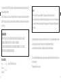
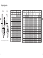
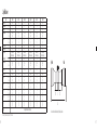
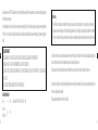
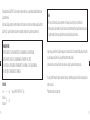
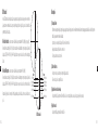
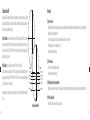
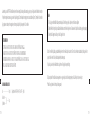
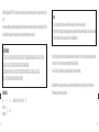
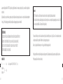
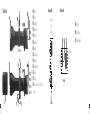
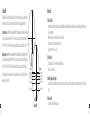
Standard BDC
The standard BDC reticle is designed for use with either of the following cartridge categories. Please note that we highly recommend
polymer tipped bullets for long range shooting as they are more aero-dynamic and tend to provide a atter trajectory.
Standard Velocity – Cartridges with a muzzle velocity of approximately 853 m/s (2800 fps (feet per second)).
We recommend that you zero the rearm at 91 m (100 yd.) with standard velocity cartridges, this would provide bullet drop compensation
for 183, 274, 366 and 457 m (200, 300, 400 and 500 yd.) using the respective ballistic circles as shown in the gure to the right.
Magnum Velocity – Cartridges with a muzzle velocity of approximately 914 m/s (3000 fps).
We recommend that you zero the rearm at 183 m (200 yd.) with magnum velocity cartridges, this would provide bullet drop compensa-
tion for 274, 366, 457 and 549 m (300, 400, 500 and 600 yd.) using the respective ballistic circles as shown right.
Please note that your rearm may or may not match the information listed for bullet drop based upon the variables listed in this section.
Standard
183 m /200 yd.
Magnum
274 m /300 yd
366 m /400 yd.
457 m /500 yd.
549 m /600 yd.
91 m /100 yd.
183 m /200 yd.
274 m /300 yd
366 m /400 yd.
457 m /500 yd.
Standard BDC
Maintenance
(1) Lens cleaning
To remove dirt or fingerprints, soak gauze or lens cleaning paper (silicon-free paper sold at camera retailers) with a small quantity of absolute alcohol (available from drugstores) and lightly wipe off the affected areas.
Wiping with a handkerchief or leather may damage the lens surface and is not recommended.
Dust may scratch the lens surface or corrode the lens.
Brush dust off using a soft oil-free brush.
(2) Scope exterior
Use a soft dry cloth to wipe off any dirt or fingerprints that might accumulate.
It is not necessary to oil the scope's surface.
(3) Windage/elevation adjustments
These adjustments are permanently lubricated. Do not attempt to lubricate them. Cover them with the caps supplied, except when adjusting them, to keep out dust and dirt.
(4) Eyepiece adjustment
This adjustment is permanently lubricated. Do not attempt to lubricate it.

16
En
17
En
(5) Power selector ring
No lubrication is required for the power selector ring.
Do not pull up or remove the rubber covering on the power selector ring.
Waterproof models:
The riflescope is waterproof, and will suffer no damage to the optical system if submerged or dropped in water to a maximum depth of 1 m (3 ft 3 in) for up to 10 minutes.
The riflescope offers the following advantages:
Can be used in conditions of high humidity, dust and rain without risk of damage.
Nitrogen-filled design makes it resistant to condensation and mold.
Observe the following precautions when using the riflescope:
The riflescope should not be operated nor held in running water.
Any moisture should be wiped off before adjusting movable parts (adjustment turret, eyepiece, etc.) of the riflescope to prevent damage and for safety reasons.
To keep your riflescope in optimal condition, Nikon Vision recommends regular servicing by an authorized dealer.
Specifications and equipment are subject to change without any notice or obligation on the part of the manufacturer

18
Es
19
Es
Le felicitamos por elegir una mira telescópica Nikon PROSTAFF 7. Esta nueva mira telescópica es el mejor ejemplo de un producto Nikon compacto y duradero fabricado con una óptica brillante de precisión; cualidades
importantes para la mira telescópica de un rifle profesional.
Tanto si utiliza la mira telescópica para la caza como si la utiliza para el tiro al blanco, el procedimiento de montaje es idéntico. Se necesita un conjunto de anillos de montaje de acero de alta calidad con un diámetro
estándar de 30 mm (1,2 pulg.) para montar la mira telescópica. Siga las instrucciones del fabricante del anillo para los procedimientos de montaje. Una vez montada la mira telescópica en el rifle, siga los procedimientos
de alineación de la retícula.
ARTÍCULO(S) SUMINISTRADO(S)
Cuerpo ·············································1 pieza Sombrilla (solo 4-16×42 SF, 4-16×50 SF y 5-20×50 SF) ·····1 pieza
Tapa del ocular ········
Tapa del objetivo ·····
······················· 1 par
INFORMACIÓN IMPORTANTE
ES IMPORTANTE QUE LA MIRA TELESCÓPICA NIKON SE MONTE CORRECTAMENTE Y QUE EL MONTAJE DE LA MIRA TELESCÓPICA NIKON EN UN ARMA DE FUEGO SE HAGA CON CUIDADO.
RECOMENDAMOS QUE SEA UN ARMERO CON EXPERIENCIA Y REPUTACIÓN EL QUE MONTE LA MIRA TELESCÓPICA EN EL ARMA DE FUEGO.
EL USUARIO ASUME TODA LA RESPONSABILIDAD POR TENER LA MIRA TELESCÓPICA NIKON MONTADA CORRECTAMENTE EN UN ARMA DE FUEGO Y POR EL USO CORRECTO DE LA MIRA.
SIEMPRE VERIFICAR EL ESTADO DE SU SISTEMA DE MONTAJE ANTES DE USAR SU ARMA DE FUEGO.
Al configurar la retícula para cazar, debe especificar el alcance estándar y, a continuación, ajustar la retícula en función de la distancia al blanco. En el caso de blancos que pueden variar desde esa distancia estándar, y de
acuerdo con las preferencias personales, basta con ajustar la posición de la retícula en relación con el blanco, o utilizar el procedimiento de compensación de la trayectoria.
Esperamos que disfrute de su nueva mira telescópica Nikon durante muchos años. Disfrute utilizándola, y sobre todo, siga siempre los procedimientos de disparo seguro.
N.B. La exportación de los productos* de este manual puede estar controlada por las leyes y regulaciones del país exportador. Se requerirá un procedimiento de exportación adecuado, como la obtención de la licencia de
exportación, en caso de exportación.
*Productos: hardware e información técnica (incluido el software)
Precaución
(1) NO mire al sol a través de la mira telescópica. Le causaría daños irreparables en los ojos. Esta precaución se aplica a todos los dispositivos ópticos, como cámaras y binoculares.
(2) La mira telescópica está totalmente sellada contra el polvo y la humedad. Puede utilizar la mira telescópica de forma segura, ya sea en climas lluviosos o con mucho polvo. Con el fin de mantener la mira telescó-
pica en buenas condiciones, le sugerimos que la seque y limpie antes de guardarla. Utilice un paño suave para limpiar las superficies metálicas y una gamuza para lentes fotográficas para limpiar los objetivos
de la mira telescópica.

20
Es
21
Es
1. Nomenclatura
Fig. 1-1
2.5-10×42
2.5-10×50
Fig. 1-2
3-12×42 SF
4-16×42 SF
4-16×50 SF
5-20×50 SF
1 Lente del objetivo
2 Lente del ocular
3 Torreta de ajuste de elevación
4 Torreta de ajuste de efecto del viento
5 Ajuste del ocular
6 Punto de índice de potencia
7 Escala de potencia
8 Anillo del selector de potencia
9 Punto de índice dióptrico
0 Torreta de ajuste de enfoque lateral
a Escala de distancia
b Índice de distancia
c Sombrilla
(solo 4-16×42 SF, 4-16×50 SF y 5-20×50 SF)
Fig. 1-4
Se entrega junto con
la mira telescópica
1 Torreta de ajuste
2 Tornillo para torreta de ajuste
3 Tapa para torreta de ajuste
Se entrega
junto con la mira
telescópica
Fig. 1-3
Ajuste de elevación Ajuste de efecto del viento

22
Es
23
Es
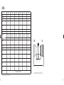
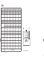
2. Especificaciones
Modelo 2.5-10×42 2.5-10×50 3-12×42 SF 4-16×42 SF 4-16×50 SF 5-20×50 SF
Ampliación real (×) 2,5-10 2,5-10 3-12 4-16 4-16 5-20
Diámetro real del objetivo (mm) 42 50 42 42 50 50
Pupila de salida* (mm) 4,2 5 3,5 2,6 3,1 2,5
Distancia entre el ojo y el ocular** (mm)
(pulg.)
101,6-94,0
4,0-3,7
101,6-94,0
4,0-3,7
101,6-91,4
4,0-3,6
101,6-91,4
4,0-3,6
101,6-91,4
4,0-3,6
101,6-91,4
4,0-3,6
Diámetro del tubo (mm)
(pulg.)
30
1,2
30
1,2
30
1,2
30
1,2
30
1,2
30
1,2
Diámetro exterior del objetivo (mm) 52,3 60,3 52,3 52,3 60,3 60,3
Diámetro exterior del ocular (mm) 44 44 44 44 44 44
Graduación del ajuste 1 clic: 7 mm @ 100 metros
1 clic: 1/4 pulg. @ 100 yardas
1 clic: 7 mm @ 100 metros
1 clic: 1/4 pulg. @ 100 yardas
1 clic: 7 mm @ 100 metros
1 clic: 1/4 pulg. @ 100 yardas
1 clic: 7 mm @ 100 metros
1 clic: 1/4 pulg. @ 100 yardas
1 clic: 7 mm @ 100 metros
1 clic: 1/4 pulg. @ 100 yardas
1 clic: 7 mm @ 100 metros
1 clic: 1/4 pulg. @ 100 yardas
Ajuste interno máximo ***(MOA) 140 140 120 90 90 70
Ajuste de paralaje (metros)
(yardas)
91,44
100
91,44
100
45,72-∞
50-∞
45,72-∞
50-∞
45,72-∞
50-∞
45,72-∞
50-∞
Campo de visión a una distancia de 100 metros ** (metros)
14,5-3,6 14,5-3,6 12,1-3,0 9,1-2,3 9,1-2,3 7,3-1,8
Campo de visión a una distancia de 100 yardas ** (pies) 43,6-10,9 43,6-10,9 36,4-9,1 27,2-6,8 27,2-6,8 21,8-5,5
Longitud (a) (mm)
(pulg.)
320
12,6
348
13,7
335
13,2
345
13,6
375
14,8
380
15,0
Longitud de montaje (b) (mm)
(pulg.)
56
2,2
57
2,2
60
2,4
71
2,8
84
3,3
84
3,3
Longitud de montaje (c) (mm)
(pulg.)
32
1,3
32
1,3
32
1,3
32
1,3
32
1,3
32
1,3
Longitud de montaje (d) (mm)
(pulg.)
53
2,1
53
2,1
53
2,1
53
2,1
53
2,1
53
2,1
P
eso (gramos)
(onzas)
520
18,3
575
20,3
550
19,4
550
19,4
625
22,0
610
21,5
Estructura A prueba de agua (hasta 1 metro durante 10 minutos) y purgado con gas nitrógeno
*con una ampliación máxima **(con una ampliación mínima)-(con una ampliación máxima) ***MOA = Minuto de ángulo
Objetivo Ocular
Las letras comprendidas entre la a y la d del diagrama anterior hacen referencia a las longitudes de la (a) a la (d) que aparecen en la tabla Especificaciones.

24
Es
25
Es
Retícula BDC estándar
Retícula dúplex
Modelo 2.5-10×42 2.5-10×50
Retícula BDC estándar Dúplex BDC estándar Dúplex
Ampliación (×) 2,5 10 2,5 10 2,5 10 2,5 10
Subtensiones de la retícula (cm a 100 metros/pulgadas a 100 yardas)
Unidad (cm) (pulg.) (cm) (pulg.) (cm) (pulg.) (cm) (pulg.) (cm) (pulg.) (cm) (pulg.) (cm) (pulg.) (cm) (pulg.)
A 2,78 1,00 0,70 0,25 8,45 3,04 2,11 0,76 2,78 1,00 0,70 0,25 8,45 3,04 2,11 0,76
B 77,84 28,00 19,46 7,00 2,22 0,80 0,56 0,20 77,84 28,00 19,46 7,00 2,22 0,80 0,56 0,20
C 16,68 6,00 4,17 1,50 77,17 27,76 19,29 6,94 16,68 6,00 4,17 1,50 77,17 27,76 19,29 6,94
D 22,24 8,00 5,56 2,00 22,24 8,00 5,56 2,00
E 22,24 8,00 5,56 2,00 22,24 8,00 5,56 2,00
F 50,04 18,00 12,51 4,50 50,04 18,00 12,51 4,50
G 77,84 28,00 19,46 7,00 77,84 28,00 19,46 7,00
H 122,32 44,00 30,58 11,00 122,32 44,00 30,58 11,00
I 166,80 60,00 41,70 15,00 166,80 60,00 41,70 15,00
J 11,12 4,00 2,78 1,00 11,12 4,00 2,78 1,00
Modelo 3-12×42 SF 4-16×42 SF 4-16×50 SF 5-20×50 SF
Retícula BDC estándar Dúplex BDC estándar Dúplex BDC estándar Dúplex BDC estándar Dúplex
Ampliación (×) 3 12 3 12 4 16 4 16 4 16 4 16 5 20 5 20
Subtensiones de la retícula (cm a 100 metros/pulgadas a 100 yardas)
Unidad (cm) (pulg.) (cm) (pulg.) (cm) (pulg.) (cm) (pulg.) (cm) (pulg.) (cm) (pulg.) (cm) (pulg.) (cm) (pulg.) (cm) (pulg.) (cm) (pulg.) (cm) (pulg.) (cm) (pulg.) (cm) (pulg.) (cm) (pulg.) (cm) (pulg.) (cm) (pulg.)
A 2,78 1,00 0,70 0,25 7,01 2,52 1,75 0,63 2,78 1,00 0,70 0,25 5,26 1,89 1,31 0,47 2,78 1,00 0,70 0,25 5,23 1,88 1,31 0,47 2,78 1,00 0,70 0,25 4,23 1,52 1,06 0,38
B 66,72 24,00 16,68 6,00 1,78 0,64 0,44 0,16 44,48 16,00 11,12 4,00 1,33 0,48 0,33 0,12 44,48 16,00 11,12 4,00 1,33 0,48 0,33 0,12 44,48 16,00 11,12 4,00 1,11 0,40 0,28 0,10
C 16,68 6,00 4,17 1,50 64,38 23,16 16,10 5,79 16,68 6,00 4,17 1,50 47,93 17,24 11,98 4,31 16,68 6,00 4,17 1,50 47,93 17,24 11,98 4,31 16,68 6,00 4,17 1,50 38,92 14,00 9,73 3,50
D 22,24 8,00 5,56 2,00 22,24 8,00 5,56 2,00 22,24 8,00 5,56 2,00 22,24 8,00 5,56 2,00
E 22,24 8,00 5,56 2,00 22,24 8,00 5,56 2,00 22,24 8,00 5,56 2,00 22,24 8,00 5,56 2,00
F 50,04 18,00 12,51 4,50 50,04 18,00 12,51 4,50 50,04 18,00 12,51 4,50 50,04 18,00 12,51 4,50
G 77,84 28,00 19,46 7,00 77,84 28,00 19,46 7,00 77,84 28,00 19,46 7,00 77,84 28,00 19,46 7,00
H 122,32 44,00 30,58 11,00 122,32 44,00 30,58 11,00 122,32 44,00 30,58 11,00 122,32 44,00 30,58 11,00
I 166,80 60,00 41,70 15,00 166,80 60,00 41,70 15,00 166,80 60,00 41,70 15,00 166,80 60,00 41,70 15,00
J 11,12 4,00 2,78 1,00 11,12 4,00 2,78 1,00 11,12 4,00 2,78 1,00 11,12 4,00 2,78 1,00
Grá co de subtensión de la retícula
Las letras comprendidas entre la A y la J del diagrama anterior hacen referencia a las subtensiones de la retícula de las unidades compren-
didas entre la A y la J que aparecen en la tabla de la derecha.

26
Es
27
Es
(3) Ajuste de la mira telescópica
Mirando por la mira telescópica, alinee el rifle con el punto de mira del blanco y dispare una serie de prueba. Si la bala no alcanza el punto de mira, ajuste la elevación y el efecto del viento del siguiente modo:
Si la bala impacta debajo del punto de mira, gire la torreta de ajuste de elevación (en sentido contrario a las agujas del re loj) en la dirección de la flecha marcada con una “U”, que significa arriba. Si la bala impacta
encima del punto de mira, gire la torreta de ajuste de elevación (en el sentido de las agujas del reloj) en la dirección de la flecha marcada con una “D”, que significa abajo.
Si la bala impacta a la derecha del punto de mira, gire la torreta de ajuste de efecto del viento (en el sentido de las agujas del reloj) en la dirección de la flecha marcada con una “L”, que significa izquierda. Si la bala
impacta a la izquierda del punto de mira, gire la torreta de ajuste de efecto del viento (en sentido contrario a las agujas del reloj) en la dirección de la flecha marcada con una “R”, que significa derecha.
Una vez ajustada la retícula al punto de impacto, vuelva a colocar la tapa de la torreta tanto para la torreta de ajuste de e levación como para la torreta de ajuste de efecto del viento.
3. Instrucciones
(1) Enfoque
1 Mire a través del ocular colocando el ojo a unos 10 cm (4 pulg.) de distancia del ocular para ver la retícula que ha adquirido. Asegúrese de colocar el ojo con la alineación y distancia entre el ojo y el ocular correc-
tos; de lo contrario, “no verá nada”.
2 Apunte el extremo de la mira telescópica al cielo (NO apunte al sol) o a una pared lisa y sin dibujos.
3 Gire el ajuste del ocular en sentido contrario a las agujas del reloj y, a continuación, gírelo en el sentido de las agujas del reloj hasta que la retícula aparezca nítida.
(2) Ampliación
La mira telescópica PROSTAFF 7 tiene una ampliación variable. Para obtener información detallada, consulte “2. Especificacion es”.
Para cambiar de potencia, gire el anillo del selector de potencia hasta la ampliación deseada que aparece junto al punto de índice de potencia.

28
Es
29
Es
(4) Ajuste cero de la torreta de ajuste
Las torretas de ajuste de elevación y de ajuste de efecto del viento disponen de un sistema de repliegue. Una vez ajustada la retícula al punto de impacto, tire hacia arriba de la torreta de ajuste de elevación o de
la torreta de ajuste de efecto del viento para liberarla. Ahora ya se puede girar la torreta como se desee. Alinee el número cero a la línea de índice para configurar el ajuste cero y, a continuación, libere la torreta. La
torreta se repliega automáticamente a la posición original.
(5) Enfoque lateral ajustable
Las miras telescópicas PROSTAFF 7 3-12×42 SF, 4-16×42 SF, 4-16×50 SF, 5-20×50 SF se puede enfocar con mayor precisión en un alcance de al menos 45,72 metros (50 yardas) hasta el infinito girando el ajuste
de enfoque lateral.
Se puede eliminar el paralaje para que la alineación de la mira sea precisa.
Utilice la escala de distancia como una guía de referencia.
Nota:
Las escalas de elevación y de efecto del viento de las miras telescópicas PROSTAFF 7 se calibran en divisiones de 1/4 de minu to de ángulo con un clic a intervalos de 1/4 de minuto de ángulo (una división).
Al ajustar la retícula al punto de mira, no olvide que un minuto de ángulo equivale aproximadamente a 2,54 cm (1 pulg.) en 91,44 metros (100 yardas).
Por lo tanto, si el punto de impacto está 5,08 cm (2 pulg.) más bajo y 2,54 cm (1 pulg.) a la derecha en el ajuste de paralaje de 91,44 metros (100 yardas), debería ajustar dos minutos de ángulo hacia arriba y un
minuto de ángulo a la izquierda.
En el caso de un ajuste de paralaje de 45,72 metros (50 yardas), el valor de ajuste será el doble. En el caso de un ajuste de paralaje de 68,58 metros (75 yardas), el valor de ajuste será de 1,5 veces.
Uso de la retícula BDC
Gracias por elegir la mira telescópica de retícula BDC de Nikon. El diseño de la retícula BDC permite compensar la trayectoria del arma de fuego. Independientemente del estilo concreto de retícula BDC que tenga, la posición
de los círculos se basan en una trayectoria media de algunos de los proyectiles y cartuchos más conocidos del mercado conforme al uso previsto de la propia mira telescópica.
Tenga en cuenta que la retícula se basa en información balística; por lo tanto, es posible que pueda o no obtener los mismos resultados, ya que son muchas las variables que entran en juego, como es el caso de:
Velocidad real (la información de los fabricantes de municiones con respecto a la velocidad inicial puede o no coincidir con la velocidad que genera el arma de fuego. La mejor manera de determinar la velocidad
inicial real del arma de fuego es mediante la utilización de un cronógrafo).
Temperatura
Humedad
Altitud
Presión barométrica
Condición y exactitud propia del arma de fuego
El sistema de montaje y con qué exactitud coloca la mira telescópica en la línea central del calibre

30
Es
31
Es
BDC estándar
La retícula BDC estándar ha sido diseñada para ser utilizada con cualquiera de las categorías de cartucho siguientes. Recomendamos
encarecidamente el uso de balas con punta polimérica para disparos de largo alcance dado que son más aerodinámicas y tienden a ofrecer
una trayectoria más uniforme.
Velocidad estándar: cartuchos con una velocidad inicial aproximada de 853 m/s (2800 fps (pies por segundo)).
Recomendamos el restablecimiento del arma de fuego a cero en 91 m (100 yardas) con cartuchos de velocidad estándar. Esto ofrece una
compensación del desnivel de la bala de 183, 274, 366 y 457 m (200, 300, 400 y 500 yardas) utilizando los círculos balísticos respectivos,
como se muestra en la ilustración de la derecha.
Velocidad Magnum: cartuchos con una velocidad inicial aproximada de 914 m/s (3000 fps).
Recomendamos el restablecimiento del arma de fuego a cero en 183 m (200 yardas) con cartuchos de velocidad magnum. Esto ofrece una
compensación del desnivel de la bala de 274, 366, 457 y 549 m (300, 400, 500 y 600 yardas) utilizando los círculos balísticos respectivos,
como se muestra a la derecha.
Tenga en cuenta que el arma de fuego puede o no coincidir con la información que aparece relativa al desnivel de la bala basada en las
variables que se incluyen en esta sección.
Estándar
183 m/200 yardas
Magnum
274 m/300 yardas
366 m/400 yardas
457 m/500 yardas
549 m/600 yardas
91 m/100 yardas
183 m/200 yardas
274 m/300 yardas
366 m/400 yardas
457 m/500 yardas
BDC estándar
Mantenimiento
(1) Limpieza del objetivo
Para eliminar la suciedad o las huellas dactilares, humedezca una gasa o un papel de limpieza de objetivos (papel sin silicio, de venta en las tiendas de fotografía) con una pequeña cantidad de alcohol puro (disponible
en farmacias) y limpie suavemente las áreas afectadas.
No se recomienda la limpieza con un pañuelo ni con una gamuza de cuero, ya que se podría dañar la superficie del objetivo.
El polvo puede rayar la superficie del objetivo o corroerlo.
Limpie el polvo utilizando un cepillo suave que no contenga aceite.
(2) Superficie exterior de la mira telescópica
Utilice un paño suave y seco para limpiar la suciedad o las huellas dactilares que pudieran acumularse.
No es necesario lubricar la superficie de la mira telescópica.
(3) Ajustes de efecto del viento/elevación
Estos ajustes se encuentran permanentemente lubricados. No intente lubricarlos. Cúbralos con las tapas suministradas, salvo al ajustarlos, para protegerlos del polvo y la suciedad.
(4) Ajuste del ocular
Este ajuste se encuentra permanentemente lubricado. No intente lubricarlo.

32
Es
33
Es
(5) Anillo del selector de potencia
El anillo del selector de potencia no requiere ningún tipo de lubricación.
No tire hacia arriba ni extraiga la goma que cubre el anillo del selector de potencia.
Modelos impermeables:
La mira telescópica es impermeable y el sistema óptico no sufrirá ningún daño si se sumerge o si se cae al agua a una profundidad máxima de 1 metro (3 pies y 3 pulgadas) durante un tiempo máximo de 10 minutos.
La mira telescópica ofrece las siguientes ventajas:
Se puede utilizar en condiciones de humedad elevada, polvo y lluvia sin que se produzcan daños.
Diseño relleno con nitrógeno que lo hace resistente a la condensación y al moho.
Tenga en cuenta las siguientes precauciones al utilizar la mira telescópica:
La mira telescópica no se debe utilizar ni colocar debajo del agua corriente.
Antes de ajustar las piezas móviles (torreta de ajuste, ocular, etc.), y por motivos de seguridad, se deberá limpiar cualquier resto de humedad de la mira telescópica para evitar daños.
Para mantener la mira telescópica en excelentes condiciones, Nikon Vision recomienda una revisión periódica por parte de un distribuidor autorizado.
Las especificaciones y el equipo están sujetos a cambios sin previo aviso ni obligación por parte del fabricante

34
Fr
35
Fr
Nous vous félicitons d´avoir choisi une lunette de visée Nikon PROSTAFF 7. Votre nouvelle lunette est un parfait exemple de la robustesse, de la longévité et de la précision des instruments d'optique Nikon -des qualités
importantes pour tout tireur sérieux.
Que vous utilisiez votre lunette pour la chasse ou pour le tir à la cible, la procédure de montage est la même. Un jeu de bagues de montage d'acier de haute qualité d'un diamètre standard de 30mm (1,2pouce) est
nécessaire au montage de la lunette. Pour le montage, suivez les instructions du fabricant des bagues. Après avoir monté la lunette de visée sur votre fusil, réglez l'alignement du réticule (croisée de fils) comme suit.
COLISAGE
Boîtier ··············································1 Pare-soleil (4-16×42 SF, 4-16×50 SF, 5-20×50 SF uniquement) ·········1
Protecteur d’oculaire ······
Capuchon d’objectif ·······
················1paire
INFORMATIONS IMPORTANTES
IL EST IMPORTANT QUE VOTRE LUNETTE DE VISÉE NIKON SOIT CORRECTEMENT MONTÉE ET QUE VOUS SOYEZ PRUDENT LORSQUE VOUS MONTEZ LA LUNETTE DE VISÉE SUR UNE ARME.
NOUS VOUS RECOMMANDONS VIVEMENT DE FAIRE MONTER VOTRE LUNETTE DE VISÉE NIKON SUR VOTRE ARME PAR UN ARMURIER EXPÉRIMENTÉ ET RÉPUTÉ.
L'UTILISATEUR ACCEPTE TOUTE RESPONSABILITÉ CONCERNANT LE MONTAGE DE LA LUNETTE SUR UNE ARME ET CONCERNANT L'UTILISATION DE LA LUNETTE DE VISÉE NIKON.
VÉRIFIEZ TOUJOURS L’ÉTAT DE VOTRE SYSTÈME DE MONTAGE AVANT D’UTILISER VOTRE ARME.
Pour régler le réticule pour la chasse, vous devrez tout d'abord déterminer la portée standard ; réglez ensuite le réticule sur la base de cette distance de cible. Pour des cibles qui débordent de cette distance standard, selon
vos préférences, vous pouvez régler simplement la position du réticule par rapport à la cible, ou bien effectuer une correction de trajectoire.
Nous espérons que votre nouvelle lunette de visée Nikon vous procurera de longues années de satisfaction. Profitez-en, mais avant tout, respectez toujours les consignes de sécurité en matière de tir.
N.B. : l'exportation des produits* objets de ce manuel risque d'être sujette aux lois en vigueur dans le pays exportateur. La mise en œuvre d'un processus d'exportation approprié, comme l'obtention d'une licence d'ex-
portation, peut s'avérer nécessaire.
*Produits : matériel et informations techniques connexes (y compris le logiciel)
Précautions
(1) Ne regardez PAS le soleil par la lunette de visée. Vous vous abîmeriez la vue de façon irrémédiable. Cette précaution s'applique à tous les instruments d'optique, comme les appareils photo et les jumelles.
(2) La lunette de visée est étanche à l'humidité et la poussière. Vous pouvez l'utiliser en toute sécurité sous la pluie et dans les environnements poussiéreux. Pour conserver l'extérieur de la lunette en bon état, nous
vous recommandons de la sécher et de la nettoyer avant de la ranger. Utilisez un chiffon doux pour nettoyer les parties métalliques, et utilisez des papiers pour objectif photo pour nettoyer les lentilles de la lunette.

36
Fr
37
Fr
1. Nomenclature
Fig. 1-1
2.5-10×42
2.5-10×50
Fig. 1-2
3-12×42 SF
4-16×42 SF
4-16×50 SF
5-20×50 SF
1 Objectif
2 Oculaire
3 Tourelle de réglage de hausse
4 Tourelle de réglage de dérive
5 Reglage de l’oculaire
6 Point d’index de puissance
7 Échelle de puissance
8 Bague de sélection de puissance
9 Point-repère de dioptrie
0 Tourelle latérale de mise au point
a Échelle de distance
b Repères gradués de distance
c Pare-soleil
(4-16×42 SF, 4-16×50 SF et 5-20×50 SF unique-
ment)
Fig. 1-4
Livrés montés sur la
lunette
1 Tourelle de réglage
2 Vis de tourelle de réglage
3 Capuchon de tourelle de réglage
Livrés
montés sur
la lunette
Fig. 1-3
Réglage de hausse Réglage de dérive

38
Fr
39
Fr
2. Caractéristiques
Modèle 2.5-10×42 2.5-10×50 3-12×42 SF 4-16×42 SF 4-16×50 SF 5-20×50 SF
Grossissement réel (×) 2,5-10 2,5-10 3-12 4-16 4-16 5-20
Diamètre effectif de l’objectif (mm) 42 50 42 42 50 50
Pupille de sortie* (mm) 4,2 5 3,5 2,6 3,1 2,5
Dégagement oculaire** (mm)
(pouces)
101,6-94,0
4,0-3,7
101,6-94,0
4,0-3,7
101,6-91,4
4,0-3,6
101,6-91,4
4,0-3,6
101,6-91,4
4,0-3,6
101,6-91,4
4,0-3,6
Diamètre de tube (mm)
(pouces)
30
1,2
30
1,2
30
1,2
30
1,2
30
1,2
30
1,2
Diamètre extérieur de l’objectif (mm) 52,3 60,3 52,3 52,3 60,3 60,3
Diamètre extérieur de l’oculaire (mm) 44 44 44 44 44 44
Graduations de réglage 1 clic = 7 mm à 100 m
1 clic = 1/4 pouce à 100 yards
1 clic = 7 mm à 100 m
1 clic = 1/4 pouce à 100 yards
1 clic = 7 mm à 100 m
1 clic = 1/4 pouce à 100 yards
1 clic = 7 mm à 100 m
1 clic = 1/4 pouce à 100 yards
1 clic = 7 mm à 100 m
1 clic = 1/4 pouce à 100 yards
1 clic = 7 mm à 100 m
1 clic = 1/4 pouce à 100 yards
Réglage interne maximal ***(MOA) 140 140 120 90 90 70
Réglage de parallaxe (m)
(yards)
91,44
100
91,44
100
45,72-∞
50-∞
45,72-∞
50-∞
45,72-∞
50-∞
45,72-∞
50-∞
Champ lineaire percu a 100metres** (m) (m)
14,5-3,6 14,5-3,6 12,1-3,0 9,1-2,3 9,1-2,3 7,3-1,8
Champ lineaire percu a 100yards** (pieds) (pieds) 43,6-10,9 43,6-10,9 36,4-9,1 27,2-6,8 27,2-6,8 21,8-5,5
Longueur (a)(mm) (mm)
(pouces)
320
12,6
348
13,7
335
13,2
345
13,6
375
14,8
380
15,0
Longueur de la monture (b)(mm) (mm)
(pouces)
56
2,2
57
2,2
60
2,4
71
2,8
84
3,3
84
3,3
Longueur de la monture (b)(mm) (mm)
(pouces)
32
1,3
32
1,3
32
1,3
32
1,3
32
1,3
32
1,3
Longueur de la monture (d)(mm) (mm)
(pouces)
53
2,1
53
2,1
53
2,1
53
2,1
53
2,1
53
2,1
P
oids (g)
(oz)
520
18,3
575
20,3
550
19,4
550
19,4
625
22,0
610
21,5
Structure Etanche (jusqu’a 1 m et 10 minutes maximum) et purgee a l’azote
*au grossissement maximum ** (au grossissement minimum) - (au grossissement maximum) ***MOA = minute d’angle
Objectif Oculaire
Les lettres a à d du schéma ci-dessus désignent les longueurs (a) à (d) indiquées dans le tableau des caractéristiques.
La pagina si sta caricando...
La pagina si sta caricando...
La pagina si sta caricando...
La pagina si sta caricando...
La pagina si sta caricando...
La pagina si sta caricando...
La pagina si sta caricando...
La pagina si sta caricando...
La pagina si sta caricando...
La pagina si sta caricando...
La pagina si sta caricando...
La pagina si sta caricando...
La pagina si sta caricando...
La pagina si sta caricando...
La pagina si sta caricando...
La pagina si sta caricando...
La pagina si sta caricando...
La pagina si sta caricando...
La pagina si sta caricando...
La pagina si sta caricando...
La pagina si sta caricando...
La pagina si sta caricando...
La pagina si sta caricando...
La pagina si sta caricando...
La pagina si sta caricando...
La pagina si sta caricando...
La pagina si sta caricando...
La pagina si sta caricando...
La pagina si sta caricando...
La pagina si sta caricando...
La pagina si sta caricando...
La pagina si sta caricando...
La pagina si sta caricando...
La pagina si sta caricando...
La pagina si sta caricando...
La pagina si sta caricando...
La pagina si sta caricando...
La pagina si sta caricando...
La pagina si sta caricando...
La pagina si sta caricando...
La pagina si sta caricando...
La pagina si sta caricando...
La pagina si sta caricando...
La pagina si sta caricando...
La pagina si sta caricando...
La pagina si sta caricando...
La pagina si sta caricando...
La pagina si sta caricando...
La pagina si sta caricando...
La pagina si sta caricando...
La pagina si sta caricando...
La pagina si sta caricando...
La pagina si sta caricando...
La pagina si sta caricando...
La pagina si sta caricando...
La pagina si sta caricando...
La pagina si sta caricando...
La pagina si sta caricando...
La pagina si sta caricando...
La pagina si sta caricando...
La pagina si sta caricando...
La pagina si sta caricando...
La pagina si sta caricando...
La pagina si sta caricando...
La pagina si sta caricando...
La pagina si sta caricando...
La pagina si sta caricando...
La pagina si sta caricando...
La pagina si sta caricando...
La pagina si sta caricando...
La pagina si sta caricando...
La pagina si sta caricando...
La pagina si sta caricando...
La pagina si sta caricando...
La pagina si sta caricando...
La pagina si sta caricando...
La pagina si sta caricando...
La pagina si sta caricando...
La pagina si sta caricando...
La pagina si sta caricando...
La pagina si sta caricando...
La pagina si sta caricando...
La pagina si sta caricando...
La pagina si sta caricando...
La pagina si sta caricando...
La pagina si sta caricando...
La pagina si sta caricando...
La pagina si sta caricando...
La pagina si sta caricando...
La pagina si sta caricando...
La pagina si sta caricando...
La pagina si sta caricando...
La pagina si sta caricando...
La pagina si sta caricando...
La pagina si sta caricando...
La pagina si sta caricando...
La pagina si sta caricando...
La pagina si sta caricando...
La pagina si sta caricando...
La pagina si sta caricando...
La pagina si sta caricando...
La pagina si sta caricando...
La pagina si sta caricando...
La pagina si sta caricando...
La pagina si sta caricando...
La pagina si sta caricando...
La pagina si sta caricando...
La pagina si sta caricando...
La pagina si sta caricando...
La pagina si sta caricando...
-
 1
1
-
 2
2
-
 3
3
-
 4
4
-
 5
5
-
 6
6
-
 7
7
-
 8
8
-
 9
9
-
 10
10
-
 11
11
-
 12
12
-
 13
13
-
 14
14
-
 15
15
-
 16
16
-
 17
17
-
 18
18
-
 19
19
-
 20
20
-
 21
21
-
 22
22
-
 23
23
-
 24
24
-
 25
25
-
 26
26
-
 27
27
-
 28
28
-
 29
29
-
 30
30
-
 31
31
-
 32
32
-
 33
33
-
 34
34
-
 35
35
-
 36
36
-
 37
37
-
 38
38
-
 39
39
-
 40
40
-
 41
41
-
 42
42
-
 43
43
-
 44
44
-
 45
45
-
 46
46
-
 47
47
-
 48
48
-
 49
49
-
 50
50
-
 51
51
-
 52
52
-
 53
53
-
 54
54
-
 55
55
-
 56
56
-
 57
57
-
 58
58
-
 59
59
-
 60
60
-
 61
61
-
 62
62
-
 63
63
-
 64
64
-
 65
65
-
 66
66
-
 67
67
-
 68
68
-
 69
69
-
 70
70
-
 71
71
-
 72
72
-
 73
73
-
 74
74
-
 75
75
-
 76
76
-
 77
77
-
 78
78
-
 79
79
-
 80
80
-
 81
81
-
 82
82
-
 83
83
-
 84
84
-
 85
85
-
 86
86
-
 87
87
-
 88
88
-
 89
89
-
 90
90
-
 91
91
-
 92
92
-
 93
93
-
 94
94
-
 95
95
-
 96
96
-
 97
97
-
 98
98
-
 99
99
-
 100
100
-
 101
101
-
 102
102
-
 103
103
-
 104
104
-
 105
105
-
 106
106
-
 107
107
-
 108
108
-
 109
109
-
 110
110
-
 111
111
-
 112
112
-
 113
113
-
 114
114
-
 115
115
-
 116
116
-
 117
117
-
 118
118
-
 119
119
-
 120
120
-
 121
121
-
 122
122
-
 123
123
-
 124
124
-
 125
125
-
 126
126
-
 127
127
-
 128
128
-
 129
129
-
 130
130


Nikon PROSTAFF 7 Riflescope Manuale utente
- Tipo
- Manuale utente
in altre lingue
Documenti correlati
-
Nikon PROSTAFF Riflescope Manuale utente
-
-
-
-
-
-
-
-
