Denon DHT-500SD Operating Instructions Manual
- Categoria
- Lettori DVD
- Tipo
- Operating Instructions Manual

HOME THEATER SYSTEM
DHT-500SD
+
-
+
-
+
-
-
+
-
+
RC-973
A / V
A-B REPEAT
ONOFF
REPEAT RANDOM
CLEAR ZOOM
PROG/DIRECT
MEMO BANDMODE
STATU S
RETURN
ANGLE AUDIO
SUB TITLE
SETUP
TONE/DIMMER
FUNCTIONSURROUNDINPUT MODETEST TONE
DVD
TUNER
CH
321
654
987
0
/
10
ENTER
MUTING
+
10
DISPLAY MENU
TOP MENU
TUNER TV / VCR
NTSC/PAL
SLEEP
TV IN
TUNING /
TV VOL
TV CH TV CH
VCR CH
AV AMPDVD
VCR PWR PWR
TV
PBC
CALL
SURROUND
PARAMETER
CH SELECT
CT RTPTYRDS
TV
DVD TUNER
VIDEO 1 VIDEO 2
RC-973
MASTER VOLUME
PHONES
SURROUND MODE
TONE
FUNCTION
ON/STANDBY
DVD SURROUND
RECEIVER
ADV-500SD
STANDBY
DVD
P.SCAN
D
EX
TITLE CHP
FM MODEMEMORYBAND
TUNING
PROGRESSIVE SCAN
ADV-500SD
SYS-500SD
(SC-A500SD) (SC-C500SD)
(DSW-500SD)
(SC-A500SD)
OPERATING INSTRUCTIONS
BEDIENUNGSANLEITUNG
MODE D’EMPLOI
ISTRUZIONI PER L’USO
INSTRUCCIONES DE OPERACION
GEBRUIKSAANWIJZING
BRUKSANVISNING
FOR ENGLISH READERS PAGE 003 ~ PAGE 035
FÜR DEUTSCHE LESER SEITE 036 ~ SEITE 068
POUR LES LECTEURS FRANCAIS PAGE 069 ~ PAGE 101
PER IL LETTORE ITALIANO PAGINA 102 ~ PAGINA 134
PARA LECTORES DE ESPAÑOL PAGINA 135 ~ PAGINA 167
VOOR NEDERLANDSTALIGE LEZERS PAGINA 168 ~ PAGINA 200
FOR SVENSKA LÄSARE SIDA 201 ~ SIDA 233

2
ENGLISH
NOTE ON USE / HINWEISE ZUM GEBRAUCH /
OBSERVATIONS RELATIVES A L’UTILISATION / NOTE SULL’USO
NOTAS SOBRE EL USO / ALVORENS TE GEBRUIKEN / OBSERVERA
• Avoid high temperatures.
Allow for sufficient heat dispersion when
installed on a rack.
• Vermeiden Sie hohe Temperaturen.
Beachten Sie, daß eine ausreichend
Luftzirkulation gewährleistet wird, wenn
das Gerät auf ein Regal gestellt wird.
• Eviter des températures élevées.
Tenir compte d’une dispersion de chaleur
suffisante lors de l’installation sur une
étagère.
• Evitate di esporre l’unità a temperature
alte.
Assicuratevi che ci sia un’adeguata
dispersione del calore quando installate
l’unità in un mobile per componenti audio.
• Evite altas temperaturas.
Permite la suficiente dispersión del calor
cuando está instalado en la consola.
• Vermijd hoge temperaturen.
Zorg voor een degelijk hitteafvoer indien
het apparaat op een rek wordt geplaatst.
• Undvik höga temperaturer.
Se till att det finns möjlighet till god
värmeavledning vid montering i ett rack.
• Keep the set free from moisture, water,
and dust.
• Halten Sie das Gerät von Feuchtigkeit,
Wasser und Staub fern.
• Protéger l’appareil contre l’humidité,
l’eau et lapoussière.
• Tenete l’unità lontana dall’umidità,
dall’acqua e dalla polvere.
• Mantenga el equipo libre de humedad,
agua y polvo.
• Laat geen vochtigheid, water of stof in
het apparaat binnendringen.
• Utsätt inte apparaten för fukt, vatten och
damm.
• Do not let foreign objects in the set.
• Keine fremden Gegenstände in das
Gerät kommen lassen.
• Ne pas laisser des objets étrangers
dans l’appareil.
• E’ importante che nessun oggetto è
inserito all’interno dell’unità.
• No deje objetos extraños dentro del
equipo.
• Laat geen vreemde voorwerpen in dit
apparaat vallen.
• Se till att främmande föremål inte
tränger in i apparaten.
• Handle the power cord carefully.
Hold the plug when unplugging the cord.
• Gehen Sie vorsichtig mit dem Netzkabel
um.
Halten Sie das Kabel am Stecker, wenn
Sie den Stecker herausziehen.
• Manipuler le cordon d’alimentation avec
précaution.
Tenir la prise lors du débranchement du
cordon.
• Manneggiate il filo di alimentazione con
cura.
Agite per la spina quando scollegate il
cavo dalla presa.
• Maneje el cordón de energía con cuidado.
Sostenga el enchufe cuando desconecte
el cordón de energía.
• Hanteer het netsnoer voorzichtig.
Houd het snoer bij de stekker vast wanneer
deze moet worden aan- of losgekoppeld.
• Hantera nätkabeln varsamt.
Håll i kabeln när den kopplas från el-
uttaget.
• Unplug the power cord when not using
the set for long periods of time.
• Wenn das Gerät eine längere Zeit nicht
verwendet werden soll, trennen Sie das
Netzkabel vom Netzstecker.
• Débrancher le cordon d’alimentation
lorsque l’appareil n’est pas utilisé pendant
de longues périodes.
• Disinnestate il filo di alimentazione quando
avete l’intenzione di non usare il filo di
alimentazione per un lungo periodo di
tempo.
• Desconecte el cordón de energía cuando
no utilice el equipo por mucho tiempo.
• Neem altijd het netsnoer uit het stopkontakt
wanneer het apparaat gedurende een
lange periode niet wordt gebruikt.
• Koppla ur nätkabeln om apparaten inte
kommer att användas i lång tid.
• Do not let insecticides, benzene, and
thinner come in contact with the set.
• Lassen Sie das Gerät nicht mit Insektiziden,
Benzin oder Verdünnungsmitteln in
Berührung kommen.
• Ne pas mettre en contact des insecticides,
du benzène et un diluant avec l’appareil.
• Assicuratevvi che l’unità non venga in
contatto con insetticidi, benzolo o solventi.
• No permita el contacto de insecticidas,
gasolina y diluyentes con el equipo.
• Laat geen insektenverdelgende middelen,
benzine of verfverdunner met dit apparaat
in kontakt komen.
• Se till att inte insektsmedel på spraybruk,
bensen och thinner kommer i kontakt med
apparatens hölje.
• Never disassemble or modify the set in
any way.
• Versuchen Sie niemals das Gerät
auseinander zu nehmen oder auf jegliche
Art zu verändern.
• Ne jamais démonter ou modifier l’appareil
d’une manière ou d’une autre.
• Non smontate mai, nè modificate l’unità
in nessun modo.
• Nunca desarme o modifique el equipo de
ninguna manera.
• Nooit dit apparaat demonteren of op
andere wijze modifiëren.
• Ta inte isär apparaten och försök inte
bygga om den.
• Do not obstruct the ventilation holes.
• Die Belüftungsöffnungen dürfen nicht
verdeckt werden.
• Ne pas obstruer les trous d’aération.
• Non coprite i fori di ventilazione.
• No obstruya los orificios de ventilación.
• De ventilatieopeningen mogen niet
worden beblokkeerd.
• Täpp inte till ventilationsöppningarna.
* (For sets with ventilation holes)
CAUTION
•
The ventilation should not be impeded by covering the ventilation openings with items, such as newspapers, table-cloths,
curtains, etc.
•
No naked flame sources, such as lighted candles, should be placed on the apparatus.
•
Please be care the environmental aspects of battery disposal.
•
The apparatus shall not be exposed to dripping or splashing for use.
•
No objects filled with liquids, such as vases, shall be placed on the apparatus.
CAUTION
RISK OF ELECTRIC SHOCK
DO NOT OPEN
CAUTION: TO REDUCE THE RISK OF
ELECTRIC SHOCK, DO NOT
REMOVE COVER (OR BACK). NO
USER SERVICEABLE PARTS
INSIDE. REFER SERVICING TO
QUALIFIED SERVICE
PERSONNEL.
The lightning flash with arrowhead symbol,
within an equilateral triangle, is intended to
alert the user to the presence of uninsulated
“dangerous voltage” within the product’s
enclosure that may be of sufficient magnitude
to constitute a risk of electric shock to
persons.
The exclamation point within an equilateral
triangle is intended to alert the user to the
presence of important operating and
maintenance (servicing) instructions in the
literature accompanying the appliance.
CLASS 1 LASER PRODUCT
LUOKAN 1 LASERLAITE
KLASS 1 LASERAPPARAT
ADVARSEL: USYNLIG LASERSTRÅLING VED ÅBNING, NÅR
SIKKERHEDSAFBRYDERE ER UDE AF FUNKTION.
UNDGÅ UDSAETTELSE FOR STRÅLING.
VAROITUS! LAITTEEN KÄYTTÄMINEN MUULLA KUIN TÄSSÄ
KÄYTTÖOHJEESSA MAINITULLA TAVALLA SAATTAA
ALTISTAA KÄYTTÄJÄN TURVALLISUUSLUOKAN 1
YLITTÄVÄLLE NÄKYMÄTTÖMÄLLE LASERSÄTEILYLLE.
VARNING- OM APPARATEN ANVÄNDS PÅ ANNAT SÄTT ÄN I DENNA
BRUKSANVISNING SPECIFICERATS, KAN ANVÄNDAREN
UTSÄTTAS FÖR OSYNLIG LASERSTRÅLNING SOM
ÖVERSKRIDER GRÄNSEN FÖR LASERKLASS 1.
,
CLASS 1
LASER
PRODUCT
,
,,
• DECLARATION OF CONFORMITY
We declare under our sole responsibility that this
product, to which this declaration relates, is in
conformity with the following standards:
EN60065, EN55013, EN55020, EN61000-3-2 and
EN61000-3-3.
Following the provisions of 73/23/EEC,
89/336/EEC and 93/68/EEC Directive.
• ÜBEREINSTIMMUNGSERKLÄRUNG
Wir erklären unter unserer Verantwortung, daß
dieses Produkt, auf das sich diese Erklärung
bezieht, den folgenden Standards entspricht:
EN60065, EN55013, EN55020, EN61000-3-2 und
EN61000-3-3.
Entspricht den Verordnungen der Direktive
73/23/EEC, 89/336/EEC und 93/68/EEC.
• DECLARATION DE CONFORMITE
Nous déclarons sous notre seule responsabilité
que l’appareil, auquel se réfère cette déclaration,
est conforme aux standards suivants:
EN60065, EN55013, EN55020, EN61000-3-2 et
EN61000-3-3.
D’après les dispositions de la Directive 73/23/EEC,
89/336/EEC et 93/68/EEC.
• DICHIARAZIONE DI CONFORMITÀ
Dichiariamo con piena responsabilità che questo
prodotto, al quale la nostra dichiarazione si
riferisce, è conforme alle seguenti normative:
EN60065, EN55013, EN55020, EN61000-3-2 e
EN61000-3-3.
In conformità con le condizioni delle direttive
73/23/EEC, 89/336/EEC e 93/68/EEC.
QUESTO PRODOTTO E’ CONFORME
AL D.M. 28/08/95 N. 548
• DECLARACIÓN DE CONFORMIDAD
Declaramos bajo nuestra exclusiva responsabilidad
que este producto al que hace referencia esta
declaración, está conforme con los siguientes
estándares:
EN60065, EN55013, EN55020, EN61000-3-2 y
EN61000-3-3.
Siguiendo las provisiones de las Directivas
73/23/EEC, 89/336/EEC y 93/68/EEC.
• EENVORMIGHEIDSVERKLARING
Wij verklaren uitsluitend op onze
verantwoordelijkheid dat dit produkt, waarop deze
verklaring betrekking heeft, in overeenstemming is
met de volgende normen:
EN60065, EN55013, EN55020, EN61000-3-2 en
EN61000-3-3.
Volgens de bepalingen van de Richtlijnen
73/23/EEC, 89/336/EEC en 93/68/EEC.
• ÖVERENSSTÄMMELSESINTYG
Härmed intygas helt på eget ansvar att denna
produkt, vilken detta intyg avser, uppfyller följande
standarder:
EN60065, EN55013, EN55020, EN61000-3-2 och
EN61000-3-3.
Enligt stadgarna i direktiv 73/23/EEC, 89/336/EEC
och 93/68/EEC.
ATTENZIONE: QUESTO APPARECCHIO E’ DOTATO DI
DISPOSITIVO OTTICO CON RAGGIO LASER.
L’USO IMPROPRIO DELL’APPARECCHIO PUO’ CAUSARE
PERICOLOSE ESPOSIZIONI A RADIAZIONI!
ENGLISH DEUTSCH FRANCAIS ITALIANO ESPAÑOL NEDERLANDS SVENSKA

ENGLISH
3
TABLE OF CONTENTS
z
Before Using........................................................3
x
Cautions on Installation........................................3
c
Cautions on Handling.......................................3, 4
v
Features...............................................................5
b
Discs ....................................................................5
n
Cautions on Handling Discs.................................6
m
Connections ...................................................6~ 9
,
Part Names and Functions ............................9~12
.
Remote Control Unit ...................................12~15
⁄0
Setting up the System ................................16~20
⁄1
Basic Operation ...........................................21, 22
⁄2
Surround Mode............................................23, 24
⁄3
Playback.......................................................24~26
⁄4
On-Screen Display .............................................26
⁄5
Using the On-Screen Display.............................27
⁄6
Special playback...........................................28, 29
⁄7
Changing the Default Settings (DVD)..........30~32
⁄8
Listening to the Radio .................................32~34
⁄9
Troubleshooting .................................................34
¤0
Specifications.....................................................35
2
ACCESSORIES
2
ADV-500SD (DVD Surround Receiver)
Check that the following parts are included in addition to the main unit:
erty
u
+
-
+
-
+
-
-
+
-
+
R
C
-
9
7
3
A
/
V
A
-B
R
E
P
E
A
T
O
N
O
F
F
R
E
P
E
A
T
R
A
N
D
O
M
C
L
E
A
R
Z
O
O
M
P
R
O
G
/
D
I
R
E
C
T
M
E
M
O
B
A
N
D
M
O
D
E
S
T
A
T
U
S
R
E
T
U
R
N
A
N
G
L
E
A
U
D
I
O
S
U
B
T
I
T
L
E
S
E
T
U
P
T
O
N
E
/
D
I
M
M
E
R
F
U
N
C
T
IO
N
S
U
R
R
O
U
N
D
IN
P
U
T
M
O
D
E
T
E
S
T
T
O
N
E
D
V
D
T
U
N
E
R
C
H
3
2
1
6
54
9
8
7
0
/
1
0
E
N
T
E
R
M
U
T
IN
G
D
IS
P
LA
Y
M
E
N
U
T
O
P
M
E
N
U
T
U
N
E
R
T
V
/
V
C
R
N
T
S
C
/P
A
L
S
L
E
E
P
T
V
I
N
T
U
N
I
N
G
/
T
V
V
O
L
T
V
C
H
T
V
C
H
V
C
R
C
H
A
V
A
M
P
D
V
D
V
C
R
P
W
R
P
W
R
T
V
P
B
C
C
A
L
L
S
U
R
R
O
U
N
D
SURROUND
PA
R
ARA
M
E
AME
T
E
R
TER
C
H
S
E
L
E
C
T
C
T
R
T
P
T
Y
R
D
S
T
V
D
V
D
T
U
N
E
R
V
I
D
E
O
1
V
I
D
E
O
2
+
-
+
-
+
-
-
+
A
/
V
Z
O
O
M
M
E
M
O
B
A
N
D
M
O
D
E
R
E
T
U
R
N
A
N
G
LE
A
U
D
I
O
S
U
B
T
I
T
L
E
3
2
1
6
5
4
9
8
7
0
/
10
E
N
T
E
R
+
1
0
D
I
S
P
LA
Y
M
E
N
U
T
O
P
M
E
N
U
T
V
IN
T
V
C
H
T
V
C
H
V
C
R
P
W
R
P
W
R
T
V
C
A
L
L
S
U
R
R
O
U
N
D
SUR
R
OUND
PA
R
AR
A
M
E
AMET
E
R
TE
R
+
-
+
-
+
-
-
+
A
/
V
Z
O
O
M
M
E
M
O
B
A
N
D
M
O
D
E
R
E
T
U
R
N
A
N
G
L
E
A
U
D
IO
S
U
B
T
I
T
L
E
3
2
1
6
54
9
8
7
0
/
10
E
N
T
E
R
D
I
S
P
L
A
Y
M
E
N
U
T
O
P
M
E
N
U
T
V
I
N
T
V
C
H
T
V
C
H
V
C
R
P
W
R
P
W
R
T
V
C
A
L
L
S
U
R
R
O
U
N
D
S
URROUND
PA
R
ARA
M
E
AMET
E
R
TER
q Operating instructions ..........1 w Service station list ..............1 e Remote control unit
r R6P/AA batteries ..................2 t AM loop antenna ................1 (RC-973)............…...........1
y FM indoor antenna ..............1 u Video cord ..........................1
1
BEFORE USING
Pay attention to the following before using this unit:
• Moving the set
To prevent short circuits or damaged wires in the
connection cords, always unplug the power cord
and disconnect the connection cords between all
other audio components when moving the set.
• Before turning the power switch on
Check once again that all connections are proper
and that there are not problems with the connection
cords. Always set the power switch to the standby
position before connecting and disconnecting
connection cords.
• Store this instructions in a safe place.
After reading, store this instructions along with the
warranty in a safe place.
• Note that the illustrations in this instructions
may differ from the actual set for explanation
purposes.
Noise or disturbance of the picture may be generated
if this unit or any other electronic equipment using
microprocessors is used near a tuner or TV.
If this happens, take the following steps:
• Install this unit as far as possible from the tuner or
TV.
• Set the antenna wires from the tuner or TV away
from this unit’s power cord and input/output
connection cords.
• Noise or disturbance tends to occur particularly
when using indoor antennas or 300 Ω/ohms feeder
wires. We recommend using outdoor antennas
and 75 Ω/ohms coaxial cables.
For heat dispersal, leave at least 10 cm of space
between the top, back and sides of this unit
and the wall or other components.
STANDBY
DVD
P.SCAN
D
EX
TITLE CHP
DVD SURROUND RECEIVER ADV-500SD
PHONES
MASTER VOLUME
/SELECT
MEMORYBAND FM MODE
TONE/DIMMER
FUNCTIONON/STAND
TUNING
PROGRESSIVE
SCAN
SURROUND
MODE
10 cm or more
Wall
10 cm or more
2
CAUTIONS ON INSTALLATION
• Switching the input function when input jacks
are not connected
A clicking noise may be produced if the input
function is switched when nothing is connected to
the input jacks. If this happens, either turn down the
MASTER VOLUME control or connect components
to the input jacks.
• Muting of PRE OUT jacks, HEADPHONE jack and
SPEAKER terminals
The PRE OUT jacks, HEADPHONE jacks and
SPEAKER terminals include a muting circuit.
Because of this, the output signals are greatly
reduced for several seconds after the power switch
is turned on or input function, surround mode or any
other-set-up is changed. If the volume is turned up
during this time, the output will be very high after
the muting circuit stops functioning. Always wait
until the muting circuit turns off before adjusting the
volume.
• Whenever the power switch is in the STANDBY
state, the apparatus is still connected on AC line
voltage.
Please be sure to unplug the cord when you
leave home for, say, a vacation.
3
CAUTIONS ON HANDLING
2 INTRODUCTION
Thank you for choosing the DENON DHT-500SD Home Theater System. This remarkable component has been
engineered to provide superb surround sound listening with home theater sources such as DVD, as well as
providing outstanding high fidelity reproduction of your favorite music sources.
As this product is provided with an immense array of features, we recommend that before you begin hookup and
operation that you review the contents of this manual before proceeding.
2
SYS-500SD (speaker system)
Before using, check that the package contains the main speaker units (SC-A500SD x 4 units, SC-
C500SD x 1 unit, DSW-500SD x 1 unit) and the accessories shown below.
q Speaker cord A ..........................................2 w Speaker cord B ..........................................4
(Used to connect the SC-A500SD) (Used to connect the SC-A500SD, SC-C500SD and
Length: Approx. 10 meters DSW-500SD)
Length: Approx. 3 meters
e Anti-Slip pad (4 pcs / 1 sheet) ....................5
qw
e

4
ENGLISH
When installing, carefully examine the place and method of installation for safety.
When using a stand, brackets, etc., follow the instructions included with the stand or brackets and check for
safety before installing and using. Denon will accept no responsibility for damages or accidents caused by the
unit falling
.
CAUTION:
• To ensure safety, do not place any objects on
top or lean objects against the speaker
system.
• The speaker may topple down or fall if force is
applied to the sides. Be particularly careful to
avoid this, as this could cause injury or other
serious accidents.
Cautions on Installation
The quality of the sound produced from the
speaker system is affected by the size and type
(Japanese or Western) of the room, as well as by
the method of installation. Consider the points
listed below before installing the speaker system.
2 Note that placing the speaker system on the same
stand or shelf as a record player may result in
howling.
2 If there is a wall, glass door, etc., directly in front of
or behind the speaker system, cover the wall or
door with a thick curtain to prevent resonance and
reflection.
2 The SYS-500SD speaker systems are of the low-
leakage-flux type and can be used near televisions,
but depending on the TV there may be color
blotching on the picture. If this happens, turn off
the TV’s power, wait 15 to 30 minutes, then turn
the TV’s power back on. The TV’s automatic
degaussing circuit should reduce the blotching on
the picture. If blotching persists, move the speaker
further away.
2 The center speaker (SC-C500SD) is equipped with
anti-slip pads upon shipment from the factory. If
necessary, however, also apply the included anti-
slip pads (cork, approximately 2 mm thick).
2
When placing the satellite speaker system (SC-
A500SD) on a stand, etc., stick the included anti-slip
pads (cork, approximately 2 mm thick) at the four
corners of the bottom surface. (Refer to the
illustration below.)
WARNING:
• When installing the speaker systems on the
ceiling or wall, to ensure safety, have
specialists do the installation work.
• Be sure to fasten the speaker cords to a wall,
etc., to prevent people from tripping over
them or otherwise pulling on them
accidentally, causing the speaker systems to
fall.
• Be sure to check for safety after installing the
speaker systems. Afterwards, perform safety
inspections at regular intervals to be sure
there is no danger that the speaker systems
will fall. Denon will accept no responsibility for
damages or accidents caused by inappropriate
choice of the place of installation or improper
installation procedures.
2 When mounting the satellite speaker system (SC-
A500SD) on a stand or bracket, M5 nuts are
inserted into the bottom of the satellite speaker
system (SC-A500SD) at intervals of 60 mm. When
mounting, following the instructions in the manual
included with the speaker stand or ceiling mount
bracket, and be sure to install properly and
securely.
2 When the satellite speaker system (SC-A500SD) is
mounted on a ceiling mount bracket, it is turned
upside down due to the installation angle. The
Denon mark is also turned upside down, so detach
the speaker net and reattach it in the opposite
direction.
[
Bottom of SC-A500SD
]
Stick the anti-slip pads (cork,
approximately 2 mm thick) here.
Stick the anti-slip pads (cork,
approximately 2 mm thick) here.
Speaker stand/speaker
bracket mount screw holes
SPEAKER SYSTEM (SYS-500SD)
Other Cautions
2 Note that color blotching may occur on a TV, etc., due to interaction with the speaker system if there is a
magnet or an object generating magnetic force nearby.
Examples: (a) When there are magnets on the door of the rack, stand, etc.
(b) When a health device, etc., equipped with magnets is placed nearby.
(c) When toys or other objects using magnets are placed nearby.
2 Note that the illustrations in this instructions may differ from the actual set for explanation purposes.
2 Be sure to keep the operating instructions.
After reading these operating instructions, store them in a safe place. We also recommend filling in the
necessary items on the back cover.

ENGLISH
5
4
FEATURES
1. Slim body (80 mm wide) and half
mirror/aluminum panel (ADV-500SD)
The slim, neat body just 80 mm wide and half
mirror/aluminum panel make for an elegant design
that further enhances your interior decor.
2. Stylish 5.1-channel surround AV speaker
system (SYS-500SD)
Satellite speaker equipped with a super tweeter
unit capable of reproducing a wide frequency
range of up to 90 kHz, plus a passive subwoofer
producing clear, firm bass sound.
3. Remote control unit with pre-memory function
This unit comes with a remote control unit equipped
with a pre-memory function. The remote control
command codes for video decks and TVs of major
manufacturers are prestored in the memory.
4. Progressive Scan function
The ADV-500SD is equipped with a progressive scan
function achieving playback with high picture quality.
Movies and other DVD software can be recreated
with a picture quality near that of the original.
5. Dolby Digital
Using advanced digital processing algorithms,
Dolby Digital provides up to 5.1 channels of wide-
range, high fidelity surround sound. Dolby Digital
is the default digital audio delivery system for DVD
and North American DTV.
6. DOLBY PRO LOGIC IIx compatibility
DOLBY PRO LOGIC IIx furthers the matrix
decoding technology of DOLBY PRO LOGIC II to
decode audio signals recorded on two channels
into up to 7.1 playback channels, including the
surround back channel. DOLBY PRO LOGIC IIx
also allows 5.1-channel sources to be played in up
to 7.1 channels.
The mode can be selected according to the source.
The Music mode is best suited for playing music,the
Cinema mode for playing movies, and the Game
mode for playing games. The Game mode can only
be used with 2-channel audio sources.
7. DOLBY PRO LOGIC II Game mode
compatibility
In addition to the previously offered Music and
Cinema modes, the ADV-500SD also offers a
Game mode optimum for games.
8. DTS (Digital Theater Systems)
DTS provides up to 5.1 channels of wide-range,
high fidelity surround sound, from sources such as
laser disc, DVD and specially-encoded music discs.
9. DTS-ES Extended Surround and DTS Neo:6
The ADV-500SD can be decoded with DTS-ES
Extended Surround, a multi-channel format
developed by Digital Theater Systems Inc.
The ADV-500SD can be also decoded with DTS
Neo:6, a surround mode allowing 6.1 channels
playback of regular stereo sources.
10. DTS 96/24 compatibility
The ADV-500SD can be decoded with sources
recorded in DTS 96/24, a multi-channel digital
signal format developed by Digital Theater
Systems Inc.
DTS 96/24 sources can be played in the multi-
channel mode on the ADV-500SD with high sound
quality of 96 kHz/24 bits or 88.2 kHz/24 bits.
11. Auto Surround Mode
This function stores the surround mode last used
for an input signal in the memory and
automatically sets that surround mode the next
time that signal is input.
12. Multiple functions
(1) Picture CD ,MP3, Windows Media-formatted file
playback function (NOTE 1)
Kodak Picture CDs can be played on the ADV-
500SD.
MP3, Windows Media-formatted file and Still
images stored in JPEG format on CD-R/RWs can
also be played.
(2) GUI (Graphical User Interface) function
The display button on the remote control unit can
be used to display player and disc information on
the TV screen.
(3) Playback disable function
This function can be used to disable playback of
DVDs you do not want children to watch.
NOTE1:
• “KODAK” is s trademark of Eastman Kodak
Company.
• Manufactured under license from Dolby
Laboratories.
“Dolby” and the double-D symbol are trademarks of
Dolby Laboratories.
• “DTS”, “DTS-ES”, “Neo:6” and “DTS 96/24” are
trademarks of Digital Theater Systems, Inc.
5
DISCS
• The types of discs listed on the table below can be
used on the ADV-500SD.
The marks are indicated on the disc labels or
jackets.
2 The following types of discs cannot be played
on the ADV-500SD:
• DVDs with region numbers other than “2” or
“ALL”
• DVD-ROM/RAMs
• SACD
• CD-ROMs
• CDVs (Only the audio part can be played.)
• CD-Gs (Only the audio is output.)
• Photo CDs
• Playback control (video CDs)
Video CDs including the words “playback control”
on the disc or jacket are equipped with a function
for displaying menus on the TV screen for
selecting the desired position, displaying
information, etc., in dialog fashion.
In this manual, playing video CDs using such
menus is referred to “menu playback”.
Video CDs with playback control can be used on
the ADV-500SD.
NOTE:
• This DVD player is designed and manufactured
to respond to the Region Management
Information that is recorded on a DVD disc.
If the Region number described on the DVD disc
does not correspond to the Region number of
this DVD player, this DVD player cannot play this
disc.
The Region number for this DVD
player is 2.
2 Disc terminology
• Titles and chapters (DVD-videos)
DVD-videos are divided into several large sections
called “titles” and smaller sections called
“chapters”.
Numbers are allotted to these sections. These
numbers are called “title numbers” and “chapter
numbers”.
For example:
Title 1
Chapter 1 Chapter 2 Chapter 3 Chapter 1 Chapter 2
Title 2
Track 1 Track 2 Track 3 Track 4
Track 5
Usable
discs
Mark (logo)
Recorded
signals
Disc
size
DVD video
(NOTE 1)
Digital audio
+
digital video
(MPEG2)
12 cm
12 cm
12 cm
8 cm
8 cm
8 cm
Digital audio
+
digital video
(MPEG1)
Digital audio
MP3
WMA
Digital picture
(JPEG)
Video CD
(NOTE 1)
CD
CD-R
CD-RW
(NOTE 2)
Recordable
ReWritable
For example:
12 cmJPEGPicture CD
NOTE 1: Some, DVD video and video CD discs do not
operate as described in this manual due to
the intentions of the discs’ producers.
NOTE 2: According to recording quality, some CD-
R/RW cannot be played.
• Tracks (video and music CDs)
Video and music CDs are divided into sections
called “tracks”.
Numbers are allotted to these sections. These
numbers are called “track numbers”.
2

6
ENGLISH
6
CAUTIONS ON HANDLING DISCS
Discs
Only the discs including the marks shown on page 5
can be played on the ADV-500SD.
Note, however, that discs with special shapes (heart-
shaped discs, hexagonal discs, etc.) cannot be played
on the ADV-500SD. Do not attempt to play such discs,
as they may damage the player.
Holding Discs
Avoid touching the surface of discs when loading and
unloading them.
Be careful not to get
fingerprints on the signal
surface (the side which
shines in rainbow colors).
Cleaning Discs
2
Fingerprints or dirt on the disc may lower sound and
picture quality or cause breaks in playback. Wipe off
fingerprints or dirt.
2
Use a commercially available disc cleaning set or a
soft cloth to wipe off fingerprints or dirt.
Wipe gently from the
middle outwards.
Do not wipe with a
circular motion.
NOTE:
• Do not use record spray or antistatic. Also do not
use volatile chemicals such as benzene or
thinner.
Record
spray
Thinner
Benzene
Cautions on Handling Discs
• Do not get fingerprints, grease or dirt on discs.
• Be especially careful not to scratch discs when
removing them from their cases.
• Do not bend discs.
• Do not heat discs.
• Do not enlarge the center hole.
• Do not write on the labeled (printed) side with a ball-
point pen or a pencil.
• Water droplets may form on the surface if the disc
is moved suddenly from a cold place to a warm one.
Do not use a hairdryer, etc., to dry the disc.
Cautions on Storing Discs
• Always eject discs after playing them.
• Keep discs in their cases to protect them from dust,
scratches and warping.
• Do not put discs in the following places:
1. Places exposed to direct sunlight for long periods
of time
2. Humid or dusty places
3. Places exposed to heat from heaters, etc.
Cautions on Loading Discs
• Only load one disc at a time. Loading one disc on
top of another may result in damage or scratch the
discs.
• Load 8 cm discs securely in the disc guide, without
using an adapter. If the disc is not properly loaded,
it may slip out of the guide and block the disc tray.
• Be careful not to let your fingers get caught when
the disc tray is closing.
• Do not place anything but discs in the disc tray.
• Do not load cracked or warped discs or discs that
have been fixed with adhesive, etc.
• Do not use discs on which the adhesive part of
cellophane tape or glue used to attach the label is
exposed, or discs with traces of tape or labels that
have been peeled off. Such discs may get stuck
inside the player, resulting in damage.
7
CONNECTIONS
CAUTION:
• Switch off the power to all equipment before making connections.
• Read the instructions of each component you intend to use with this unit.
• Be sure to insert each plug securely. To prevent hum and noise, avoid bundling the signal interconnection
cables together with the AC power cord or speaker cables
(1) Connection to a TV and other equipment
Connect the unit using one of the following terminations to your TV or monitor. The connections are listed in
order of quality of picture from the best possible first. Additional information on each connection type is
provided below:
If your TV or monitor is compatible with progressive scan, connect the TV via the COMPONENT VIDEO jacks
using a component video cable, and press the “PROGRESSIVE SCAN” button on the front panel so that
“P.SCAN” lights on the display. This results in a high quality picture with little flickering.
Progressive video signals are output from only component terminals.
Connecting the RGB SCART output(AV CONNECTOR) using an RGB-ready SCART cable, or connecting the
COMPONENT VIDEO using a component video cable is next to it.
S-VIDEO is your third choice.
Composite video output (SCART-COMPOSITE or VIDEO OUT) would be your last choice.
• For better picture quality, do not connect more than one video cable.
• Please connect this unit to a TV directly. If the TV is connected through a video cassette recorder, playback
of a copy protected DVD disc could result in distorted picture quality.
A
COMPONENT VIDEO jack
If your TV or monitor has COMPONENT VIDEO IN jacks, connect them with a quality component video cable.
In the default setting, COMPONENT VIDEO OUT jack is not active. If you want to use COMPONENT VIDEO
OUT, follow the following steps.
1. Connect the VIDEO jacks with a RCA video cable.
You can use the provided cable.
2. Connect the COMPONENT VIDEO jacks with a component video cable.
3. Turn the unit and TV on, and select “COMPONENT” in the DVD SETUP menu.
4. Turn the unit off and disconnect the RCA video cable from the VIDEO jacks.
COMPONENT VIDEO IN
P
R/CR PB/CB
Y
TV
ADV-500SD
A

ENGLISH
7
B
S-VIDEO or VIDEO jacks
S-VIDEO connection is your second choice and is superior to the standard composite video connection.
If the component has a S-VIDEO jack, connect them with a high quality S-VIDEO cable.
S-VIDEO OUT S-VIDEO IN (TV)
If neither COMPONENT VIDEO nor S-VIDEO is available, connect the component with a high quality RCA
cable designed for video applications.
VIDEO OUT VIDEO IN (TV)
VIDEO IN
S-VIDEO IN
B
R OUT
VIDEO
OUT
L
AUDIO
R OUT IN
AUDIO
VIDEO
OUT
IN
LRL
L
R
R
L
R
RL L
R
RLL
R
L
R
L
TV
ADV-500SD
B
C
C
AV Connector (SCART jack)
SCART jack on the unit to the SCART IN jack on the TV using the Scart Cable.
D
VIDEO1, VIDEO2 jack
Connect the component with RCA cords. Make sure to connect :
white plug white jack (L : left)
red plug red jack (R : right)
yellow plug yellow jack
D
D
VCR, etc.
CS tuner, etc.
E
DIGITAL IN/OUT jacks
Connect the component with optional coaxial cables or optical cables.
DIGITAL IN DIGITAL OUT(CD, etc.)
DIGITAL OUT DIGITAL IN(CD-R, MD, etc.)
• Connect any one of the DIGITAL terminals. (OPTICAL or COAXIAL)
• To record digitally, connect the source(CD player, etc.) to DIGITAL IN and the recorder(CD-R, MD, etc.) to
DIGITAL OUT.
• When an optical fiber cable is used for connection, remove the caps protecting both ends of the optical cable.
CAUTION:
Connect either OPTICAL or COAXIAL with suitable jack.
OUTPUT
OPTICAL COAXIAL
DIGITAL AUDIODIGITAL AUDIO
INPUT
OPTICAL
B
ADV-500SD
MD, CD-R, etc.
CD Player, etc.
OPTICAL
CABLE
F
SUBWOOFER PRE OUT jack
Use Subwoofer jack to connect in case you had additional active subwoofer.
You can connect a larger active subwoofer to the system. Connect the active subwoofer to the SUBWOOFER
PRE-OUT jack using a shielded audio cable.
ADV-500SD
ACTIVE SUBWOOFER
Cautions during analog recording of DVDs
or digital input sources:
• Do not switch the INPUT mode or
SURROUND mode, and do not plug or
unplug headphone during recording. Doing
so will interrupt the sound being recorded.
We recommend setting the SURROUND
mode to “STEREO”.

8
ENGLISH
A
A
B
C
C
D
E
(1 or 2 speakers)
• The ADV-500SD's red speaker terminals are the “+” (positive) terminals and the black terminals are the “–”
(negative) terminals.
• The “+” side of the speaker cable is marked to make it distinguishable from the “–” side of the cable.
Connect this marked side to the red “+” terminal and the unmarked side to the black terminal.
• Prepare the speaker cords for connection by stripping off approximately 10 mm or less (no more as this could
cause a short-circuit) of the outer insulation.
Twist the wires tightly together so that they are not straggly.
SPEAKERS
FRONT (L/R)
CENTER
REAR (SURROUND)(L/R)
SURR.BACK SUBWOOFER
-
BLACK
BLACK
BLACK
BLACK
+
RED
RED
RED
RED
CAUTION:
To avoid damaging the speakers with a sudden high-level signal, be sure to switch the power off before
connecting the speakers.
(2) Connection to Speakers (SYS-500SD)
Speaker Connections
CAUTION:
The metal portions of the two separate wires
should not touch or an electrical short can occur.
Shorted wires can create a fire hazard or induce
a failure in your equipment.
Press the lever, insert the stripped and twisted end
(approx. 3/8") of the cord, then release the lever :
Make sure it is fastened securely by pulling the cord
lightly.
How to connect
Connection the speaker terminals
1. Push the lever. 2. Insert the cord. 3. Return the lever.
Positioning of the Speakers
The positioning of speakers differs according to the
size and acoustics of the listening room. While
actually listening to a program source, try various
speaker positions to determine which layout
provides the best surround effect.
Place the speakers connected to “L” to your left,
and “R” to your right.
A
Front speakers (SC-A500SD)
Place the front speakers in front of the listening
position, to the left and right of a TV.
Front speakers are required for all surround modes.
B
Center speaker (SC-C500SD)
Place a center speaker between the front speakers,
on or below the TV. This speaker stabilize the sound
image.
C
Surround speakers (SC-A500SD)
Install these speakers above the level of the
listener's ears, to the left and right.
Do not install the surround speakers too far behind
the listening position. It might be effective to direct
the rear speakers towards a wall or ceiling to further
disperse the sound.
D
Passive Subwoofer (DSW-500SD)
Reproduces powerful and deep bass sounds.
Subwoofers are most effective when placed on or
near the floor and in a corner of the room. Refer to
the instructions that came with your subwoofer for
placement suggestions.
E
Surround back speakers (SURR. BACK SP.)
If you add the Surround back speaker(s), you can
enjoy 6.1 ch surround sound or 7.1 ch surround
sound. (ex: DOLBY DIGITAL EX, DOLBY PRO LOGIC
IIx, DTS ES, DTS NEO 6, etc.)
Place the speaker behind of the listening position.
G
SURR. BACK PRE OUT jack
Use SURR. BACK PRE OUT jack to connect additional POWER AMPLIFIER and two speaker systems.
You can enjoy 7.1ch surround system.
ADV-500SD
POWER AMPLIFIER
(for SURR. BACK ch)
• Connect the power amplifier for center
and SURR. BACK speaker system.
IN
SURR. BACK (L) Speaker
SURR. BACK (R) Speaker
IN
H
AC Power Cord
When all the connections have been finished, plug the AC power cord into an AC wall socket.
G
TO AC outlet
H

ENGLISH
9
(3) Connecting Antennas
The high-performance AM loop antenna provided
with this unit is sufficient for good reception in most
areas.
To stand the loop antenna on a surface, fix the claw
to the slot.
Connect the loop antenna's wires to the AM antenna
terminals as shown.
(Connect the white wire to the upper terminal, and
the black wire to the lower terminal.)
Place the antenna on a shelf, for example, or hang it
on a window frame, etc., in the direction which gives
the best reception, as far away as possible from the
entire system, speaker cords and the power cord, to
prevent unwanted noise.
If there is no room for the AM loop antenna, you may
mount it on the wall using screws (not supplied).
A
AM Indoor Loop Antenna
B
AM Outdoor Antenna
If the AM loop antenna provided does not deliver
sufficient reception (often due to being too far from
the transmitter or in a concrete building, etc.), it may
be necessary to use an outdoor AM antenna.
Use an insulated wire more than 15 ft (5 m) long,
strip one end, and connect this to the terminal as
shown.
The antenna wire should be strung outdoors or
indoors near a window. For better reception, connect
the GND terminal to a reliable ground.
Note:
Even when using an outdoor AM antenna, do not
disconnect the AM loop antenna.
AM Antenna
ADV-500SD
BLACK
WHITE
A
B
C
FM Indoor Antenna
Connect the lead-type FM antenna to the FM 75 Ω
socket, extend the lead and fix it to a window frame
or wall with thumbtacks, or the like, where reception
is best.
D
FM Outdoor Antenna
In an area where FM signals are weak, it will be
necessary to use an outdoor FM antenna.
Generally, a 3-element antenna will be sufficient; if
you live in an area where the FM signals are
particularly weak, it may be necessary to use one
with 5 or more elements.
8
PART NAMES AND FUNCTION
(1) Front Panel
q POWER (ON/STANBY) switch
• Press this switch to turn the unit on or off
(standby).
w Disc tray
e OPEN/CLOSE (5) button
• Use this button to open and close the disc
tray.
r FUNCTION (DVD, TUNER, VIDEO1,
VIDEO2, TV) button
• This button is used to select a function.
t SURROUND MODE button
• Use this button to select a surround mode.
y PROGRESSIVE SCAN button
• Press this to switch the component video
output between PROGRESSIVE and
INTERLACED SCAN.
u PLAY (1)/BAND button
• In DVD mode, use this button to start
playback.
• In TUNER mode, use this button to select FM
or AM.
• In TUNER mode, press this button for more
than 2 seconds to alternate between Tuning
mode and Preset mode.
i PAUSE/STEP (3)/MEMORY button
• Pause playback or recording temporarily /
press repeatedly for frame-by-frame playback.
• In TUNER mode, use this button to memory
the preset channels.
o STOP (2)/FM MODE button
• In TUNER mode, press this button to select
stereo or monoral mode, while listening to FM
broadcasts.
• In TUNER mode,use this button to clear
Preset Memory.
• In DVD mode, stops playback.
!0 TONE/DIMMER button
• This button is used to adjust BASS and
TREBLE, or to dim the display. Press this
button repeatedly to select BASS, TRE or DIM,
and then turn the VOLUME dial to adjust.
!1 SKIP (8, 9)/TUNING buttons
• In DVD mode, use these buttons to skip
chapters or tracks.
• During PBC playback of a VCD, these buttons
are used to advance the menu page.
• In TUNER mode, use these buttons to tune in
a station.
!2 VOLUME Dial
• Turn the VOLUME dial to adjust the master
volume.
!3 Display
• When the unit is on, the current status of the
unit is displayed.
!4 STANDBY indicator
• This indicator lights when the unit is in the
standby mode.
When the unit is turned on, it goes off.
!5 PHONES
• For private listening, insert the headphones
plug into this jack, and adjust the volume by
turning the VOLUME knob.
!6 REMOTE SENSOR
• When operating the remote control unit, point
it towards the REMOTE SENSOR.
STANDBY
DVD
D
EX
TITLE CHP
DVD SURROUND RECEIVER ADV-500SD
PHONES
MASTER VOLUME
/SELECT
MEMORYBAND FM MODE
TONE/DIMMER
FUNCTIONON/STAND
TUNING
PROGRESSIVE
SCAN
SURROUND
MODE
qw
e
r
t
y
u
i
o!0
!1
!3
!2
!4!5!6

10
ENGLISH
(2) Display
q Indicates current title number.
w Indicates current track number.
e Indicates current chapter number.
r STEREO indicates in the tuner mode.
t lluminates when a station is tuned.
y lluminates during all track repeat playback.
u lluminates during repeat playback.
i Iluminates when PRESET mode is selected.
o Displays current status or time.
!0 RDS MODE Indicators.
!1 TA indicates Traffic Anauncement is received in
RDS MODE.
!2 PROG indicates programmed playback is active.
!3 Speaker icons.
qw
e
r
t
y
u
i
o
!0
!1
!3
!2
!4
!5
!6
!7
!8!9
@0
@1
@2
@3
@4
@5
!4 Iluminates during shuffle playback.
!5 Iluminates when SLEEP TIMER is set.
!6 Iluminates during mute.
!7 Iluminates when an analog source is selected.
!8 Iluminates when a digital source is selected.
!9 type of disc loaded
@0 surround mode
@1 indicates encoding format of the current disc.
@2 Iluminates when Progressive video signals are
being output from only component terminals.
@3 indicates Current disc format.
@4 operating status indicator
@5 AUTO indicates auto decode mode is active.
(3) Remote control unit
q
Transmission indicator
w
SLEEP timer button.......................................(22)
e
NTSC/PAL button...........................................(30)
r
CLEAR button................................................(29)
t
A-B REPEAT button .......................................(28)
y
PROG/DIRECT button....................................(29)
• For details on the functions of these parts, refer to the pages given in parentheses ( ).
• Some of the buttons on the remote control unit have some functions.
The functions are switched using the remote control mode selector switches.
+
-
+
-
-
+
-
+
RC-973
A / V
A-B REPEAT
ONOFF
REPEAT RANDOM
CLEAR ZOOM
PROG/ DIRECT
MEMO BANDMODE
STATUS
RETURN
ANGLE AUDIO
SUB TITLE
SETUP
TONE /DIMMER
FUNCTIONSURROUNDINPUT MODETEST TONE
DVD
TUNER
CH
321
654
987
0
/
10
ENTER
MUTING
+
10
DISPLAY MENU
TOP MENU
TUNER TV / VCR
NTSC/PAL
SLEEP
TV IN
TUNING /
TV VOL
TV CH TV CH
VCR CH
AV AMPDVD
VCR PWR PWR
TV
PBC
CALL
SURROUND
PARAMETER
CH SELECT
CT RTPTYRDS
TV
DVD TUNER
VIDEO 1 VIDEO 2
+
-
q
w
e
r
t
y
u
i
o
!0
!1
!2
!3
!4
!5
!6
!7
!8
!9
@0
@1
@2
@3
@4
@5
@6
@7
@8
@9
#0
#1
#2
#3
#4
#6
#7
#8
$2
$0
$1
#5
#9
$3
• For details on the function and operation of the various parts, refer to the pages indicated in (parentheses).
• Buttons indicated are DVD control buttons and can be operated when the remote control mode selector
switch is set to the and position.
• The functions of the system buttons (*) are switched using the remote control mode selector switch.
DVD
A / V
u
REPEAT button................................................(28)
i
Number buttons (0~9, +10)................(13, 15, 26)
o CALL button ....................................................(29)
!0
TEST TONE button....................................(19, 20)
!1
INPUT MODE selector button ........................(21)
!2
DVD PLAY button .........................(24, 25, 28, 29)
!3
DVD STOP button.....................................(24, 25)
!4
DVD SKIP buttons.....................................(24, 25)
!5
DVD SEARCH buttons ..............................(25, 26)
!6
DVD PAUSE button...................................(24, 26)
!7
STATUS button..........................................(24, 31)
!8
SETUP button .....................................(16~20, 30)
!9
CH SELECT button....................................(19, 20)
@0
RETURN button...............................................(24)
@1
DISPLAY button ..............................................(26)
@2
ANGLE button.................................................(27)
@3
AUDIO selector button .............................(27, 30)
@4
Remote control signal transmission window..(12)
@5
POWER button .........................................(13, 21)
@6
* SYSTEM buttons....................................(11, 12)
@7
ZOOM button..................................................(27)
@8
RANDOM button.............................................(28)
@9
INPUT SOURCE select buttons ......................(11)
#0
TUNER TUNING +/– buttons ....................(32, 33)
#1
TUNER PRESET CH +/– buttons ....................(33)
#2
FUNCTION selector button.............................(21)
#3
SURROUND mode selector button ..........(23, 24)
#4
Mode selector switches ..........(11, 14, 15, 22,32)
#5
Main volume control buttons..........................(21)
#6
MUTING button...............................................(22)
#7
TONE/DIMMER button ...................................(21)
#8
ENTER button .................................................(16)
#9
CURSOR button..............................................(16)
$0
TOP MENU button..........................................(24)
$1
MENU button..................................................(24)
$2
SUBTITLE button ......................................(27, 30)
$3
SYSTEM buttons.......................................(11, 15)

ENGLISH
11
(4) Names and functions of remote control unit buttons on the ADV-500SD
• Buttons in sections q ~ e can be operated regardless of the position of mode switches 1 and 2.
• Consider and as standard positions, and switch as necessary to operate.
DVD
A / V
+
-
+
-
+
-
-
+
-
+
RC-973
A / V
A-B REPEAT
ONOFF
REPEAT RANDOM
CLEAR ZOOM
PROG/DIRECT
MEMO BANDMODE
STAT U S
RETURN
ANGLE AUDIO
SUB TITLE
SETUP
TONE /DIMMER
FUNCTIONSURROUNDINPUT MODETEST TONE
DVD
TUNER
CH
321
654
987
0
/
10
ENTER
MUTING
+
10
DISPLAY MENU
TOP MENU
TUNER TV / VCR
NTSC/PAL
SLEEP
TV IN
TUNING /
TV VOL
TV CH TV CH
VCR CH
AV AMPDVD
VCR PWR PWR
TV
PBC
CALL
CH SELECT
CT RTPTYRDS
TV
DVD TUNER
VIDEO 1 VIDEO 2
3
12
q
w
e
q
q
1
2
Set mode switch 1 to the “A/V” position.
Set mode switch 2 to the position of the
function you want to operate (DVD, TUNER or
AV AMP).
A / V
TUNER TV / VCR
AV AMP
DVD
q Surround amplifier control buttons
ON : Turns the ADV-500SD’s power on.
OFF : Turns the ADV-500SD’s power off.
FUNCTION : Function selection (in order)
SURROUND : Surround mode selection
INPUT MODE : Input mode selection
TEST TONE : Test tone on/off
+ : Main volume up
– : Main volume down
MUTING : Muting on/off
STATUS : Status display selection
TONE/DIMMER : Tone/DIMMER selection and
setting
SET UP : Setup mode on/off
CH SELECT : Channel level selection and
setting
•, ª, 0, 1 : Cursor up, down, left and right
ENTER : Enter setting
w DVD control buttons
1 : Play (auto power on and auto
function selection)
2 : Stop
8, 9 : Skip (cueing)
6, 7 : Search (fast-reverse and fast-
forward)
3 : Pause and frame-by-frame
e Tuner control buttons
CH +/– : Preset channel up/down
(auto power on and auto function
selection)
3
Operate the ADV-500SD.
[1] Surround amplifier system buttons
(Operated with mode switch 2 set to
“AV AMP”)
• These operations are possible with
mode switch 1 at any position.
The operations in gray print can be
performed.
+
-
+
-
+
-
-
+
-
+
RC-973
A / V
A-B REPEAT
ONOFF
REPEAT RANDOM
CLEAR ZOOM
PROG/DIRECT
MEMO BANDMODE
STAT U S
RETURN
ANGLE AUDIO
SUB TITLE
SETUP
TONE /DIMMER
FUNCTIONSURROUNDINPUT MODETEST TONE
DVD
TUNER
CH
321
654
987
0
/
10
ENTER
MUTING
+
10
DISPLAY MENU
TOP MENU
TUNER TV / VCR
NTSC/PAL
SLEEP
TV IN
TUNING /
TV VOL
TV CH TV CH
VCR CH
AV AMPDVD
VCR PWR PWR
TV
PBC
CALL
SURROUNDSURROUND
PARAMEAMETER
CH SELECT
CT RTPTYRDS
TV
DVD TUNER
VIDEO 1 VIDEO 2
SLEEP : Sleep on/off
DVD : Function DVD
TUNER : Function TUNER
TV : Function TV
VIDEO-1 : Function VIDEO-1
VIDEO-2 : Function VIDEO-2
[2] DVD system buttons
(Operated with mode switch 2 set to
“DVD”)
+
-
+
-
+
-
-
+
-
+
RC-973
A / V
A-B REPEAT
ONOFF
REPEAT RANDOM
CLEAR ZOOM
PROG/DIRECT
MEMO BANDMODE
STAT U S
RETURN
ANGLE AUDIO
SUB TITLE
SETUP
TONE /DIMMER
FUNCTIONSURROUNDINPUT MODETEST TONE
DVD
TUNER
CH
321
654
987
0
/
10
ENTER
MUTING
+
10
DISPLAY MENU
TOP MENU
TUNER TV / VCR
NTSC/PAL
SLEEP
TV IN
TUNING /
TV VOL
TV CH TV CH
VCR CH
AV AMPDVD
PWR
TV
PBC
CALL
CH SELECT
CT RTPTYRDS
TV
DVD TUNER
VIDEO 1 VIDEO 2
VCR PWR
NTSC/PAL : NTSC/PAL selection
ZOOM : Zoom on/off
A-B REPEAT : A-B repeat playback
setting
CLEAR : Program clear
RANDOM : Random play on/off
REPEAT : Repeat play setting
PROG/DIRECT : Program/direct play
selection
CALL : Program call
0 ~ 9, +10 : Number buttons
TOP MENU : Top menu call
MENU : Menu call
DISPLAY : Display call/selection
RETURN : Menu return
SUBTITLE : Subtitle language
selection
AUDIO : Audio language
selection
ANGLE : Angle selection

12
ENGLISH
Frequency
RDS : Use this button to automatically
tune to stations using the radio data
system.
3
[3] Tuner system buttons
(Operated with mode switch 2 set to
“TUNER”)
+
-
+
-
+
-
-
+
-
+
RC-973
A / V
A-B REPEAT
ONOFF
REPEAT RANDOM
CLEAR ZOOM
PROG/DIRECT
MEMO BANDMODE
STAT U S
RETURN
ANGLE AUDIO
SUB TITLE
SETUP
TONE /DIMMER
FUNCTIONSURROUNDINPUT MODETEST TONE
DVD
TUNER
CH
321
654
987
0
/
10
ENTER
MUTING
+
10
DISPLAY MENU
TOP MENU
TUNER TV / VCR
NTSC/PAL
SLEEP
TV IN
TUNING /
TV VOL
TV CH TV CH
VCR CH
AV AMPDVD
VCR PWR PWR
TV
PBC
CALL
SURROUNDSURROUND
PARARAMEAMETERTER
CH SELECT
CT RTPTYRDS
TV
DVD TUNER
VIDEO 1 VIDEO 2
BAND : FM/AM band selection
MEMO : Preset memory
MODE : FM auto/mono mode
selection
TUNER +/– : Tuning up/down
1 ~ 10, +10 : Preset channel number
buttons
RDS PTY TP
1 1 1
OFF
0
PTY : Press this button after
selecting“PTY” with the RDS
button to select one of the 29
program types.
CT : Use this to correct the time of the
clock on the ADV-500SD. Press this
button when the time service of an
RDS station is being properly
received. “TIME” is displayed for 2
seconds and the ADV-500SD’s clock
is corrected. “NO DATA” is
displayed if the RDS station does
not offer a time service and when
the broadcast is not being received
properly.
RT : Press this button when receiving
RDS stations to select the
frequency, PS (or Station name),
PTY or RT display.
Note that this button will not
function if the reception is poor.
The display mode changes as
follows each time the button is
pressed.
PS (or Station name) RT
PTY
1 1
0
The station name is displayed with priority
instead of the PS display when a channel
whose station name has been preset is
tuned in.
0
9
REMOTE CONTROL UNIT
• The included remote control unit (RC-973) can be used to operate not only this unit but other remote control
compatible DENON components as well. In addition, the memory contains the control signals for other remote
control units, so it can be used to operate non-DENON remote control compatible products.
(1) Inserting the batteries
q Remove the remote control unit’s rear cover.
w Set three R6P/AA batteries in the battery compartment in the indicated direction.
e Put the re
ar cover back on.
Notes on Batteries
• Use R6P/AA batteries in the remote control unit.
• The batteries should be replaced with new ones approximately once a year, though this depends on the
frequency of usage.
• Even if less than a year has passed, replace the batteries with new ones if the set does not operate even
when the remote control unit is operated nearby the set. (The included battery is only for verifying
operation. Replace it with a new battery as soon as possible.)
• When inserting the batteries, be sure to do so in the proper direction, following the < and > marks in the
battery compartment.
• To prevent damage or leakage of battery fluid:
• Do not use a new battery together with an old one.
• Do not use two different types of batteries.
• Do not short-circuit, disassemble, heat or dispose of batteries in flames.
• Remove the batteries from the remote control unit when you do not plan to use it for an extended period
of time.
• If the battery fluid should leak, carefully wipe the fluid off the inside of the battery compartment and insert
new batteries.
• When replacing the batteries, have the new batteries ready and insert them as quickly as possible.
(2) Using the remote control unit
S
T
AN
D
B
Y
D
V
D
P
.
S
C
A
N
D
E
X
TITLE
CH
P
D
V
D
S
U
R
R
O
U
N
D
R
E
C
E
I
V
E
R
A
D
V
-
5
0
0
S
D
P
H
O
N
E
S
M
A
S
T
E
R
V
O
L
U
M
E
/
S
E
L
E
C
T
M
E
M
O
R
Y
B
A
N
D
F
M
M
O
D
E
T
O
N
E/
D
IM
M
E
R
F
U
N
C
T
IO
N
O
N
/
S
T
A
N
D
T
U
N
IN
G
P
R
O
G
R
E
S
S
I
V
E
S
C
A
N
S
U
R
R
O
U
N
D
M
O
D
E
+
-
+
-
+
-
-
+
-
+
R
C
-
9
7
3
A
/ V
A
-
B
R
E
P
E
A
T
O
N
O
F
F
R
E
P
E
A
T
R
A
N
D
O
M
C
L
E
A
R
Z
O
O
M
P
R
O
G
/
D
I
R
E
C
T
M
E
M
O
B
A
N
D
M
O
D
E
S
T
A
T
U
S
R
E
T
U
R
N
A
N
G
L
E
A
U
D
I
O
S
U
B
T
I
T
L
E
S
E
T
U
P
T
O
N
E
/
D
I
M
M
E
R
F
U
N
C
T
I
O
N
S
U
R
R
O
U
N
D
I
N
P
U
T
M
O
D
E
T
E
S
T
T
O
N
E
D
V
D
T
U
N
E
R
C
H
3
2
1
6
5
4
9
8
7
0
/
1
0
E
N
T
E
R
M
U
T
I
N
G
+
1
0
D
I
S
P
L
A
Y
M
E
N
U
T
O
P
M
E
N
U
T
U
N
E
R
T
V
/
V
C
R
N
T
S
C
/
P
A
L
S
L
E
E
P
T
V
I
N
T
U
N
I
N
G
/
T
V
V
O
L
T
V
C
H
T
V
C
H
V
C
R
C
H
A
V
A
M
P
D
V
D
V
C
R
P
W
R
P
W
R
T
V
P
B
C
C
A
L
L
S
U
R
R
O
U
N
D
SURROUND
PA
R
A
RA
M
E
AMET
E
R
TER
C
H
S
E
L
E
C
T
C
T
R
T
P
T
Y
R
D
S
T
V
D
V
D
T
U
N
E
R
V
I
D
E
O
1
V
I
D
E
O
2
-
+
-
+
-
-
+
M
E
M
O
B
A
N
D
M
O
D
E
R
E
T
U
R
N
A
N
G
L
E
A
U
D
I
O
S
U
B
T
I
T
L
E
3
2
1
6
5
4
9
87
0
/
1
0
E
N
T
E
R
+
1
0
D
I
S
P
L
A
Y
M
E
N
U
T
O
P
M
E
N
U
T
V
I
N
T
V
C
H
T
V
C
H
V
C
R
P
W
R
P
W
R
T
V
C
A
L
L
-
+
-
+
-
-
+
M
E
M
O
B
A
N
D
M
O
D
E
R
E
T
U
R
N
A
N
G
L
E
A
U
D
I
O
S
U
B
T
I
T
L
E
32
1
6
5
4
9
8
7
0
/
1
0
E
N
T
E
R
+
1
0
D
I
S
P
L
A
Y
M
E
N
U
T
O
P
M
E
N
U
T
V
I
N
T
V
C
H
T
V
C
H
V
C
R
P
W
RP
W
R
T
V
C
A
L
L
• Point the remote control unit at the remote sensor
on the main unit as shown on the diagram.
• The remote control unit can be used from a straight
distance of approximately 7 meters/22 feet from
the main unit, but this distance will be shorter if
there are obstacles in the way or if the remote
control unit is not pointed directly at the remote
sensor.
• The remote control unit can be operated at a
horizontal angle of up to 30 degrees with respect to
the remote sensor.
Approx. 7m / 22 feet
30°
30°
q w e
NOTES:
• It may be difficult to operate the remote control unit if the remote sensor is exposed to direct sunlight or
strong artificial light.
• Do not press buttons on the main unit and remote control unit simultaneously. Doing so may result in
malfunction.
• Neon signs or other devices emitting pulse-type noise nearby may result in malfunction, so keep the set as
far away from such devices as possible.

ENGLISH
13
TV
Admiral 045, 121
Adventura 122
Aiko 054
Akai 016, 027, 046
Alleron 062
A-Mark 007
Amtron 061
Anam 006, 007, 036
Anam National 061, 147
AOC 003, 007, 033, 038, 039, 047,
048, 049, 133
Archer 007
Audiovox 007, 061
Bauer 155
Belcor 047
Bell & Howell 045, 118
Bradford 061
Brockwood 003, 047
Candle 003, 030, 031, 032, 038, 047,
049, 050, 122
Capehart 003
Celebrity 046
Circuit City 003
Citizen 029, 030, 031, 032, 034, 038,
047, 049, 050, 054, 061, 095,
122, 123
Concerto 031, 047, 049
Colortyme 003, 047, 049, 135
Contec 013, 051, 052, 061
Cony 051, 052, 061
Craig 004, 061
Crown 029
Curtis Mathes 029, 034, 038, 044, 047, 049,
053, 095, 118
Daewoo 027, 029, 039, 048, 049, 054,
055, 106, 107, 137
Daytron 003, 049
Dimensia 044
Dixi 007, 015, 027
Electroband 046
Electrohome 029, 056, 057, 058, 147
Elta 027
Emerson 029, 051, 059, 060, 061, 062,
118, 123, 124, 139, 148
Envision 038
Etron 027
Fisher 014, 021, 063, 064, 065, 118
Formenti 155
(3) TV and video deck preset memories
• Components of other brands can be operated with
the included remote control unit by storing their
codes in the preset memory. Note that depending
on the model some operations may not be possible
and some buttons may not operate properly.
+
-
+
-
+
-
-
+
-
+
RC-973
A / V
A-B REPEAT
ONOFF
REPEAT RANDOM
CLEAR ZOOM
PROG/DIRECT
MEMO BANDMODE
STATUS
RETURN
ANGLE AUDIO
SUB TITLE
SETUP
TONE /DIMMER
FUNCTIONSURROUNDINPUT MODETEST TONE
DVD
TUNER
CH
321
654
987
0
/
10
ENTER
MUTING
+
10
DISPLAY MENU
TOP MENU
TUNER TV / VCR
NTSC/PAL
SLEEP
TV IN
TUNING /
TV VOL
TV CH TV CH
VCR CH
AV AMPDVD
VCR PWR PWR
TV
PBC
CALL
SURROUNDSURROUND
PARAMETER
CH SELECT
CT RTPTYRDS
TV
DVD TUNER
VIDEO 1 VIDEO 2
4
3
3
4
4
12
2 Not set upon shipment from the factory.
1
2
3
4
Set mode switch 1 to the
“A/V” position.
Set mode switch 2 to the
“TV/VCR” position.
Press the power ON button and the OFF button
simultaneously.
• The transmission LED (indicator) flashes.
Press the TV PWR button to preset a TV, the
VCR PWR button to preset a video deck, then
input the 3-digit number corresponding to the
brand of the component whose signals are to
be stored in the preset memory (refer to the
tables of remote control codes on pages 13 to
15).
A / V
TUNER TV / VCR
AV AMP
DVD
OFF ON
PWR
TV
NOTES:
• When buttons are pressed while setting the
preset memory, their signals are sent from the
remote control transmitter, so cover the remote
control sensor when setting the preset memory
to prevent accidental operation.
•
Depending on the model and year of make, some of
the remote control codes for the brands included on
the tables may not operate properly.
•
For some brands there are multiple types of remote
control codes. If an operation does not work, try
changing to one of the other codes.
NTSC/PAL
VCR PWR
321
654
987
0
/
10
DVD TUNER
Combinations of preset codes for different brands
Fortress 012
Fujitsu 004, 062
Funai 004, 062
Futuretech 004
GE 020, 036, 037, 040, 044, 058,
066, 088, 119, 120, 125, 147
Goldstar 015, 029, 031, 039, 048, 051,
056, 057, 067, 068, 069, 116,
165
Grundy 062
Hitachi 029, 031, 051, 052, 070, 111,
112, 113, 124, 134
Hitachi Pay TV 151
Infinity 017, 071
Janeil 122
JBL 017, 071
JC Penny 020, 034, 039, 040, 041, 044,
048, 050, 058, 066, 069, 076,
088, 090, 095, 125, 136, 159
JCB 046
JVC 019, 051, 052, 072, 073, 091,
117, 126
Kawasho 018, 046
Kenwood 038, 056, 057
Kloss 010, 032
Kloss Novabeam 005, 122, 127, 131
KTV 074, 123
Loewe 071
Logik 144
Luxman 031
LXI 008, 014, 017, 024, 040, 044,
063, 071, 075, 076, 077, 118,
125
Magnavox 005, 010, 017, 030, 033, 038,
050, 056, 071, 078, 079, 085,
089, 108, 109, 110, 127, 131,
132, 145
Marantz 015, 017, 071, 080
Matsui 027
Memorex 014, 027, 045, 083, 118, 144
Metz 160, 161, 162, 163, 164
MGA 001, 039, 048, 056, 057, 058,
065 081, 083
Midland 125
Minutz 066
Mitsubishi 001, 016, 039, 048, 056, 057,
058, 065, 081, 082, 083, 105
Montgomery Ward
011, 020, 144, 145, 146

14
ENGLISH
Motorola 121, 147
MTC 031, 034, 039, 048, 095
NAD 008, 075, 076, 128
National 002, 036, 061, 147
National Quenties
002
NEC 031, 038, 039, 048, 057, 084,
086, 135, 147
Nikko 054
NTC 054
Optimus 128
Optonica 011, 012, 093, 121
Orion 004, 139
Panasonic 002, 009, 017, 036, 037, 071,
141, 143, 147
Philco 005, 010, 030, 050, 051, 056,
079, 085, 127, 131,
132, 145, 147
Philips 005, 015, 017, 050, 051, 056,
078, 087, 088, 089,
131, 132, 147
Pioneer 124, 128, 142
Portland 054
Price Club 095
Proscan 040, 044, 125
Proton 035, 051, 092, 129
Pulsar 042
Quasar 036, 037, 074, 141
Radio Shack 011, 044, 063, 093, 118
RCA 040, 044, 125, 130, 137, 151,
152
Realistic 014, 063, 093, 118
Saisho 027
Samsung 003, 015, 034, 053, 055, 057,
094, 095, 136, 153
Sansui 139
Sanyo 013, 014, 021, 022, 063, 064,
081, 096
SBR 015
Schneider 015
Scott 062
Sears 008, 014, 021, 022, 023, 024,
025, 040, 052, 057, 062, 063,
064, 065, 073, 075, 076, 097,
098, 125, 159
Sharp 011, 012, 013, 026, 093, 099,
100, 104, 121
Siemens 013
Signature 045, 144
Simpson 050
Sony 043, 046, 138, 146, 150
Soundesign 030, 050, 062
Spectricon 007, 033
Squareview 004
Supre-Macy 032, 122
Supreme 046
Sylvania 005, 010, 017, 030, 078, 079,
085, 089, 101, 127, 131, 132,
145, 155
Symphonic 004, 148
Tandy 012, 121
Tatung 036, 124
Technics 037
Teknika 001, 030, 032, 034, 052, 054,
078, 083, 095, 144, 156, 157
Tera 035, 129
Toshiba 008, 014, 034, 063, 075, 076,
095, 097, 136, 158, 159
Universal 020, 066, 088
Victor 019, 073, 126
Video Concepts 016
Viking 032, 122
Wards 005, 045, 066, 078, 085, 088,
089, 093, 102, 103, 131, 132,
148
Zenith 042, 114, 115, 140, 144, 149
Zonda 007
Hitachi 009, 013, 023, 026, 058, 108,
109, 110, 111
JC Penny 004, 005, 007, 023, 028, 049,
062, 085, 087, 088
Jensen 013, 026
JVC 004, 005, 006, 026, 029, 043,
044, 045, 046, 085
Kenwood 004, 005, 006, 026, 029, 033,
045, 085, 090
Kodak 088
Lloyd 009, 094
LXI 088
Magnavox 015, 016, 042, 049, 063, 106
Magnin 087
Marantz 004, 005, 006, 015, 042, 049,
085, 090
Marta 088
MEI 049
Memorex 009, 033, 049, 053, 060, 081,
087, 088, 091, 094, 115
Metz 123, 124, 125, 126, 127, 128
MGA 001, 017, 027, 041, 097
MGN Technology 087
Midland 011
Minolta 013, 023
Mitsubishi 001, 003, 008, 013, 014, 017,
027, 029, 039, 040, 041, 045,
097
Motorola 081
Montgomery Ward001, 002, 007, 009, 049, 063,
081, 115, 117
MTC 009, 087, 094
Multitech 007, 009, 011, 087, 090, 094
NAD 038
NEC 004, 005, 006, 018, 026, 029,
045, 061, 062, 085
Nikko 088
Noblex 087
Optimus 081, 088
Optonica 021
Panasonic 024, 049, 064, 066, 067, 068,
069, 107
Perdio 009
Pentax 006, 013, 023, 058, 090
Philco 015, 016, 049
Philips 015, 021, 042, 049, 105
Pilot 088
VCR
Admiral 081
Aiko 095
Aiwa 009
Akai 026, 027, 070, 072, 082, 083,
084
Alba 055
Amstrad 009
ASA 042
Asha 087
Audio Dynamic 005, 085
Audiovox 088
Beaumark 087
Broksonic 086, 093
Calix 088
Candle 006, 087, 088, 089, 090
Canon 049, 057
Capehart 025, 055, 056, 071
Carver 015
CCE 095
Citizen 006, 007, 087, 088, 089, 090,
095
Craig 007, 087, 088, 091, 115
Curtis Mathes 006, 049, 073, 080, 087, 090,
092
Cybernex 087
Daewoo 025, 055, 059, 074, 089, 093,
095, 096
Daytron 025, 055
DBX 005, 085
Dumont 053
Dynatech 009
Electrohome 001, 088, 097
Electrophonic 088
Emerson 001, 009, 017, 027, 086, 088,
089, 092, 093, 097, 100, 101,
102, 103, 104, 117
Fisher 009, 028, 031, 053, 054, 091,
098, 099, 115
GE 007, 011, 049, 050, 051, 052,
073, 080, 087
Go Video 047, 048
Goldstar 006, 012, 062, 088, 129
Gradiente 094
Grundig 042
Harley Davidson 094
Harman Kardon 040, 062
Hi-Q 091

ENGLISH
15
Pioneer 005, 013, 029, 036, 037, 038,
045, 085
Portland 025, 055, 090
Proscan 063, 080
Pulsar 060
Quartz 033
Quasar 034, 035, 049
Radio Shack 001, 002, 021, 081, 087, 088,
091, 094, 097, 098, 115
Radix 088
Randex 088
RCA 007, 013, 019, 023, 058, 063,
064, 065, 073, 080, 082, 087
Realistic 009, 021, 031, 033, 049, 053,
081, 087, 088, 091, 094, 097,
098
Ricoh 055
Salora 033, 041
Samsung 007, 011, 051, 059, 070, 083,
087, 089, 113
Sanky 081
Sansui 005, 026, 029, 045, 061, 085,
114
Sanyo 032, 033, 053, 087, 091, 115,
116
SBR 042
Scott 017, 020, 086, 089, 093, 117
Sears 013, 023, 028, 031, 033, 053,
054, 088, 091, 098, 099, 115
Sentra 055
Sharp 001, 002, 021, 097
Shogun 087
Sony 075, 076, 077, 078, 079, 121
122
STS 023
Sylvania 009, 015, 016, 017, 041, 049,
094
Symphonic 009, 094
Tandy 009
Tashiko 009, 088
Tatung 004, 026, 030
Teac 004, 009, 026, 094
Technics 024, 049
Teknika 009, 010, 022, 049, 088, 094
TMK 087, 092
Toshiba 013, 017, 020, 041, 059, 089,
098, 099, 117
Totevision 007, 087, 088
Unirech 087
Vecrtor Research 005, 062, 085, 089, 090
Victor 005, 045, 046, 085
Video Concepts 005, 027, 085, 089, 090
Videosonic 007, 087
Wards 013, 021, 023, 087, 088,
089, 091, 094, 097, 118,
119, 120
XR-1000 094
Yamaha 004, 005, 006, 026, 062, 085
Zenith 060, 078, 079
(4) Operating the TV/video deck after storing its remote control signals in the preset
memory
+
-
+
-
+
-
-
+
-
+
RC-973
A / V
A-B REPEAT
ONOFF
REPEAT RANDOM
CLEAR ZOOM
PROG/DIRECT
MEMO BANDMODE
STAT US
RETURN
ANGLE AUDIO
SUB TITLE
SETUP
TONE /DIMMER
FUNCTIONSURROUNDINPUT MODETEST TONE
DVD
TUNER
CH
321
654
987
0
/
10
ENTER
MUTING
+
10
DISPLAY MENU
TOP MENU
TUNER TV / VCR
NTSC/PAL
SLEEP
TV IN
TUNING /
TV VOL
TV CH TV CH
VCR CH
AV AMPDVD
VCR PWR PWR
TV
PBC
CALL
SURROUND
PARAMETER
CH SELECT
CT RTPTYRDS
TV
DVD TUNER
VIDEO 1 VIDEO 2
3
-q
3
-w
12
3
-w
3
-q
1
2
3
Set mode switch 1 to the
“A/V” position.
Set mode switch 2 to the
“TV/VCR” position.
Operate the video component.
• For details, refer to the component’s
operating instructions.
It may not be possible to operate some
models.
A / V
TUNER TV / VCR
AV AMP
DVD
NOTE:
• The TV’s “TV PWR” and “TV IN” buttons can be
operated as long as mode switch 1 is set to the
“A/V” position, regardless of the position of
mode switch 2.
3
Monitor TV (TV) and video deck (VCR) system
buttons
q TV system buttons
TV PWR : Power on/off
0~9 : Channel numbers
TV IN : TV input switching
TV VOL +, – : Volume up/down
TV CH +, – : Channel switching
w Video deck system buttons
VCR PWR : Power on/off
VCR CH +, – : Channel switching
6, 7 : Manual search (fast-forward
and fast-backward)
1 :Play
3 : Pause
2 : Stop

16
ENGLISH
10
SETTING UP THE SYSTEM
• Once all connections with other AV components have been completed as described in “CONNECTIONS” (see pages 6 to 9), make the various settings described below on the monitor screen using the ADV-500SD’s on-screen
display function.
• Use the following buttons to set up the system:
(1) System setup items
-
+
RC-973
STAT U S
RETURN
ANGLE AUDIO
SUB TITLE
SETUP
TONE /DIMMER
ENTER
MUTING
DISPLAY MENU
TOP MENU
VCR CH
PBC
SURROUND
PARAMETER
CH SELECT
ENTER button
Press this to switch the display.
Also use this button to complete the setting.
CURSOR buttons
and
: Use these to move the cursors ( and )
to the left and right on the screen.
and :
Use these to move the cursors ( and )
to the up and down on the screen.
SETUP button
Press this to display the system setup menu.
Setup items and default values (set upon shipment from the factory)
Setup
0000Change the password.
MEDIUM
4.2m x 4.2m
Set the dynamic range output when playing discs.
Set the OSD Language
Set the subtitle Language
Set the screen size for the TV being used.
Set the video system for the TV being used.
Set the wallpaper for the setup and operation screens.
Set the connector from which interlaced signal are to be
output
(S-VIDEO, COMPONRNT, or SCART).
Make the playback restriction setting for DVDs with
restricted viewing.
SURROUND SP. SURR. BACK SP.
SURR. BACK
ENGLISH
–
BLUE
S-VIDEO
OFF
Default settings
QUICK SETUP
SPEAKER
CONFIGURATION
DELAY TIME
CHANNEL LEVEL
MID NIGHT MODE
PASSWORD
Input the combination of speakers in your system and
their corresponding sizes (SMALL for regular speakers,
LARGE for full-size, full-range) to automatically set the
composition of the signals output from the speakers and
the frequency response.
This parameter is for optimizing the timing with which
the audio signals are produced from the speakers and
subwoofer according to the listening position.
At the listening position, listen to the test tones output
from the different speakers and set so that the playback
level from the different speakers is equal.
Set the size of the room and the listening position.
FRONT
SP.
SMALL
2.7m (9 ft)
FRONT SP.
SMALL
FRONT & SW CENTER
2.4m (8 ft)
SURROUND
2.1m (7 ft)2.7m (9 ft)
FRONT L
0 dB
CENTER
0 dB
FRONT R
0 dB
SURROUND R
0 dB
SURROUND L
0 dB
SURR. BACK L/C
–
CENTER SP.
SMALL SMALL
SUB WOOFER
YES
SW FREQ. = 150 Hz / SW MODE = LFE / SPEAKER OUT = SW
CENTER
SP.
SMALL
2.4m (8 ft)
SURROUND
SP.
SMALL
2.1m (7 ft)
SUB-
WOOFER
YES
2.7m (9 ft)
ADVANCED SETUP
SYSTEM SETUP
DVD SETUP
ROOM
SPACE
SEATING
POSITION
BACK
SURR.
BACK
–
NONE
SURR. BACK R
–
LANGUAGE
SUBTITLE OFF
TV ASPECT 4 : 3 PS
TV TYPE PAL
WALL PAPER
VIDEO OUT
RATING LEVEL NO LIMIT
Select the desired video mode. AUTO
VIDEO MODE

ENGLISH
17
• This section describes surround-related setup operations.
For DVD-related setup operations, see page 30.
• The setup operations cannot be performed while discs are playing. Set the stop mode first.
(2) Before setting up the system
STANDBY
DVD
P.SCAN
D
EX
TITLE CHP
DVD SURROUND RECEIVER ADV-500SD
PHONES
MASTER VOLUME
/SELECT
MEMORYBAND FM MODE
TONE/DIMMER
FUNCTIONON/STAND
TUNING
PROGRESSIVE
SCAN
SURROUND
MODE
2
+
-
+
-
+
-
-
+
-
+
RC-973
A / V
A-B REPEAT
ONOFF
REPEAT RANDOM
CLEAR ZOOM
PROG/DIRECT
MEMO BANDMODE
STATUS
RETURN
ANGLE AUDIO
SUB TITLE
SETUP
TONE/DIMMER
FUNCTIONSURROUNDINPUT MODETEST TONE
DVD
TUNER
CH
321
654
987
0
/
10
ENTER
MUTING
+
10
DISPLAY MENU
TOP MENU
TUNER TV / VCR
NTSC/PAL
SLEEP
TV IN
TUNING /
TV VOL
TV CH TV CH
VCR CH
AV AMPDVD
VCR PWR PWR
TV
PBC
CALL
SURROUNDSURROUND
PARAMETER
CH SELECT
CT RTPTYRDS
TV
DVD TUNER
VIDEO 1 VIDEO 2
2
3
5
4
3
Press the SETUP button.
B
2
QUICK SETUP (5.1CH ONLY)
<
ADVANCED SETUP
>
2
SYSTEM SETUP
2
DVD SETUP
>
EXIT SETUP
DEC I S I ON : ENTER BUTTON
SETUP MENU
SELECT :
4
Use the and cursor
buttons on the remote control unit
to select the setting menu.
• There are three types of setup
menus.
B QUICK SETUP : Select “ROOM SPACE”
and “SEATING
POSITION”.
B SYSTEM SETUP : Detailed settings of the
AV system function
B DVD SETUP : Detailed settings of the
DVD function
5
Press the ENTER button to display
the setting screen of the
respective menu.
ENTER
• The ADV-500SD is preset with Quick System settings for a 5.1-channel surround system using specified 5.1ch
speakers (SYS-500SD).
See “(4) System setting changes” (pages 18 to 20 when using speaker systems other than the ones described
below or if you wish to change the settings.
(3) Quick system settings
1
2
At the setup screen, select “QUICK SETUP”,
then press the ENTER button. (See page 17.)
Use the and cursor
buttons to select “Room
Space”, then use the and
cursor buttons to
set the size of the room.
• The set size is displayed in yellow.
ROOM SPACE:
(4.2mX4.2m)
SEATING POSITION
<SETUP VALUES>
EXIT
CENTER
BACK
SMALL
MED.
LARGE
FRONT SMALL 2.7m
CENTER SMALL 2.4m
SURROUND SMALL 2.1m
SUBWOOFER YES 2.7m
DEC I S I ON : ENTER BUTTON
QUICK SETUP MENU
SELECT :
B
4
Press the ENTER button to
enter the setting.
• The setup screen reappears.
5
Press the SETUP button to quit
the setup mode.
You can also quit the setup
mode by using the
cursor button at the
setup screen to display “Quit
setup” in yellow then pressing
the ENTER button.
To change the settings
At the setup screen, select “SYSTEM SETUP”
from “<ADVANCED SETUP>”.
3
Use the and cursor
buttons to select “Seating
Position”, then use the
and cursor buttons to
set the seating position.
• The set position is displayed in yellow.
ROOM SPACE: (4.2mX4.2m)
SEATING POSITION
<SETUP VALUES>
EXIT
CENTER
BACK
FRONT SMALL 2.7m
CENTER SMALL 2.4m
SURROUND SMALL 2.1m
SUBWOOFER YES 2.7m
DEC I S I ON : ENTER BUTTON
QUICK SETUP MENU
SELECT :
B
SMALL
MED.
LARGE
About the quick system settings
ROOM SPACE:
Set the size of the room in which you are using
the product.
SMALL: 3.0 m x 3.0 m (10 ft x 10 ft)
MED.: 4.2 m x 4.2 m (12 ft x 12 ft)
LARGE: 6.0 m x 6.0 m (30 ft x 30 ft)
SEATING POSITION:
Set whether the seating position is near the
center of the room or towards the back.
CENTER
BACK
Settings:
When “ROOM SPACE” or “SEATING
POSITION” is selected, the distance from the
listening position to the different speakers is
displayed automatically.
If the relative distance is very different from the
actual distance (for example if a shorter distance
is displayed for the front speakers than for the
center speaker but actually the opposite is true),
set the distance as described in “ADVANCED
SETUP” (page 18).
SURR. BACK speakers
This “QUICK SETUP” is not available to set
about SURR. BACK speakers.
SETUP
Remote
control unit
Remote
control unit
1
2
Refer to “CONNECTIONS” (pages 6 to 9) and
check that all connections are correct.
Turn on the power.
Press the POWER switch (button).
When pressed, the power turns on and the
display lights. The sound is muted for several
seconds, after which the unit operates normally.
When pressed again, the power turns off, the
standby mode is set and the display turns off.
Whenever the ON/STANDBY button is in the
STANDBY state, the apparatus is still connected
on AC line voltage. Please be sure to unplug the
cord when you leave home for, say, a vacation.
ON
Main unit Remote control unit
ON/STAND
Remote
control unit
Remote control
unit
Remote control
unit
ENTER
Remote
control unit
SETUP
Remote
control unit
• At this time, “SETUP” briefly appears on the
display of front panel.

18
ENGLISH
• The quick system settings and factory default settings are changed at the system setting change menu.
• The settings are stored in the memory until they are next changed, even when the power is turned off.
(4) System setting changes
[1] Setting the type of speakers
NOTE:
The following setting is NOT needed to be changed as far as using this products with specified 5.1ch
speakers (SYS-500SD).
Change it only when you would add an extra “SURR. BACK” speaker, or when would change any of 5.1ch
speakers.
• The composition of the signals output from the different channels and the frequency response are adjusted
automatically according to the combination of speakers actually being used.
1
2
At the SETUP MENU, select “SYSTEM SETUP”
and press the ENTER button
At the SYSTEM SETUP MENU screen, use the
and cursor buttons to select the
speaker system you are using.
“SPEAKER CONFIGURATION” and press the
ENTER button.
DEC I S I ON : ENTER BUTTON
SYSTEM SETUP MENU
SELECT :
B
2
SPEAKER CONFIGURATION
2
DELAY TIME
2
CHANNEL LEVEL
> SETUP MENU
3
Set whether or not speakers are connected and, if
so, their size parameters.
CENTER SPEAKER
FRONT SPEAKERS
SUB WOOFER
SURROUND
SPEAKERS
• The item to be set is displayed in yellow, and the
values of the other items are displayed in green.
B
FRONT SP :
LARGE
SMALL
SURROUND SP : LARGE
SMALL
NONE
SURR.BACK: 1SP 2SP
NONE
LARGE
SMALL
SUBWOOFER :
YES
NO
SW FREQ : 80Hz 100Hz 120Hz
150Hz
SW MODE :
LFE
LFE
+
MAIN
SPEAKER OUT :
SW
SURR.BACK
FINISH: ENT ER BUTTON
SPEAKER CONFIGURATION
SELECT :
CENTER SP: LARGE
SMALL
NONE
4
Enter the setting.
• The SYSTEM SETUP MENU
reappears.
NOTE:
• Select “Large” or “Small” not according to the
actual size of the speaker but according to the
speaker’s capacity for playing low frequency
(approximately 100 Hz and below) signals. If you
do not know, try comparing the sound at both
settings (setting the volume to a level low
enough so as not to damage the speakers) to
determine the proper setting.
Parameters
LARGE…Select this when using speakers that can
fully reproduce low sounds of below 100
Hz.
SMALL…Select this when using speakers that do
not provide sufficient volume for playing
low frequencies of 100 Hz and less.
When this setting is made, frequencies
below the frequency set at the
subwoofer frequency setting are
assigned to the subwoofer.
NONE… Select this when no speakers are
installed.
YES/NO. Select “Yes” when a subwoofer is
installed, “No” when a subwoofer is not
installed.
If the subwoofer has sufficient low frequency
playback capacity, good sound can be achieved
even when “Small” is set for the front, center
and surround speakers.
For the majority of speaker system
configurations, using the SMALL setting for all
five main speakers and Subwoofer On with a
connected subwoofer will yield the best results.
Subwoofer frequency (SW FREQ.)
• For the subwoofer frequency at the speaker
setting screen, set the bass crossover frequency
for playback from the subwoofer.
• Select “80 Hz”, “100 Hz” “120 Hz” or “150 Hz”
(–6 dB for each). Bass sound below these
frequencies is played from the subwoofer.
(This is set to “150 Hz” by factory default.)
Assignment of low frequencies
• In the Dolby Digital, Dolby Pro Logic II, DTS, and
virtual surround modes, the low frequency
signals for channels whose speaker settings are
set to “Small” are assigned to the subwoofer.
The low frequencies of channels set to “Large”
are played from those channels.
(If set to “120 Hz”, channels set to “Small” play
sounds of 120 Hz and greater, while bass
frequencies of under 120 Hz are played from the
subwoofer.)
• In surround modes other than the ones listed
above, low frequencies below the frequency set
at the subwoofer frequency setting are played
from the subwoofer regardless of whether the
speakers are set to “Large” or “Small”.
• Set the subwoofer frequency according to the
low frequency playback abilities of your speakers
and subwoofer.
Subwoofer mode (SW MODE)
• The subwoofer mode setting is only valid when
“LARGE” is set for the front speakers and
“YES” is set for the subwoofer in the “SPEAKER
CONFIGURATION” settings.
• When the “LFE+MAIN” playback mode is
selected, the low frequency signal range of
channels set to “LARGE” are produced
simultaneously from those channels and the
subwoofer channel.
In this playback mode, the low frequency range
expand more uniformly through the room, but
depending on the size and shape of the room,
interference may result in a decrease of the
actual volume of the low frequency range.
• Selection of the “LFE ” play mode will play the
low frequency signal range of the channel
selected with “LARGE” from that channel only.
Therefore, the low frequency signal range that
are played from the subwoofer channel are only
the low frequency signal range of LFE (only
during Dolby Digital or DTS signal playback) and
the channel specified as “SMALL” in the setup
menu.
• Select the play mode that provides bass
reproduction with body.
• When the subwoofer is set to “YES”, bass
sound is output from the subwoofer regardless
of the subwoofer mode setting in surround
modes other than Dolby/DTS.
\
ENTER
Remote control unit Remote control unit
Remote control
unit
SURR. BACK
SPEAKERS
ENTER
Remote
control unit
SURR. BACK
1 SP/ 2 SP/ NONE
….Select the number of speakers to be
used for the SURR. BACK speakers.
SPEAKER OUT
….Select the output SURR.
BACK/SUBWOOFER speaker terminals.

ENGLISH
19
[2] Setting the speaker distance
• Input the distances from the listening position to the speakers and set the surround delay time.
• The default settings below are set upon shipment from the factory.
Preparations:
Measure the distances from the listening position to the speakers (L1 to L4 on the diagram at the right).
L1: Distance from center speaker to listening position
L2: Distance from front speakers to listening position
L3: Distance from surround speaker to listening position
L4: Distance from SURR. BACK speaker to listening
position
Listening
position
1
2
To perform these operations from places other
than the system setting change menu, see page
18.
At the SYSTEM SETUP MENU select “DELAY
TIME”.
• Switch to the DELAY TIME screen.
B
SET THE DISTANCE TO EACH SPEAKER
DEFAULT YE S
NO
CENTER 2.4m
FRONT & SW 2.7m
SURROUND 2.1m
SURR.BACK 2.7m
FINISH: ENT ER BUTTON
DELAY TIME
SELECT :
UNIT METERS
FEET
• Use the and cursor buttons to select
the distance unit, “METERS” or “FEET”.
Press the cursor button to proceed to the
next step if you do not wish to change this.
3
When “YES” is selected for “DEFAULT”, the
delay times for the various speakers are set to the
default values.
B YES: FRONT & SW / 2.7 m
CENTER / 2.4 m
SURROUND / 2.1 m
SURR. BACK / 2.7 m
B NO: The current settings are used.
4
Select the speaker to be set using the and
cursor buttons, then setting the distance
between the speakers and the listening position
using the and cursor buttons.
• Set the distance between the center speaker
and listening position.
The distance changes in units of 0.1 meters (1
foot) each time the button is pressed. Select
the value closest to the measured distance.
B
SET THE DISTANCE TO EACH SPEAKER
DEFAULT YE S
NO
CENTER 2.4m
FRONT & SW 2.7m
SURROUND 2.1m
SURR.BACK 2.7m
FINISH: ENT ER BUTTON
DELAY TIME
SELECT :
UNIT METERS
FEET
The difference of the distances set for the
different speakers must be no greater than 3.0
m (10 ft.).
If an inapplicable distance is set, “CAUTION:
INVALID DISTANCE” is displayed. Change the
speaker position and reset.
5
Enter the setting.
• The SYSTEM SETUP MENU
reappears.
[3] Setting the channel level
• Use this setting to adjust so that the playback level
between the different channels is equal.
• From the listening position, listen to the test tones
produced from the speakers to adjust the level.
• The level can also be adjusted directly from the
remote control unit. (TEST TONE, CH SELECT
button.) (See page 20.)
1
2
To perform these operations from places other
than the system setting change menu, see page
18.
At the SYSTEM SETUP MENU select “CHANNEL
LEVEL”.
• Switch to the CHANNEL LEVEL screen.
B
FINISH: ENT ER BUTTON
CHANNEL LEVEL
SELECT :
TEST TONE MODE AUTO
MANUAL
TEST TONE START YES
NO
FRONT L 10dB
CENTER 0dB
FRONT R 0dB
SURROUND R 0dB
SURR.BACK R 0dB
SURR.BACK L 0dB
SURROUND L 0dB
SUBWOOFER 0dB
LEVEL CLEAR YES
NO
3
SELECT “TEST TONE MODE”.
• SELECT THE MODE.
Select “AUTO” or “MANUAL”.
• AUTO: Adjust the level while listening to the
test tones produced automatically from the
different speakers.
• MANUAL: Select the speaker from which you
want to produce the test tone to adjust the
level.
4
If “YES” is selected at “LEVEL CLEAR”, the level
settings for all the speakers are set to 0 dB.
B “YES”: The levels of the different speakers are
all set to 0dB.
B “NO” : The speakers stay at their currently set
levels.
5
Adjusting the channel levels in the “test tone”
mode
• Set the “TEST TONE START” mode using the
and cursor buttons, then select
“YES” with the cursor button to output
test tones.
6
q When “AUTO” is selected in the “TEST TONE
MODE”
B
FINISH: ENT ER BUTTON
CHANNEL LEVEL
SELECT :
TEST TONE MODE
AUTO
MANUAL
TEST TONE START
YES NO
FRONT L 10dB
CENTER 0dB
FRONT R 0dB
SURROUND R 0dB
SURR.BACK R 0dB
SURR.BACK L 0dB
SURROUND L 0dB
SUBWOOFER 0dB
LEVEL CLEAR YES
NO
• Test tones are automatically emitted from the
different speakers.
• The test tones are emitted from the different
speakers in the following order, at 4-second
intervals the first time and second time
around, 2-second intervals the third time
around and on:
•
Use the CURSOR buttons to adjust all the speakers
to the same volume.
•
The volume can be adjusted between –10 dB and
+10 dB in units of 1 dB.
w When the “MANUAL” mode is selected
B
FINISH: ENT ER BUTTON
CHANNEL LEVEL
SELECT :
TEST TONE MODE AUTO
MANUAL
TEST TONE START
YES NO
FRONT L 10dB
CENTER 0dB
FRONT R 0dB
SURROUND R 0dB
SURR.BACK R 0dB
SURR.BACK L 0dB
SURROUND L 0dB
SUBWOOFER 0dB
LEVEL CLEAR YES
NO
• Use the CURSOR and to select
the speaker for which you want to output test
tones, then use the CURSOR and to
adjust so that the volume of the test tones
from the various speakers is the same.
\
\
FRONT L
CENTER FRONT R
SURROUND R
SURR. BACK R)
(SURR. BACK L
SURROUND L
SUBWOOFER
ENTER
Remote control unit Remote control unit
ENTER
Remote
control unit
ENTER
Remote control unit Remote control unit
Remote control
unit
SURR. BACK

20
ENGLISH
7
After the above settings are completed, press the
ENTER button.
• The “SYSTEM SETUP MENU” screen
reappears.
✽ To cancel the setting after adjusting
Display the channel level adjustment screen, then
use the , , and cursor buttons
to select “LEVEL CLEAR” and “YES”. The level
settings for all the speakers are set to 0 dB.
NOTES:
• When you adjust the channel levels while in the
SYSTEM SETUP CHANNEL LEVEL mode, the
channel level adjustments made will affect ALL
surround modes. Consider this mode a Master
Channel Level adjustment mode.
• After you have completed the SYSTEM SETUP
CHANNEL LEVEL adjustments, you can then
activate the individual surround modes and
adjust channel levels that will be remembered for
each of those modes. Then, whenever you
activate a particular surround sound mode, your
preferred channel level adjustments for just that
mode will be recalled. Check the instructions for
adjusting channel levels within each surround
mode on page 23.
[4] After completing system setup
• Once the speaker settings, delay time setting and
channel level adjustments are made, there is no
need to reset them unless the AV components or
speakers are changed or the speakers are moved to
different positions.
1
At the SYSTEM SETUP MENU,
press the SETUP button.
• The changed settings are
entered and the on-screen
display turns off.
This button can be pressed at any time during
the system setup process to complete the
process.
NOTE:
• If the quick system settings are selected after
setting up the system using the system setting
change menu, the speaker and delay time
settings are changed to the values preset for the
quick system settings.
SETUP
Remote
control unit
-
+
-
-
+
RC-973
A / V
STAT US
RETURN
ANGLE AUDIO
SUB TITLE
SETUP
TONE /DIMMER
FUNCTIONSURROUNDINPUT MODETEST TONE
DVD
CH
0
/
10
ENTER
MUTING
+
10
DISPLAY MENU
TOP MENU
TUNER TV / VCR
VCR CH
AV AMPDVD
PBC
CALL
SURROUND
PARAMETER
CH SELECT
(1)-1,
(1)-3
(1)-2,
(2)-1
(1)-2,
(2)-2
NOTES:
Channel level setting by Remote Control unit. (TEST TONE, CH SELECT button)
• This section describes channel level setting by Remote Control unit.
1
2
Press the TEST TONE button.
Test tones are output from the different
speakers. Use and buttons to adjust so
that the volume of the test tones is the same for
all the speakers.
• The channel to be adjusted can be changed
using the CH SELECT button and the (
and ) cursor buttons on the remote
control unit during the adjustments using the
test tones.
3
After completing the adjustment, press the
TEST TONE button.
TEST TONE
Remote control unit
Remote control unit
TEST TONE
Remote control unit
1
2
Select the speaker whose level
you want to adjust.
• The channel switches as
shown below each time the
button is pressed.
Adjust the volume level of the selected speaker
while the channel level is displayed.
TEST TONE
Remote control unit
Remote control unit
(1) AUTO MODE (2) MANUAL MODE
• Even after adjusting using the test tones (AUTO
MODE), the various channels can be adjusted
using the procedure described below to suit the
program source and your preferences.
FRONT L
CENTER FRONT R
SURROUND R
SURR. BACK R)
(SURR. BACK L
SURROUND L
SUBWOOFER
According to SURROUND mode and SPEAKER
CONFIGRATION, test tones should not be out
from some speakers.
When you select STEREO about the surround
mode and SW NO about SPEAKER
CONFIGRATION, test tones are out from Front
L and R speakers.
La pagina sta caricando ...
La pagina sta caricando ...
La pagina sta caricando ...
La pagina sta caricando ...
La pagina sta caricando ...
La pagina sta caricando ...
La pagina sta caricando ...
La pagina sta caricando ...
La pagina sta caricando ...
La pagina sta caricando ...
La pagina sta caricando ...
La pagina sta caricando ...
La pagina sta caricando ...
La pagina sta caricando ...
La pagina sta caricando ...
La pagina sta caricando ...
La pagina sta caricando ...
-
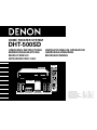 1
1
-
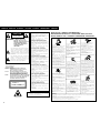 2
2
-
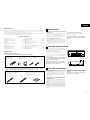 3
3
-
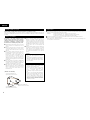 4
4
-
 5
5
-
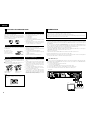 6
6
-
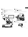 7
7
-
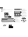 8
8
-
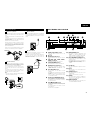 9
9
-
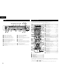 10
10
-
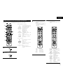 11
11
-
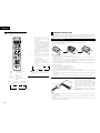 12
12
-
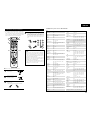 13
13
-
 14
14
-
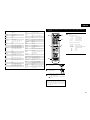 15
15
-
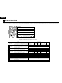 16
16
-
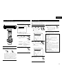 17
17
-
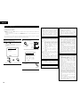 18
18
-
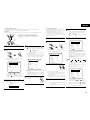 19
19
-
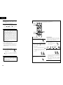 20
20
-
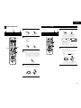 21
21
-
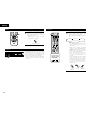 22
22
-
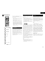 23
23
-
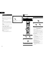 24
24
-
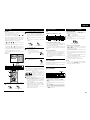 25
25
-
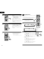 26
26
-
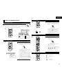 27
27
-
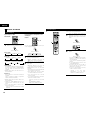 28
28
-
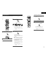 29
29
-
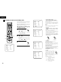 30
30
-
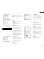 31
31
-
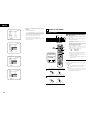 32
32
-
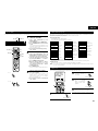 33
33
-
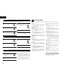 34
34
-
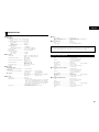 35
35
-
 36
36
-
 37
37


Denon DHT-500SD Operating Instructions Manual
- Categoria
- Lettori DVD
- Tipo
- Operating Instructions Manual
in altre lingue
- English: Denon DHT-500SD
Documenti correlati
-
Denon AVR-1306 Operating Instructions Manual
-
Denon DCD-700AE Manuale utente
-
-
-
-
Denon DCD-1500AE Manuale utente
-
-
Denon PMA-1500AE Manuale utente
-
-
Altri documenti
-
Samsung DVD-P171 Manuale utente
-
Samsung DVD-P370 Manuale utente
-
Sony DAV-SB100 Istruzioni per l'uso
-
TEAC CD-P1260MKII Manuale del proprietario
-
Sanyo RB-SL25 Manuale utente
-
 Ego Technology 4000 Plus Manuale utente
-
Panasonic SCVK31 Istruzioni per l'uso
-
-
Marantz CC4001 Manuale utente
-
Alpine DVE-5207 Manuale del proprietario
