Yamaha 01V96i Manuale utente
- Categoria
- Apparecchiature musicali supplementari
- Tipo
- Manuale utente
Questo manuale è adatto anche per

Reference Manual
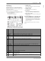
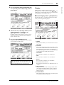
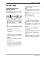
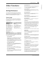
How to Use This
Reference Manual
The 01V96i Reference Manual (this document) allows you to
search for terms and take advantage of links in the text.
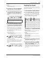
Searching for terms
To search for a term, use the search function of the software
you’re using to view this document.
If you’re using Adobe Reader, enter the term in the search box
and press the <Enter> key of your computer keyboard to
search for occurrences of that term.
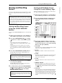
Displaying the next/previous
view
If you’re using Adobe Reader, you can jump to the previous/
next view in your viewing history. This is a convenient way to
jump back to the previous page after you’ve used a link to
jump to a different page.
Using the Function Tree
A function tree for the 01V96i is provided on page 4 and fol-
lowing. You can use this to quickly find the explanatory page
you want.
Note: The latest version of Adobe Reader can be downloaded
from the following URL.
http://www.adobe.com/products/reader.html
Note:
• If the Previous View / Next View buttons are not shown in the
toolbar, you can hold down your computer keyboard’s <Alt>
key and use the <←><→> keys to jump to the previous or next
view.
• For details on using other PDF-viewing software, refer to the
owner’s manual of the software you’re using.

2 Contents
01V96i—Reference Manual
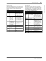
Contents
How to Use This Reference Manual ............................................... 1
Contents of the Owner’s Manual (Booklet) .......... 3
Function Tree .......................................................... 4
Control Surface & Rear Panel ................................. 6
Control Surface .................................................................................. 6
Rear Panel ......................................................................................... 10
Analog I/O & Digital I/O ...................................... 12
Analog Inputs & Outputs ............................................................... 12
Digital Inputs & Outputs ................................................................ 13
Converting Sampling Rates of Signals Received at I/O Card
Inputs ................................................................................. 14
Monitoring Digital Input Channel Status .................................... 14
Dithering Digital Outputs .............................................................. 15
Setting the Transfer Format for Higher Sampling Rates ........... 16
Input Channels ...................................................... 17
About Input Channels .................................................................... 17
Setting the Input Channels from the Display .............................. 18
Setting the Input Channels from the Control Surface ............... 25
Pairing Input Channels ................................................................... 26
Naming Input Channels ................................................................. 28
Bus Outs ................................................................ 29
About Stereo Out ............................................................................. 29
Bus Out 1–8 ...................................................................................... 29
Setting the Stereo Out and Bus Out 1–8 from the Display ........ 30
Setting the Stereo Out and Bus Out 1–8 from the Control
Surface ............................................................................... 33
Pairing Buses or Aux Sends ........................................................... 33
Attenuating Output Signals ........................................................... 34
Naming the Stereo Out and Bus Outs .......................................... 35
Aux Outs ................................................................ 36
Aux Out 1–8 ..................................................................................... 36
Setting Aux Out 1–8 from the Display ......................................... 36
Setting Aux Out 1–8 from the Control Surface ........................... 38
Setting Aux Send Levels .................................................................. 38
Viewing Aux Send Settings for Multiple Channels .................... 40
Panning Aux Sends ......................................................................... 41
Copying Channel Fader Positions to Aux Sends ........................ 42
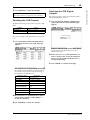
Input & Output Patching ..................................... 43
Input Patching ................................................................................. 43
Output Patching .............................................................................. 44
Patching Direct Outs ....................................................................... 46
Insert Patching ................................................................................. 47
Monitoring ............................................................ 49
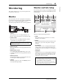
Monitor ............................................................................................. 49
Monitor and Solo Setup .................................................................. 49
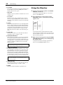
Using the Monitor ........................................................................... 50
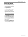
Using the Solo Function ................................................................. 51
Surround Pan ........................................................ 52
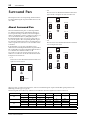
About Surround Pan ....................................................................... 52
Setting Up and Selecting Surround Pan Modes .......................... 53
Surround Panning ........................................................................... 56
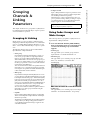
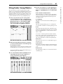
Grouping Channels & Linking Parameters .......... 59
Grouping & Linking ........................................................................ 59
Using Fader Groups and Mute Groups ........................................ 59
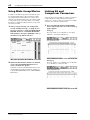
Using Fader Group Master ............................................................ 61
Using Mute Group Master ............................................................. 62
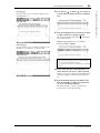
Linking EQ and Compressor Parameters .................................... 62
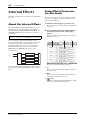
Internal Effects ..................................................... 64
About the Internal Effects .............................................................. 64
Using Effects Processors via Aux Sends ....................................... 64
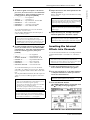
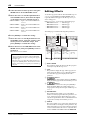
Inserting the Internal Effects into Channels ................................ 65
Editing Effects .................................................................................. 66
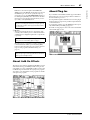
About Add-On Effects .................................................................... 67
About Plug-Ins ................................................................................. 67
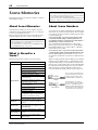
Scene Memories ................................................... 68
About Scene Memories ................................................................... 68
What is Stored in a Scene? .............................................................. 68
About Scene Numbers .................................................................... 68
Storing and Recalling Scenes .......................................................... 69
Auto Scene Memory Update .......................................................... 70
Fading Scenes ................................................................................... 71
Recalling Scenes Safely .................................................................... 72
Sorting Scenes ................................................................................... 72
Copying and Pasting a Scene (Global Paste) ............................... 73
Libraries ................................................................ 74
About the Libraries .......................................................................... 74
General Library Operation ............................................................. 74
Using Libraries ................................................................................. 75
Remote Control .................................................... 83
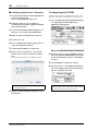
About Remote Function ................................................................. 83
Pro Tools Remote Layer ................................................................. 83
Nuendo/Cubase Remote Layer ...................................................... 93
Other DAW Remote Layer ............................................................. 94
MIDI Remote Layer ......................................................................... 94
Machine Control Function ............................................................. 98
MIDI .................................................................... 100
MIDI & the 01V96i ........................................................................ 100
MIDI Port Setup ............................................................................ 101
Assigning Scenes to Program Changes for Remote Recall ...... 103
Assigning Parameters to Control Changes for Real-time Control
.. 104
Controlling Parameters by Using Parameter Changes ............. 106
Transmitting Parameter Settings via MIDI (Bulk Dump) ....... 107
Other Functions ................................................. 109
Setting Preferences ......................................................................... 109
Creating a Custom Layer by Combining Channels
(User Assignable Layer) ................................................. 110
Cascading Consoles ....................................................................... 111
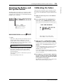
Checking the Battery and the System Version .......................... 113
Calibrating the Faders ................................................................... 113
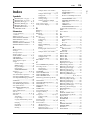
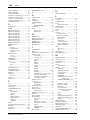
Index ................................................................... 115
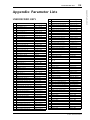
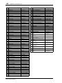
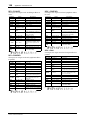
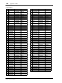
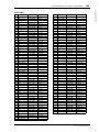
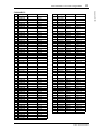
Appendix: Parameter Lists .............................. 119
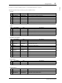
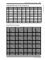
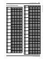
USER DEFINED KEYS ................................................................. 119
USER DEFINED KEYS Initial Assignments ............................. 121
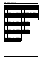
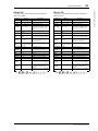
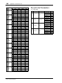
Input Patch Parameters ................................................................ 121
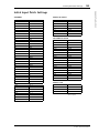
Initial Input Patch Settings ........................................................... 123
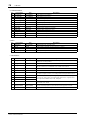
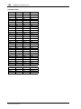
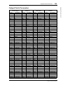
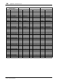
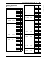
Output Patch Parameters ............................................................. 125
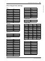
Initial Output Patch Settings ........................................................ 127
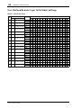
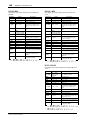
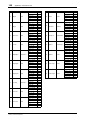
User Defined Remote Layer Initial Bank Settings ..................... 128
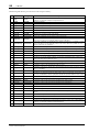
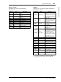
Effects Parameters ......................................................................... 132
Effects and tempo synchronization ............................................. 146
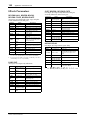
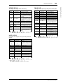
Preset EQ Parameters .................................................................... 147
Preset Gate Parameters (fs = 44.1 kHz) ...................................... 148
Preset Compressor Parameters (fs = 44.1 kHz) ......................... 149
Dynamics Parameters ................................................................... 151
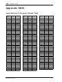
Appendix: MIDI ............................................... 156
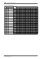
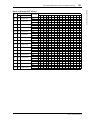
Scene Memory to Program Change Table ................................. 156
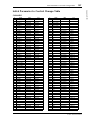
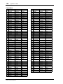
Initial Parameter to Control Change Table ............................... 157
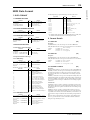
MIDI Data Format ......................................................................... 173
MIDI Implementation Chart ........... End of Manual

Contents of the Owner’s Manual (Booklet) 3
01V96i—Reference Manual
Contents of the Owner’s Manual (Booklet)
Contents of the
Owner’s Manual
(Booklet)
The contents of the separate Owner’s Manual booklet are as
follows.
PRECAUTIONS
Welcome
Package Contents
About the included discs
About the included DAW software
About the utility software
Firmware updates
About this Owner’s Manual
Conventions Used in this Manual
Control Surface & Rear Panel
Control Surface
Rear Panel
Installing an Optional Card
Operating Basics
About the Display
Selecting Display Pages
Display Interface
Selecting Layers
Selecting Channels
Selecting Fader Modes
Metering
Connections and Setup
Connections
Wordclock Connections and Settings
Input and Output Patching
Tutorial
Input and Output Patching
Setting the Input Levels
Pairing Channels
Setting the Routing
EQ’ing the Input Signals
Using the EQ Library
Compressing the Input Signals
Using the Internal Effects
Recording to DAW Software via the USB Port
Adjusting the Monitor Levels from the DAW
Using Scene Memories
Changing the Channel Names
Creating a Custom Layer by Combining Channels
(User Assignable Layer)
Using the Oscillator
Using the User Defined Keys
Using Operation Lock
Initializing
Troubleshooting
Error messages
Contents of the Reference Manual
Specifications
General Spec
Libraries
Analog Input Spec
Analog Output Specs
Digital Input Spec
Digital Output Spec
I/O SLOT Spec
MIDI/USB/WORD CLOCK I/O Spec
Dimensions
Options
Rack Mounting the 01V96i Using RK1 Rack Mount Kit
Index
01V96i Block Diagram
01V96i Level Diagram

4 Function Tree
01V96i—Reference Manual
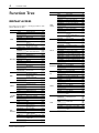
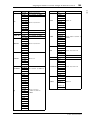
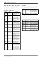
Function Tree
DISPLAY ACCESS
Page numbers in parentheses ( ) are the page numbers of the
Owner’s Manual (booklet).
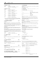
BUTTON FUNCTION PAGE NAME LINK
SCENE
SCENE SCENE MEMORY 68
IN FADE INPUT FADE TIME 71
OUT FADE OUTPUT FADE TIME 71
RCL SAFE RECALL SAFE 72
SORT SORT 72
PASTE SRC
GLOBAL PASTE SOURCE CH
SELECT
73
PASTE DST
GLOBAL PASTE
DESTINATION SCENE
73
DIO/SETUP
WORD CLOCK WORD CLOCK SELECT 14
FORMAT
HIGHER SAMPLE RATE
DATA TRANSFER FORMAT
14
15
16
PREFER1 PREFERENCES 1 109
PREFER2 PREFERENCES 2 110
MIDI/HOST MIDI/TO HOST SETUP 100
MONITOR MONITOR 49
REMOTE REMOTE 85
MACHINE MACHINE CONTROL 98
SURR BUS SURROUND BAS SETUP 54
CASCADE
CASCADE IN
ATTENUATION
112
OUTPUT ATT
OUTPUT PORT
ATTENUATOR
34
MIDI
SETUP MIDI SETUP 101
PGM ASGN
PROGRAM CHANGE
ASSIGN TABLE
102
CTL ASGN
CONTROL CHANGE
ASSIGN TABLE
104
BULK BULK DUMP 107
UTILITY
OSCILLATOR OSCILLATOR (45)
CH STATUS
CHANNEL STATUS
MONITOR
14
BATTERY BATTERY CHECK 113
USER DEF USER DEFINED KEY ASSIGN 119
LOCK OPERATION LOCK (47)
/INSERT/
DELAY
PHASE PHASE 18
INSERT INSERT 47
DLY 1-16 INPUT CH1-16 DELAY 18
DLY17-32 INPUT CH17-32 DELAY 18
OUT DLY OUTPUT DELAY 30
PAN/
ROUTING
PAN PAN 22
ROUT1-16 INPUT CH1-16 ROUTING 22
ROUT17-STI
INPUT CH17-32
ROUTING/ST IN
22
BUS TO ST BUS TO STEREO 31
SURR MODE SURROUND MODE 53
CH EDIT
SELECTED CHANNEL
SURROUND EDIT
56
SURR1-16 INPUT CH1-16 SURROUND 58
SURR17-32
INPUT CH17-32
SURROUND
58
SURR ST IN STEREO INPUT SURROUND 58
PAIR/
GROUP
INPUT INPUT PAIR 27
OUTPUT OUTPUT PAIR 33
IN FADER INPUT FADER GROUP 59
IN MUTE INPUT MUTE GROUP 59
OUT FADER OUTPUT FADER GROUP 59
OUT MUTE OUTPUT MUTE GROUP 60
IN EQ INPUT EQUALIZER LINK 62
OUT EQ OUTPUT EQUALIZER LINK 62
IN COMP INPUT COMP LINK 63
OUT COMP OUTPUT COMP LINK 63
IN MASTER
INPUT FADER GROUP
MASTER
61
OUT MASTER
OUTPUT FADER GROUP
MASTER
61
PATCH
IN PATCH INPUT PATCH 43
INPUT INS INPUT INSERT IN PATCH 48
EFFECT
EFFECT INPUT/OUTPUT
PATCH
64
CASCADE IN CASCADE IN PATCH 111
IN NAME INPUT CHANNEL NAME 28
IN LIB INPUT PATCH LIBRARY 75
OUT PATCH SLOT OUTPUT PATCH 44
USB OUT USB OUT PATCH 45
OUTPUT INS OUTPUT INSERT IN PATCH 48
DIRECT OUT DIRECT OUT DESTINATION 46
2TR OUT 2TR OUT DIGITAL PATCH 45
OUT NAME OUTPUT CHANNEL NAME 35
OUT LIB OUTPUT PATCH LIBRARY 76
DYNAMICS
GATE EDIT GATE EDIT 19
GATE LIB GATE LIBRARY 79
COMP EDIT COMP EDIT 20
COMP LIB COMP LIBRARY 79
EQ
EQ EDIT EQUALIZER EDIT 21
EQ LIBRARY EQUALIZER LIBRARY 81
IN ATT INPUT ATTENUATOR 20
OUT ATT OUTPUT ATTENUATOR 30
EFFECT
FX1 EDIT FX1 EDIT 66
FX2 EDIT FX2 EDIT 66
FX3 EDIT FX3 EDIT 66
FX4 EDIT FX4 EDIT 66
FX1 LIB FX1 LIBRARY 76
FX2 LIB FX2 LIBRARY 76
FX3 LIB FX3 LIBRARY 76
FX4 LIB FX4 LIBRARY 76
P-IN EDIT
PLUG-IN EFFECT CARD
EDIT
67
VIEW
PARAMETER PARAMETER VIEW
23
31
37
FADER FADER VIEW
24
32
38
LIBRARY CHANNEL LIBRARY 75
1-16 AUX INPUT CH1-16 AUX VIEW 40
17-STI AUX
INPUT CH17-ST IN AUX
VIEW
40
BUTTON FUNCTION PAGE NAME LINK

Function Tree 5
01V96i—Reference Manual
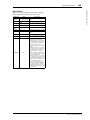
Function Tree
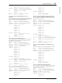
FADER MODE
LAYER
BUTTON FUNCTION PAGE NAME LINK
AUX1–
AUX8
SEND AUX1–AUX8 SEND 38
PAN AUX1–AUX8 PAN 41
VIEW1-16 INPUT CH1-16 AUX VIEW 40
VIEW17-STI
INPUT CH17-ST IN AUX
VIEW
40
HOME
(METER)
CH1-32 CH1-32 METER 8
ST IN ST IN METER 8
MASTER MASTER METER 8
EFFECT
EFFECT1-4 INPUT/OUTPUT
METER
8
STEREO STEREO METER 8
POSITION METER POSITION 8
BUTTON FUNCTION PAGE NAME LINK
1-16
8
17-32
8
MASTER
8
REMOTE
USER DEFINED 94
ProTools 83
Nuendo 93
Cubase 93
General DAW 94
USER
ASSIGNABLE
LAYER
110

6 Control Surface & Rear Panel
01V96i—Reference Manual
Control Surface & Rear Panel
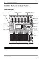
Control Surface
SOLO SOLO
ON ON
SOLO
ON
SOLO
ON
SOLO
ON
SOLO
ON
SOLO
ON
SOLO
ON
SOLO
ON
SOLO
ON
SOLO
ON
SOLO
ON
SOLO
ON
SOLO
ON
SOLO
ON
SOLO
ON
SOLO
ON
SOLO
ONON
PEAK
SIGNAL
PEAK
SIGNAL
PEAK
SIGNAL
PEAK
SIGNAL
PEAK
SIGNAL
PEAK
SIGNAL
PEAK
SIGNAL
PEAK
SIGNAL
PEAK
SIGNAL
PEAK
SIGNAL
PEAK
SIGNAL
PEAK
SIGNAL
PEAK
SIGNAL
PEAK
SIGNAL
1-16 17-32 MASTER REMOTE
LAYER
SEL SEL SEL SEL SEL SEL SEL SEL SEL SEL SEL SEL SEL SEL SEL SEL SEL SELSEL
ST IN
ENTER
STEREO
DEC INC
SOLO CLEAR
RECALL
STORE
SCENE MEMORY
PHONES
MONITOR
OUT
MONITOR
2TR IN
CH15
/
16
2TR IN
LEVEL
PHONES
LEVEL
0
10
0
10
+4
-26
GAIN
+4
-26
GAIN
+4
-26
GAIN
GAIN
+4
-26
GAIN
20dB
-16
-60
GAIN
20dB
-16
-60
GAIN
20dB20dB20dB20dB20dB20dB20dB20dB20dB20dB
-16
-60
GAIN
-16
-60
GAIN
-16
-60
GAIN
-16
-60
GAIN
-16
-60
GAIN
-16
-60
GAIN
-16
-60
GAIN
-16
-60
GAIN
-16
-60
GAIN
-16
-60
PA D
FADER MODE
DISPLAY ACCESS
AUX 1
AUX 1 AUX 2 AUX 3 AUX 4 AUX 5 AUX 6 AUX 7 AUX 8 BUS 1 BUS 2 BUS 3 BUS 4 BUS 5 BUS 6 BUS 7 BUS 8
AUX 2 AUX 3 AUX 4
AUX 8AUX 7AUX 6AUX 5
HOME (METER)
DYNAMICS
EQ EFFECT VIEW
PATCH
UTILITYMIDISCENE
DIO/SETUP
/ INSERT/
DELAY
PAN/
ROUTING
PAIR/
GROUP
A
B
A
B
A
B
A
B
A
B
A
B
A
B
A
B
A
B
A
B
A
B
A
B
16
1513
121110987643215
14
INSERT I
/
O INSERT I
/
O INSERT I
/
O INSERT I
/
O INSERT I
/
O INSERT I
/
O INSERT I
/
O INSERT I
/
O INSERT I
/
O INSERT I
/
O INSERT I
/
O INSERT I
/
O
L
R
IN OUT
2TR
-10dBV (UNBAL)
PHANTOM +48V
CH9-12CH5-8CH1-4
INPUT
(BAL)
INSERT
OUT IN
(UNBAL)
ST IN 1 ST IN 2
USER DEFINED
KEYS
12
34
56
78
55
5
+10
5
1010
10
1515
15
2020
20
303030
30
4040
40
5050
50
6060
7070
20
30
40
40
50
50
60
70
00
5
10
15
20
0
0
5
+10
5
10
15
30
20
30
40
40
50
50
60
70
20
30
40
40
50
50
60
70
20
30
40
40
50
50
60
70
20
30
40
40
50
50
60
70
20
30
40
40
50
50
60
70
15
0
5
10
15
20
0
5
+10
5
10
0
30
15
5
10
15
20
0
5
+10
5
10
0
30
15
5
10
15
20
0
5
+10
5
10
0
30
15
5
10
15
20
0
5
+10
5
10
0
30
15
20
30
40
40
50
50
60
70
30
15
20
30
40
40
20
30
40
20
30
40
20
30
40
50
50505050
20
30
40
50
20
30
40
50
60
70
40
50
60
70
40
50
60
70
40
50
60
70
40
50
60
70
40
50
60
70
40
50
60
70
40
50
60
70
30
15
5
10
15
20
0
5
+10
5
10
0
5
10
15
20
0
5
+10
5
10
0
5
10
15
20
0
30
5
10
15
20
0
30
5
10
15
20
0
30
5
10
15
20
0
30
5
10
15
20
0
303030
5
10
15
20
0
5
10
15
20
0
5
10
15
20
0
5
+10
5
10
0
15
5
+10
5
10
0
15
5
+10
5
10
0
15
5
+10
5
10
0
15
20
30
40
50
15 15
20
30
40
50
15
5
+10
5
10
0
5
+10
5
10
0
5
+10
5
10
0
5
+10
5
10
0
123456
123456
7
8 9 10 11 12
7
8 9 10 11 12
13 14 15 16
13 14 15 16
32313029282726252423222120191817
STEREO
13 14 15 16
OVER
0
-3
-6
-9
-12
-15
-18
-24
-30
-36
-48
HIGH
HIGH-MID
LOW-MID
LOW
Q
FREQUENCY
GAIN
AD Input Section (p. 7)
SELECTED
CHANNEL
Section (p. 9)
Monitor Out
& Head-
phones Sec-
tion (p. 7)
SOLO Section
(p. 9)
Channel Strip Section (p. 7) STEREO Section (p. 8) USER DEFINED KEYS
Section (p. 9)
Data Entry
Section (p. 9)
LAYER Section
(p. 8)
SCENE MEMORY Section (p. 9)
Display Section
(p. 9)
DISPLAY ACCESS
Section (p. 8)
ST IN Section
(p. 8)
FADER MODE
Section (p. 8)
Note: For details on the function of each item, refer to “Control Surface & Rear Panel” in the Owner’s Manual.

Control Surface 7
01V96i—Reference Manual
Control Surface & Rear Panel
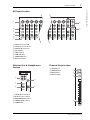
AD Input Section
1 INPUT connectors A/B
2 INPUT connectors 13–16
3 INSERT I/O connectors
4 PAD switches
5 GAIN controls
6 PEAK indicators
7 SIGNAL indicators
8 AD15/16 selector
Monitor Out & Headphones
Section
1 2TR IN/OUT connectors
2 Monitor Source selector
3 MONITOR LEVEL control
4 PHONES LEVEL control
5 PHONES jack
Channel Strip Section
1 [SEL] buttons
2 [SOLO] buttons
3 [ON] buttons
4 Channel faders
PEAK
SIGNAL
PEAK
SIGNAL
PEAK
SIGNAL
PEAK
SIGNAL
PEAK
SIGNAL
PEAK
SIGNAL
PEAK
SIGNAL
PEAK
SIGNAL
PEAK
SIGNAL
PEAK
SIGNAL
PEAK
SIGNAL
CH15
/
16
2TR IN
+4
-26
GAIN
+4
-26
GAIN
+4
-26
GAIN
GAIN
+4
-26
GAIN
20dB
-16
-60
GAIN
20dB
-16
-60
GAIN
20dB20dB20dB20dB20dB20dB20dB
-16
-60
GAIN
-16
-60
GAIN
-16
-60
GAIN
-16
-60
GAIN
-16
-60
GAIN
-16
-60
GAIN
-16
-60
PAD
A
B
A
B
A
B
A
B
A
B
A
B
A
B
A
B
A
B
16
1513
121110943215
14
INSERT I
/
O INSERT I
/
O INSERT I
/
O INSERT I
/
O INSERT I
/
O INSERT I
/
O INSERT I
/
O INSERT I
/
O INSERT I
/
O
CH1-4
INPUT
(BAL)
INSERT
OUT IN
(UNBAL)
13 14 15 16
1
3
4
5
6
7
8
2
PHONES
MONITOR
OUT
MONITOR
2TR IN
LEVEL
PHONES
LEVEL
0
10
0
10
L
R
IN OUT
2TR
-10dBV
(UNBAL)
PHANTOM +48V
CH9-12CH5-8
1
2
3
4
5
SOLO
ON
SEL
AUX 1
40
50
60
70
30
5
10
15
20
0
20
30
40
50
15
5
+10
5
10
0
1
1
17
1
2
3
4

8 Control Surface & Rear Panel
01V96i—Reference Manual
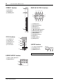
STEREO Section
1 [SEL] button
2 [ON] button
3 [STEREO] fader
ST IN Section
1 [ST IN] button
2 [SEL] buttons
3 [SOLO] buttons
4 [ON] buttons
5 Level controls
FADER MODE Section
1 [AUX 1]–[AUX 8] buttons
2 [HOME] button
DISPLAY ACCESS Section
1 [SCENE] button
2 [DIO/SETUP] button
3 [MIDI] button
4 [UTILITY] button
5 [ /INSERT/DELAY] button
6 [PAN/ROUTING] button
7 [PAIR/GROUP] button
8 [PATCH] button
9 [DYNAMICS] button
0 [EQ] button
A [EFFECT] button
B [VIEW] button
LAYER Section
1 [1–16]/[17–32] buttons
2 [MASTER] button
3 [REMOTE] button
ON
SEL
5
10
15
20
30
40
50
60
70
0
STEREO
1
2
3
SOLO
ON
SOLO
ON
SEL SEL
ST IN
ST IN 1 ST IN 2
1
2
3
4
5
FADER MODE
AUX
1
AUX
2
AUX
3
AUX
4
AUX
8
AUX
7
AUX
6
AUX
5
HOME (METER)
1
2
Tip: The ST IN section is not affected by the layer settings.
DISPLAY ACCESS
DYNAMICS
EQ EFFECT VIEW
PATCH
UTILITYMIDISCENE
DIO/SETUP
/ INSERT/
DELAY
PAN/
ROUTING
PAIR/
GROUP
1 2 3
9
0 A B
4
5
6
8
7
UTILITYMIDISCENE
DIO/SETUP
1-16 17-32 MASTER REMOTE
LAYER
1 2 3

Control Surface 9
01V96i—Reference Manual
Control Surface & Rear Panel
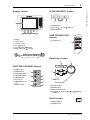
Display Section
1 Display
2 Stereo meters
3 Contrast control
4 [F1]–[F4] buttons
5 Left Tab Scroll [ ] button
6 Right Tab Scroll [ ] button
SELECTED CHANNEL Section
1 [PAN] control
2 [HIGH] button
3 [HIGH-MID] button
4 [LOW-MID] button
5 [LOW] button
6 [Q] control
7 [FREQUENCY] con-
trol
8 [GAIN] control
SCENE MEMORY Section
1 [STORE] button
2 Scene Up [ ] / Down [ ] buttons
3 [RECALL] button
USER DEFINED KEYS
Section
1 [1]–[8] buttons
Data Entry Section
1 Parameter wheel
2 [ENTER] button
3 [DEC] & [INC] buttons
4 Left, Right, Up, Down ([ ]/[ ]/[ ]/[ ]) cur-
sor buttons
SOLO Section
1 [SOLO] indicator
2 [CLEAR] button
STEREO
OVER
0
-3
-6
-9
-12
-15
-18
-24
-30
-36
-48
4
1
5
2
3
6
Tab Scroll arrow
HIGH
HIGH-MID
LOW-MID
LOW
Q
FREQUENCY
GAIN
2
3
4
5
6
1
7
8
RECALL
STORE
SCENE MEMORY
2
13
USER DEFINED
KEYS
12
34
56
78
1
ENTER
DEC INC
2
3
1
4
SOLO CLEAR
1 2

10 Control Surface & Rear Panel
01V96i—Reference Manual
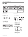
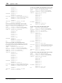
Rear Panel
PHANTOM +48V
1 CH1–4 ON/OFF switch
2 CH5–8 ON/OFF switch
3 CH9–12 ON/OFF switch
AD Output Section
1 MONITOR OUT connectors L/R
2 OMNI OUT connectors 1–4
3 STEREO OUT connectors L/R
Digital I/O Section
1 WORD CLOCK OUT connector
2 WORD CLOCK IN connector
3 ADAT IN/OUT connectors
4 2TR OUT DIGITAL COAXIAL
5 2TR IN DIGITAL COAXIAL
MIDI/USB Section
1 MIDI IN/THRU/OUT ports
2 TO HOST USB port
PHANTOM +48V (p. 10)
Power Section (p. 11)
AD Output Section
(p. 10)
SLOT Section (p. 11)
MIDI/USB Section
(p. 10)
Digital I/O Section
(p. 10)
321
321
42153
21

Rear Panel 11
01V96i—Reference Manual
Control Surface & Rear Panel
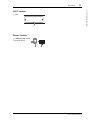
SLOT Section
1 SLOT
Power Section
1 POWER ON/OFF switch
2 AC IN connector
1
21

12 Analog I/O & Digital I/O
01V96i—Reference Manual
Analog I/O &
Digital I/O
This chapter describes the 01V96i’s analog and digital
input/output connectors as well as the basic operations
involving the digital I/Os.
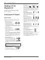
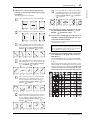
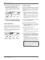
Analog Inputs & Outputs
Input Section
The 01V96i’s top panel features input connectors, which
enable you to connect microphone and line-level sources.
• INPUT connectors A 1–12
These balanced TRS-type
phone connectors accept
line-level and microphone sig-
nals. The nominal input range is
–60 dB through +4 dB. The phantom [+48V] switches on
the rear panel turn on or off the +48V phantom power
feed to these inputs.
• INPUT connectors B 1–12
These balanced TRS-type con-
nectors accept line-level and
microphone signals. The nominal input range is –60 dB
through +4 dB.
You cannot use same-numbered INPUT A and INPUT B
connectors simultaneously. (For example, you cannot use
INPUT A-2 and INPUT B-2 at the same time.) If you
connect cables to A and B connectors of the same num-
ber, only the signal from INPUT B is effective (e.g., B-2
takes priority over A-2).
•INPUT connectors 13–16
These balanced TRS-type phone con-
nectors accept line-level signals. When
the AD 15/16 source selector is turned
on (pushed in), signals from INPUT 15
and 16 are ignored. Instead, signals from
the 2TR IN connector will be routed to AD Input Chan-
nels 15 and 16.
• INSERT I/O connectors
These TRS-type phone connectors
are used to insert external devices,
such as effects processors, into AD Input Channels.
•Phantom Power
Inputs 1 through
12 feature switch-
able +48V phantom powering for use with con-
denser-type microphones and direct boxes. The phantom
[+48V] switches on the rear panel turn on or off the +48V
phantom power feed to the corresponding inputs.
•PAD switches
Inputs 1 through 12 feature pad
switches, which attenuate input
signals by 20 dB. These switches
are effective on both INPUT A and B signals.
•GAIN controls
Inputs 1 through 16 feature
rotary gain controls that adjust
input sensitivity. Input sensitivity
for INPUT connectors 1–12
ranges from –16 dB to –60 dB when the Pad is off, and
from +4 dB to –40 dB when the Pad is on. Input sensitiv-
ity for INPUT connectors 13–16 ranges from +4 dB to
–26 dB.
•PEAK & SIGNAL Indicators
The SIGNAL indicator lights up
when the input signal level at
INPUTs 1–16 exceeds –34 dB.
The PEAK indicator lights up when the input signal level
is 3 dB below clipping.
•2TR IN connectors
These unbalanced RCA phono connec-
tors accept line-level signals from
devices such as CD players.
When the AD 15/16 source selector is
turned on (pushed in), signals input at
these conductors are routed to AD
Inputs 15 and 16. When the Monitor source selector is
turned on (pushed in), you can monitor these signals
from the MONITOR OUT connectors.
Tip: You can patch signals input from the INPUT connectors
to any Input Channels. (See page 43 for information on
patching input signals to Input Channels.)
AA
21
BB
INPUT
(BAL)
16
1513
14
INSERT I
/
O INSERT I
/
O
INSERT
OUT IN
(UNBAL)
20dB
PAD
20dB
GAIN
-16
-60
PEAK
SIGNAL
GAIN
L
R
IN OUT
2TR
-10dBV
(UNBAL)

Digital Inputs & Outputs 13
01V96i—Reference Manual
Analog I/O & Digital I/O
Output Section
The 01V96i top and rear panels feature output connectors
that enable you to connect a monitoring system, effects pro-
cessors and other line-level devices.
• MONITOR OUT connectors L/R
These balanced TRS-type phone con-
nectors output monitoring signals or
input signals routed from the 2TR IN
connectors. The nominal output level
is +4 dB.
Use the Monitor source selector in the Monitor Out &
Headphones section to select the signal output from these
connectors.
•OMNI OUT connectors 1–4
These balanced
TRS-type phone con-
nectors output any Bus
Outs or Input Channel
Direct Outs. The nomi-
nal output level is +4 dB.
• STEREO OUT connectors L/R
These balanced XLR-3-32-type
connectors output the Stereo Out
signals. The nominal output level
is +4 dB.
•2TR OUT connectors
These unbalanced RCA phono con-
nectors output line-level signals to a
connected recorder or other external
device. These connectors always out-
put the Stereo Out signals.
Digital Inputs & Outputs
The 01V96i rear panel features digital input and output con-
nectors that enable you to connect external digital devices.
Any signal path can be patched to these digital inputs and
outputs.
You can also add analog and digital I/Os by installing an
optional I/O card in the slot.
Digital I/O Connectors
•2TR IN DIGITAL connector
2TR IN DIGITAL is an RCA phono connector
and accepts consumer format (IEC 60958)
digital audio. You can patch digital signals
input at this connector to any Input Channel
(page 43).
• 2TR OUT DIGITAL connector
This RCA phono connector outputs con-
sumer format (IEC 60958) digital audio. You
can patch any Bus outs or Input channel
Direct Outs to this output (page 45).
•ADAT IN connector
This TOSLINK connector accepts 8-channel ADAT opti-
cal format signals, which can be patched to any Input
Channel (page 43).
• ADAT OUT connector
This TOSLINK connector outputs an 8-channel ADAT
optical format signal. You can patch any Bus Outs or
Input Channel Direct outs to this output (page 44).
SLOT
This slot allows you to install an optional mini-YGDAI
(Yamaha General Digital Audio Interface) I/O card. This card
offers AD/DA conversion, and various analog I/O options
and digital I/O interfaces in all the popular digital audio inter-
connect formats, including AES/EBU, ADAT, and Tascam.
You can patch signals input at these card connectors to any
Input Channels or Insert Ins (see page 43).
You can patch the card outputs to Bus Outs or Input Channel
Direct Outs (see page 46).
For details on the mini-YGDAI I/O cards that are currently
usable, refer to “I/O Slot Specifications” in the Owner’s Man-
ual.
For the latest information about mini-YGDAI I/O cards, refer
to the Yamaha Professional Audio website.
http://www.yamahaproaudio.com/
Tip: Any signal path can be patched to the OMNI OUT con-
nectors. (See page 44 for more information on patching sig-
nals to the OMNI OUT connectors.)
L
R
IN OUT
2TR
-10dBV
(UNBAL)

14 Analog I/O & Digital I/O
01V96i—Reference Manual
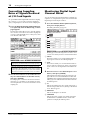
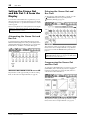
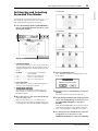
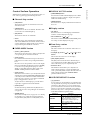
Converting Sampling
Rates of Signals Received
at I/O Card Inputs
An optional MY8-AE96S Digital I/O card features sampling
rate converters, so you can easily convert the sampling fre-
quency of digital inputs to the current 01V96i sampling rate.
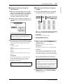
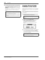
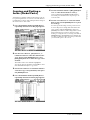
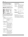
1. Press the DISPLAY ACCESS [DIO/SETUP] but-
ton repeatedly until the DIO/Setup | Format
page appears.
Use the buttons in the SRC sections to turn the sampling
rate converters on and off. You can turn the sampling rate
converters of the digital I/O card on or off in pairs (odd &
even channels, in this order).
2. Use the cursor buttons to move the cursor to
any two-channel button in the SRC sections,
then press [ENTER].
The sampling rate converter for the selected 2-channel
input turns on or off. When on, the sampling rate of the
received digital audio is converted to the 01V96i’s current
sampling rate.
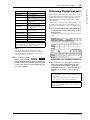
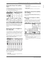
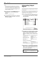
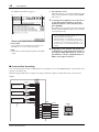
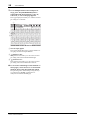
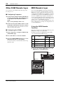
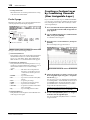
Monitoring Digital Input
Channel Status
You can view and monitor the Channel Status (sampling rate,
emphasis, etc.) of digital audio signals connected to the 2TR
Digital Inputs and Slot Inputs as follows.
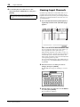
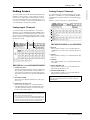
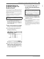
1. Press the DISPLAY ACCESS [UTILITY] button,
then press the [F2] button.
The Utility | CH Status page appears.
On this page, use the following buttons to select a slot or
connector for which you want to view the channel status.
1 2TR IN
This button enables you to view the Channel Status of
input signals connected to the 2TR Digital Inputs.
2 SLOT
These buttons enable you to view the Channel Status of
each two adjacent (odd and even, in this order) channel
signals connected to the digital I/O card installed in the
slot.
2. Move the cursor to the desired input or slot
button, then press [ENTER].
Channel Status information for the selected input is dis-
played. However, if a mini-YGDAI I/O card other than
AES/EBU format is installed, Channel Status information
will be grayed out. Channel Status information includes
the following items:
3 FS
Indicates the sampling rate. If no signal is being input, or
if the incoming wordclock is not synching to the internal
clock, “Unlock” appears.
4 EMPHASIS
Indicates the Emphasis on/off status.
5 CATEGORY
Indicates the status of “Category Code Bit” included in
the IEC958 Part 2 (S/PDIF-Consumer) format. This
parameter can display the following values:
Tip: The FS box on the Word Clock page displays the sam-
pling frequency at which the 01V96i is currently operating.
Note: The sampling rate converter is available only on the
Yamaha MY8-AE96S Digital I/O card. If you have installed
another type of I/O card in the slot, or if no card is installed
in the 01V96i, the buttons in the SRC sections are disabled.
1
2
3
4
5
6

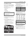
Dithering Digital Outputs 15
01V96i—Reference Manual
Analog I/O & Digital I/O
6 COPY
Indicates the status of copy protection information
included in the IEC958 Part2 (S/PDIF-Consumer) for-
mat signals. “OK” appears if copying is allowed. “Pro-
hibit” appears if copy-protected.
3. If you select the SLOT
button for a slot that
has an MY16-AE card installed, use the 01–08
and 09–16 buttons located in the lower-right
corner of the screen to select a channel group
you wish to display.
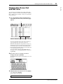
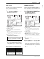
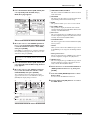
Dithering Digital Outputs
When digital audio is transferred to lower-resolution systems,
truncated bits may generate unpleasant noise. To cancel the
audible effect of this noise, a small complement of noise is
intentionally added to the digital outputs. This process is
called “dithering.”
On the 01V96i, you can dither the 2TR Digital Outputs and
Slot Outputs. For example, you can apply dithering to the
01V96i stereo mix data and record to a 16-bit digital recorder.
1. Press the DISPLAY ACCESS [DIO/SETUP] but-
ton repeatedly until the DIO/Setup | Format
page appears.
The dithering settings are displayed at the bottom of the
page.
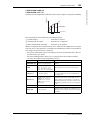
2. Move the cursor to the output or channel to
which you want to apply dithering, then
rotate the Parameter wheel or press the
[INC]/[DEC] buttons to select the value that
matches the resolution of the receiving
device.
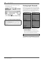
Parameter value Description
General Temporarily used
Laser Optical Laser optical device
D/D Conv
Digital - Digital converter and
signal processing device
Magnetic
Magnetic tape device and mag-
netic disk device
D.Broadcast Digital broadcast reception
Instruments
Musical instrument, micro-
phone, and sources that gener-
ate string signals
A/D Conv
A/D converter (without copy-
right information)
A/D Conv with (C)
A/D converter (with copyright
information)
Solid Memory Solid memory device
Experimental Experimental device
Unknown Unknown
Note: “AES/EBU” appears in the Category row when you are
monitoring IEC958 Part 3 (AES/EBU-Professional) format
signals (that do not include Category Code Bit).
Note:
• You cannot apply dithering to outputs or channels that are
set to “OFF.”
• Dithering is effective only when the resolution of the
receiving device is lower than that of the 01V96i.
Tip: To copy the currently-selected setting to all channels,
double-click the [ENTER] button. The copy confirmation
window is displayed.

16 Analog I/O & Digital I/O
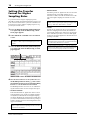
01V96i—Reference Manual
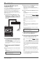
Setting the Transfer
Format for Higher
Sampling Rates
To operate the 01V96i at higher sampling frequencies
(88.2 kHz or 96 kHz) and transfer digital audio signals to and
from connected external devices, you must set the data trans-
fer format in accordance with the sampling frequencies sup-
ported by the external devices.
1. Press the DISPLAY ACCESS [DIO/SETUP] but-
ton repeatedly until the DIO/Setup | Word
Clock page appears.
2. Select INT88.2k or INT96k as the wordclock
source.
3. Press the DISPLAY ACCESS [DIO/SETUP] but-
ton repeatedly until the DIO/Setup | Format
page appears.
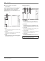
4. Use the cursor buttons to move the cursor to
an IN/OUT parameter field (
1), then rotate
the Parameter wheel or press the [INC]/[DEC]
buttons to set the data transfer format.
The IN/OUT parameters are used to set one of the follow-
ing data transfer formats for each slot input and output.
• DOUBLE CHANNEL
In Double Channel mode, digital audio data is received
and transmitted as mono signals at a sampling rate that is
exactly half (44.1/48 kHz) the current higher sampling
rate. Data is handled by two channels. This is useful when
you want to transfer data between the 01V96i operating at
a higher sampling rate and an external digital device that
supports 44.1/48 kHz.
•DOUBLE SPEED
In Double Speed mode, digital audio data is received and
transmitted at the current high sampling rate (i.e.,
88.2 kHz or 96 kHz). Select this mode if the devices that
support the higher sampling rates transmit or receive
data.
•SINGLE
In Single mode, digital audio data is received and trans-
mitted at a sampling rate that is half (44.1/48 kHz) the
current higher sampling rate of the 01V96i. For example,
this is useful when you want to receive 44.1 kHz digital
signals from an external digital device while the 01V96i is
operating at 88.2 kHz.
Note: When the 01V96i operates at a high sampling rate
(88.2 kHz or 96 kHz), only two internal effects processors are
available.
Note: Double Channel mode reduces the total number of
inputs or outputs on the corresponding slot. The even-num-
bered channels are disabled.
1
Note: You can select this setting only for slots in which a dig-
ital I/O card that inputs/outputs double-speed digital audio
data (e.g., MY8-AE96, MY8-AE96S) is installed.
Note: You cannot select this setting for slots in which a digital
I/O card that inputs/outputs double-speed digital audio data
(e.g., MY8-AE96, MY8-AE96S) is installed.
Tip: The parameter fields display “–” if the slot contains no
I/O card or if an AD/DA card or other I/O card that does not
allow you to set the transfer format has been installed.

Input Channels 17
01V96i—Reference Manual
Input Channels
Input Channels
This chapter describes how to adjust the 01V96i’s Input
Channel parameters.
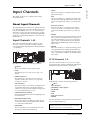
About Input Channels
The input Channel section enables you to adjust the level and
tone of the signals input to the 01V96i (and the signals output
from the internal Effects processors 1–4), and route the sig-
nals to Buses 1–8, the Stereo Bus, and Aux Sends 1–8. There
are two types of Input Channels, each featuring slightly differ-
ent functions: monaural Input Channels 1–32 and stereo ST
IN Channels 1–4.
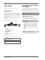
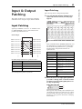
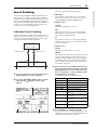
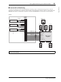
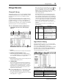
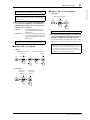
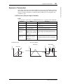
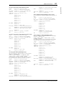
Input Channels 1–32
Each of these monaural Input Channels features a phase
effect, gate, compressor, attenuator, and EQ for signal pro-
cessing. The following diagram illustrates the Input Channel
1–32 signal flow.
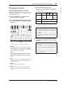
Input Channels 1–32 feature the following parameters:
• (Phase)
This section switches the phase of input signals.
•GATE
This dynamics processor can be used as a gate or for
ducking.
•COMP (Compressor)
This dynamics processor can be used as compressor,
expander or limiter. The compressor can be pre-EQ,
pre-fader, or post-fader.
•ATT (Attenuator)
This section enables you to attenuate or amplify the level
of signals that will be input to the EQ. The attenuator
enables you to prevent post-EQ signals from clipping and
to correct signal levels that are too low.
• 4 BAND EQ (4-band equalizer)
This parametric EQ features four bands (high, high-mid,
low-mid, and low).
• INPUT DELAY (Input delay)
This section enables you to delay input signals. You can
use this delay to fine-tune the timing between channels,
or as a delay effect with feedback.
• ON (On/Off)
This section enables you to turn the channel on or off.
The channel is muted with the Off setting.
•LEVEL
This section enables you to adjust the input level of the
Input Channel signal.
•PAN
This section enables you to adjust the pan setting of the
signals routed from the Input Channels to the Stereo Bus.
You can also apply the pan setting to a pair of Bus chan-
nels.
• AUX (Aux Send level)
This section enables you to adjust the level of signals
routed to Aux Sends 1–8. The signals can be routed to
Aux Sends from either the pre-fader or post-fader posi-
tion.
•INSERT
This section enables you to patch input signals to external
devices via the on-board I/O connectors or I/O card, or
insert the internal effect processors. You can patch any
inputs, outputs, or I/O card channels. (Note that this is
different from the INSERT I/O connectors in the AD
Input section.)
• METER
This section enables you to switch the metering position
of the signal levels that are displayed in the Meter page.
For more information on selecting the metering position,
refer to “Viewing the Level Meters” in the Owner’s Man-
ual (booklet).
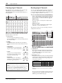
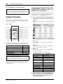
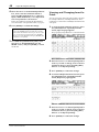
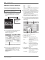
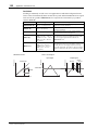
ST IN Channels 1–4
These stereo channels enable you to process stereo signals
using the phase effect, attenuator, and EQ. The following dia-
gram illustrates the ST IN Channel 1–4 signal flow.
ST IN Channels 1–4 feature the following parameters:
• (Phase)
•ATT (Attenuator)
• 4 BAND EQ (4-band equalizer)
• ON (On/Off)
•LEVEL
•PAN
• AUX (Aux Send level)
• METER
For more information on each parameter, refer to the preced-
ing section Input Channel 1–32.
INPUT PATCH
Tip: You can store these channel parameter settings in the Chan-
nel library. You can also store the Gate, Compressor, and EQ
parameter settings to the corresponding libraries.
INPUT PATCH

18 Input Channels
01V96i—Reference Manual
Setting the Input
Channels from the
Display
To set the Input Channel parameters, you can either move the
cursor to the desired parameter on the display and change the
value, or operate the desired button or control on the top
panel to directly change the setting.
This section explains how to set the parameters via the dis-
play.
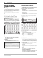
Switching the Signal Phase
To switch the phase of each Input Channel, press the
[ /INSERT/DELAY] button repeatedly until the following
/INS/DLY | Phase page appears.
Move the cursor to the NOR/REV button of the channel for
which you want to change the phase, then press the [ENTER]
or [INC]/[DEC] buttons to change the setting.
1 NOR/REV
These buttons switch the corresponding Input Channel
phase. NOR buttons indicate normal phase, and REV
buttons indicate reversed phase.
2 GLOBAL
The GLOBAL NOR/REV buttons allow you to set the
phase for all Input Channels simultaneously.
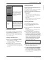
Delaying Input Channels
To set the delay for each channel, press the
[ /INSERT/DELAY] button repeatedly until the page listed
below that contains the desired channels appears.
• DLY 1-16 page
This page enables you to set the Delay function for Input
Channels 1–16.
• DLY 17-32 page
This page enables you to set the Delay function for Input
Channels 17–32.
The parameters on these two pages (and the procedure for
setting them) are the same.
1 DELAY SCALE
The following buttons determine the units of the delay
value shown below the msec value.
• meter ........................Units are set to meters.
• feet ............................Units are set to feet.
• sample......................Units are set to samples.
• beat ...........................Units are set to beats.
• frame........................Units are set to timecode frames.
2 GANG button
When this button is turned on (highlighted), the delay
time for each channel in a channel pair can be set simul-
taneously. When this option is turned off, the delay time
can be set for each channel in a channel pair individually.
3 Channel section
You can set individual delay parameters here. The delay
parameters include the following items:
•ON/OFF
This button switches the corresponding channel delay on
or off.
•msec
This parameter sets the delay time in milliseconds.
• meter/feet/sample/beat/frame
The delay time can be set using units of meters, feet, sam-
ples, beats, or frames, which you select by using the
DELAY SCALE buttons.
Tip:
• The name of the currently-selected channel is indicated in the
upper-right corner of the screen.
• You can set the phase separately for each of the ST IN Channels
or for each channel in a channel pair. If you selected the desired
ST IN Channel using the corresponding [SEL] button, pressing
the same [SEL] button repeatedly will toggle between channels
L and R.
1
2
213

Setting the Input Channels from the Display 19
01V96i—Reference Manual
Input Channels
•MIX
This parameter sets the mix balance of dry (Input Chan-
nel) and wet (delayed) signals.
•FB.GAIN
This parameter sets the amount of delay feedback.
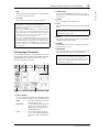
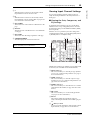
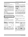
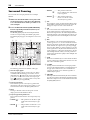
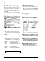
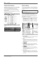
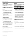
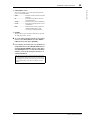
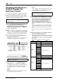
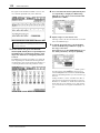
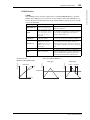
Gating Input Channels
To set the Input Channel gates, use the [SEL] buttons to select
the desired Input Channel, then press the DISPLAY ACCESS
[DYNAMICS] button, then press the [F1] button. The
Dynamics | Gate Edit page appears.
1 KEYIN SOURCE
Select one of the following buttons to determine the trig-
ger source for the currently-selected Input Channel’s gate.
• SELF......................... The selected channel’s own input sig-
nal is the trigger source.
• CHANNEL ............. Another Channel’s input signal is the
trigger source. Select the desired
channel in the parameter box below
the CHANNEL button.
• AUX ......................... An Aux Send signal is the trigger
source. Select the desired bus in the
parameter box below the AUX but-
ton.
2 STEREO LINK
This parameter’s ON/OFF button enables you to pair
gates for stereo operation even when the Input Channels
are not paired.
3 CURVE
This area displays the current gate curve.
4 TYPE
This area displays the current gate type (GATE or DUCK-
ING).
5 Meters
These meters indicate the levels of the post-gate signals
and the amount of gain reduction.
6 ON/OFF
The ON/OFF button turns the currently-selected Input
Channel’s gate on or off.
7 PARAMETER
These controls enable you to set the gate parameters. (See
page 148 for more information on the parameters.)
Tip:
• This function is unavailable for the ST IN Channels.
• The delay time range depends on the sampling rate at which
the 01V96i is operating.
• If you select the DELAY SCALE meter or feet button, the dis-
tance value can be converted to the delay time based on sonic
speeds (about 343.59 m/sec at 20 degrees Celsius). This option
is useful if you wish to correct the timing difference between
two sound sources that are far apart.
• If you select the DELAY SCALE beat button, a parameter box
for setting a note that represents the beat and a parameter box
for a tempo (BPM) setting appear below the DELAY SCALE
parameter. Setting the note and BPM settings in these param-
eter boxes enables you to set a delay time that synchronizes to
the song tempo.
3 4 521
76
Note: You cannot change the gate type on this page. To
change the gate type, recall a program that uses the desired
gate type from the Gate library.
Tip:
• This function is unavailable for the ST IN Channels.
• You can store the gate settings in the Gate library, which
features preset programs that can be used for various
applications (see page 79).

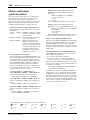
20 Input Channels
01V96i—Reference Manual
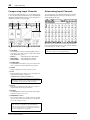
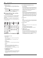
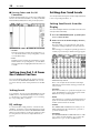
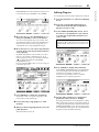
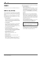
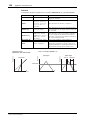
Compressing Input Channels
To set the Input Channel compressors, use the [SEL] buttons
to select the desired Input Channel, then press the DISPLAY
ACCESS [DYNAMICS] button, then press the [F3] button to
display the Dynamics | Comp Edit page.
1 POSITION
Use the Parameter wheel, or the [INC]/[DEC] buttons to
select the position of the compressor within the channel
from the following options:
• PRE EQ....................Immediately before EQ (default)
• PRE FADER ...........Immediately before the fader
• POST FADER ........Immediately after the fader
2 STEREO LINK
This ON/OFF button enables you to pair compressors for
stereo operation even when channels are not paired.
3 CURVE
This area displays the current compressor curve.
4 TYPE
This field indicates the compressor type used by the cur-
rently-selected channel’s compressor
(COMP/EXPAND/COMP (H)/COMP (S)).
5 Meters
These meters indicate the levels of the post-compressor
signals and the amount of gain reduction.
6 ON/OFF
The ON/OFF button turns the currently-selected Input
Channel’s compressor on or off.
7 PARAMETER section
These controls enable you to set the compressor parame-
ters. (See page 149 for more information on the parame-
ters of each compressor type.)
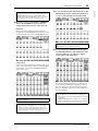
Attenuating Input Channels
To set the attenuator for each Input Channel, press the DIS-
PLAY ACCESS [EQ] button, then press the [F3] button to
display the EQ | In Att page.
Move the cursor to the knob for the desired Input Channel,
then rotate the Parameter wheel to set the amount of attenua-
tion in the range of –96 dB to +12 dB.
Note: You cannot change the Compressor type on this page.
To change the compressor type, recall a program that uses the
desired compressor type from the compressor library.
Tip:
• This function is unavailable for the ST IN Channels.
• You can store the compressor settings in the compressor
library, which features preset programs that can be used
for various applications (see page 80).
3 4 521
76
Tip: You can also set the attenuation amount (in dB) for the cur-
rently-selected channel on the EQ | EQ Edit page.
La pagina sta caricando ...
La pagina sta caricando ...
La pagina sta caricando ...
La pagina sta caricando ...
La pagina sta caricando ...
La pagina sta caricando ...
La pagina sta caricando ...
La pagina sta caricando ...
La pagina sta caricando ...
La pagina sta caricando ...
La pagina sta caricando ...
La pagina sta caricando ...
La pagina sta caricando ...
La pagina sta caricando ...
La pagina sta caricando ...
La pagina sta caricando ...
La pagina sta caricando ...
La pagina sta caricando ...
La pagina sta caricando ...
La pagina sta caricando ...
La pagina sta caricando ...
La pagina sta caricando ...
La pagina sta caricando ...
La pagina sta caricando ...
La pagina sta caricando ...
La pagina sta caricando ...
La pagina sta caricando ...
La pagina sta caricando ...
La pagina sta caricando ...
La pagina sta caricando ...
La pagina sta caricando ...
La pagina sta caricando ...
La pagina sta caricando ...
La pagina sta caricando ...
La pagina sta caricando ...
La pagina sta caricando ...
La pagina sta caricando ...
La pagina sta caricando ...
La pagina sta caricando ...
La pagina sta caricando ...
La pagina sta caricando ...
La pagina sta caricando ...
La pagina sta caricando ...
La pagina sta caricando ...
La pagina sta caricando ...
La pagina sta caricando ...
La pagina sta caricando ...
La pagina sta caricando ...
La pagina sta caricando ...
La pagina sta caricando ...
La pagina sta caricando ...
La pagina sta caricando ...
La pagina sta caricando ...
La pagina sta caricando ...
La pagina sta caricando ...
La pagina sta caricando ...
La pagina sta caricando ...
La pagina sta caricando ...
La pagina sta caricando ...
La pagina sta caricando ...
La pagina sta caricando ...
La pagina sta caricando ...
La pagina sta caricando ...
La pagina sta caricando ...
La pagina sta caricando ...
La pagina sta caricando ...
La pagina sta caricando ...
La pagina sta caricando ...
La pagina sta caricando ...
La pagina sta caricando ...
La pagina sta caricando ...
La pagina sta caricando ...
La pagina sta caricando ...
La pagina sta caricando ...
La pagina sta caricando ...
La pagina sta caricando ...
La pagina sta caricando ...
La pagina sta caricando ...
La pagina sta caricando ...
La pagina sta caricando ...
La pagina sta caricando ...
La pagina sta caricando ...
La pagina sta caricando ...
La pagina sta caricando ...
La pagina sta caricando ...
La pagina sta caricando ...
La pagina sta caricando ...
La pagina sta caricando ...
La pagina sta caricando ...
La pagina sta caricando ...
La pagina sta caricando ...
La pagina sta caricando ...
La pagina sta caricando ...
La pagina sta caricando ...
La pagina sta caricando ...
La pagina sta caricando ...
La pagina sta caricando ...
La pagina sta caricando ...
La pagina sta caricando ...
La pagina sta caricando ...
La pagina sta caricando ...
La pagina sta caricando ...
La pagina sta caricando ...
La pagina sta caricando ...
La pagina sta caricando ...
La pagina sta caricando ...
La pagina sta caricando ...
La pagina sta caricando ...
La pagina sta caricando ...
La pagina sta caricando ...
La pagina sta caricando ...
La pagina sta caricando ...
La pagina sta caricando ...
La pagina sta caricando ...
La pagina sta caricando ...
La pagina sta caricando ...
La pagina sta caricando ...
La pagina sta caricando ...
La pagina sta caricando ...
La pagina sta caricando ...
La pagina sta caricando ...
La pagina sta caricando ...
La pagina sta caricando ...
La pagina sta caricando ...
La pagina sta caricando ...
La pagina sta caricando ...
La pagina sta caricando ...
La pagina sta caricando ...
La pagina sta caricando ...
La pagina sta caricando ...
La pagina sta caricando ...
La pagina sta caricando ...
La pagina sta caricando ...
La pagina sta caricando ...
La pagina sta caricando ...
La pagina sta caricando ...
La pagina sta caricando ...
La pagina sta caricando ...
La pagina sta caricando ...
La pagina sta caricando ...
La pagina sta caricando ...
La pagina sta caricando ...
La pagina sta caricando ...
La pagina sta caricando ...
La pagina sta caricando ...
La pagina sta caricando ...
La pagina sta caricando ...
La pagina sta caricando ...
La pagina sta caricando ...
La pagina sta caricando ...
La pagina sta caricando ...
La pagina sta caricando ...
La pagina sta caricando ...
La pagina sta caricando ...
La pagina sta caricando ...
La pagina sta caricando ...
La pagina sta caricando ...
La pagina sta caricando ...
La pagina sta caricando ...
La pagina sta caricando ...
La pagina sta caricando ...
La pagina sta caricando ...
La pagina sta caricando ...
La pagina sta caricando ...
La pagina sta caricando ...
La pagina sta caricando ...
-
 1
1
-
 2
2
-
 3
3
-
 4
4
-
 5
5
-
 6
6
-
 7
7
-
 8
8
-
 9
9
-
 10
10
-
 11
11
-
 12
12
-
 13
13
-
 14
14
-
 15
15
-
 16
16
-
 17
17
-
 18
18
-
 19
19
-
 20
20
-
 21
21
-
 22
22
-
 23
23
-
 24
24
-
 25
25
-
 26
26
-
 27
27
-
 28
28
-
 29
29
-
 30
30
-
 31
31
-
 32
32
-
 33
33
-
 34
34
-
 35
35
-
 36
36
-
 37
37
-
 38
38
-
 39
39
-
 40
40
-
 41
41
-
 42
42
-
 43
43
-
 44
44
-
 45
45
-
 46
46
-
 47
47
-
 48
48
-
 49
49
-
 50
50
-
 51
51
-
 52
52
-
 53
53
-
 54
54
-
 55
55
-
 56
56
-
 57
57
-
 58
58
-
 59
59
-
 60
60
-
 61
61
-
 62
62
-
 63
63
-
 64
64
-
 65
65
-
 66
66
-
 67
67
-
 68
68
-
 69
69
-
 70
70
-
 71
71
-
 72
72
-
 73
73
-
 74
74
-
 75
75
-
 76
76
-
 77
77
-
 78
78
-
 79
79
-
 80
80
-
 81
81
-
 82
82
-
 83
83
-
 84
84
-
 85
85
-
 86
86
-
 87
87
-
 88
88
-
 89
89
-
 90
90
-
 91
91
-
 92
92
-
 93
93
-
 94
94
-
 95
95
-
 96
96
-
 97
97
-
 98
98
-
 99
99
-
 100
100
-
 101
101
-
 102
102
-
 103
103
-
 104
104
-
 105
105
-
 106
106
-
 107
107
-
 108
108
-
 109
109
-
 110
110
-
 111
111
-
 112
112
-
 113
113
-
 114
114
-
 115
115
-
 116
116
-
 117
117
-
 118
118
-
 119
119
-
 120
120
-
 121
121
-
 122
122
-
 123
123
-
 124
124
-
 125
125
-
 126
126
-
 127
127
-
 128
128
-
 129
129
-
 130
130
-
 131
131
-
 132
132
-
 133
133
-
 134
134
-
 135
135
-
 136
136
-
 137
137
-
 138
138
-
 139
139
-
 140
140
-
 141
141
-
 142
142
-
 143
143
-
 144
144
-
 145
145
-
 146
146
-
 147
147
-
 148
148
-
 149
149
-
 150
150
-
 151
151
-
 152
152
-
 153
153
-
 154
154
-
 155
155
-
 156
156
-
 157
157
-
 158
158
-
 159
159
-
 160
160
-
 161
161
-
 162
162
-
 163
163
-
 164
164
-
 165
165
-
 166
166
-
 167
167
-
 168
168
-
 169
169
-
 170
170
-
 171
171
-
 172
172
-
 173
173
-
 174
174
-
 175
175
-
 176
176
-
 177
177
-
 178
178
-
 179
179
-
 180
180
-
 181
181
-
 182
182
-
 183
183
-
 184
184
-
 185
185
-
 186
186


Yamaha 01V96i Manuale utente
- Categoria
- Apparecchiature musicali supplementari
- Tipo
- Manuale utente
- Questo manuale è adatto anche per
in altre lingue
- English: Yamaha 01V96i User manual
- français: Yamaha 01V96i Manuel utilisateur
- español: Yamaha 01V96i Manual de usuario
Documenti correlati
-
Yamaha V96i Manuale del proprietario
-
Yamaha 01V96i Guida utente
-
-
-
-
-
-
-
Yamaha DM2000 Manuale del proprietario
-
Altri documenti
-
Marantz PMD-706 Guida utente
-
PROEL AMP120XL Manuale utente
-
Sharp CP-LS100 Manuale utente
-
Alesis BASSFIRE 60 Manuale utente
-
Focusrite Platinum OctoPre Guida utente
-
Sigma R500T EOX Remote 500 Smart Control Center Manuale utente
-
Sigma EOX REMOTE 500 E-Bike Manuale utente
-
Sigma EOX View 1300 Guida utente
-
Brigade MDR-304-XXX (2875)(2876)(2877)(3478)(3480) Manuale utente
-
Metrix OX530 Manuale del proprietario