CAUTION
1 To assure the finest performance, please read this manual
carefully. Keep it in a safe place for future reference.
2 Install this sound system in a well ventilated, cool, dry, clean
place with at least 5 cm on the top, 5 cm on the left and right,
and 5 cm at the back of AVR-S80, and 20 cm on the top, 10 cm
on the left and right, and 10 cm at the back of SW-S80 — away
from direct sunlight, heat sources, vibration, dust, moisture, and/
or cold.
3 Locate this system away from other electrical appliances,
motors, or transformers to avoid humming sounds. To prevent
fire or electrical shock, do not place this system where it may get
exposed to dripping or splashing, and never put any objects filled
with liquids, such as vases, on the top of the system.
4 Do not expose this system to sudden temperature changes from
cold to hot, and do not locate this system in a environment with
high humidity (i.e. a room with a humidifier) to prevent
condensation inside this system, which may cause an electrical
shock, fire, damage to this system, and/or personal injury.
5 Avoid installing this system in a place where foreign objects and
liquid might fall. It might cause a fire, damage to this system
and/or personal injury. Do not place the following objects on this
system:
– Other components, as they may cause damage and/or
discoloration on the surface of this system.
– Burning objects (i.e. candles), as they may cause fire, damage
to this system, and/or personal injury.
– Containers with liquid in them, as they may cause electrical
shock to the user and/or damage to this system.
6 Do not cover this system with a newspaper, tablecloth, curtain,
etc. in order not to obstruct heat radiation. If the temperature
inside this system rises, it may cause fire, damage to this system,
and/or personal injury.
7 Do not plug in this system to a wall outlet until all connections
are complete.
8 Do not operate this system upside-down. It may overheat,
possibly causing damage.
9 Do not use force on switches, knobs and/or cords.
10 When disconnecting the power cord from the wall outlet, grasp
the plug; do not pull the cord.
11 Do not clean this system with chemical solvents; this might
damage the finish. Use a clean, dry cloth.
12 Only voltage specified on this system must be used. Using this
system with a higher voltage than specified is dangerous and
may cause fire, damage to this system, and/or personal injury.
YAMAHA will not be held responsible for any damage resulting
from use of this system with a voltage other than specified.
13 To prevent damage by lightning, disconnect the power cord from
the wall outlet during an electrical storm.
14 Take care of this system so that no foreign objects and/or liquid
drops inside this system.
15 Do not attempt to modify or fix this system. Contact qualified
YAMAHA service personnel when any service is needed. The
cabinet should never be opened for any reasons.
16 When µanning to use this system for long periods of time (i.e.
vacation), disconnect the AC power plug from the wall outlet.
17
Be sure to read the “TROUBLESHOOTING” section on common
operating errors before concluding that this system is faulty.
18 Before moving this system, press STANDBY/ON to set this
system in the standby mode, and disconnect the AC power plug
from the wall outlet.
CAUTION: READ THIS BEFORE OPERATING YOUR SYSTEM.
This system is not disconnected from the AC power source as long
as it is connected to the wall outlet, even if this system itself is
turned off. This state is called the standby mode. In this state, this
system is designed to consume a very small quantity of power.
IMPORTANT
Please record the serial number of this system in the space below.
MODEL:
Serial No.:
The serial number is located on the bottom of AVR-S80 and the
rear of SW-S80.
Retain this Owner’s Manual in a safe place for future reference.
YAMAHA and the Electronic Industries Association’s Consumer
Electronics Group want you to get the most out of your equipment by
playing it at a safe level. One that lets the sound come through loud
and clear without annoying blaring or distortion – and, most
importantly, without affecting your sensitive hearing.
Since hearing damage from loud sounds is often
undetectable until it is too late, YAMAHA and the
Electronic Industries Association’s Consumer
Electronics Group recommend you to avoid prolonged
exposure from excessive volume levels.
We Want You Listening For A Lifetime
■ For U.K. customers
If the socket outlets in the home are not suitable for the plug supplied
with this appliance, it should be cut off and an appropriate 3 pin plug
fitted. For details, refer to the instructions described below.
Note
• The plug severed from the mains lead must be destroyed, as a plug
with bared flexible cord is hazardous if engaged in a live socket
outlet.
■ Special Instructions for U.K. Model
IMPORTANT
THE WIRES IN MAINS LEAD ARE COLOURED IN
ACCORDANCE WITH THE FOLLOWING CODE:
Blue: NEUTRAL
Brown: LIVE
As the colours of the wires in the mains lead of this apparatus
may not correspond with the coloured markings identifying the
terminals in your plug, proceed as follows:
The wire which is coloured BLUE must be connected to the
terminal which is marked with the letter N or coloured BLACK.
The wire which is coloured BROWN must be connected to the
terminal which is marked with the letter L or coloured RED.
Making sure that neither core is connected to the earth terminal of
the three pin plug.
The name plate is located on the bottom of AVR-S80.
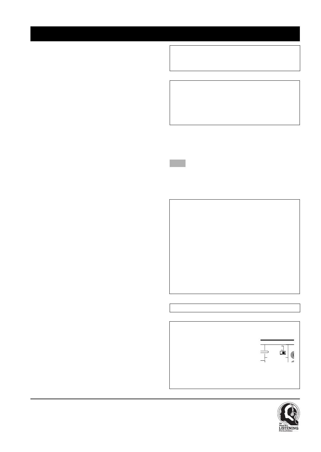
FREQUENCY STEP switch
(China, Korean and General models only)
Because the interstation frequency spacing
differs in different areas, set the
FREQUENCY STEP switch (locating at the
rear of AVR-S80) according to the frequency
spacing in your area.
North, Central and South America: 100 kHz/10 kHz
Other area: 50 kHz/9 kHz
Before setting this switch, disconnect the AC power plug of this
system from the AC outlet.
FREQUENCY STEP
50
K
Hz
100
K
Hz
FM
9
K
Hz
10
K
Hz
AM
102_S80_Cau(UB) (5.30)a 02.5.30, 1:15 PM4


