Denon AVR-1603 Manuale utente
- Categoria
- Ricevitori AV
- Tipo
- Manuale utente

FOR ENGLISH READERS PAGE 00, 02 ~ PAGE 029, 192
FÜR DEUTSCHE LESER SEITE 02, 30 ~ SEITE 056, 192
POUR LES LECTEURS FRANCAIS PAGE 02, 57 ~ PAGE 083, 192
PER IL LETTORE ITALIANO PAGINA 02, 84 ~ PAGINA 110, 192
PARA LECTORES DE ESPAÑOL PAGINA 2, 111 ~ PAGINA 137, 192
VOOR NEDERLANDSTALIGE LEZERS PAGINA 2, 138 ~ PAGINA 164, 192
FOR SVENSKA LÄSARE SIDA 2, 165 ~ SIDA 192
AV SURROUND RECEIVER
AVR
-
1603
OPERATING INSTRUCTIONS
BEDIENUNGSANLEITUNG
MODE D’EMPLOI
ISTRUZIONI PER L’USO
INSTRUCCIONES DE OPERACION
GEBRUIKSAANWIJZING
BRUKSANVISNING

2
NOTE ON USE / HINWEISE ZUM GEBRAUCH
OBSERVATIONS RELATIVES A L’UTILISATION / NOTE SULL’USO
NOTAS SOBRE EL USO / ALVORENS TE GEBRUIKEN / OBSERVERA
• Avoid high temperatures.
Allow for sufficient heat dispersion
when installed on a rack.
• Vermeiden Sie hohe Temperaturen.
Beachten Sie, daß eine ausreichend
Luftzirkulation gewährleistet wird, wenn
das Gerät auf ein Regal gestellt wird.
• Eviter des températures élevées
Tenir compte d’une dispersion de
chaleur suffisante lors de l’installation
sur une étagère.
• Evitate di esporre l’unità a temperature
alte.
Assicuratevi che ci sia un’adeguata
dispersione del calore quando installate
l’unità in un mobile per componenti
audio.
• Evite altas temperaturas
Permite la suficiente dispersión del calor
cuando está instalado en la consola.
• Vermijd hoge temperaturen.
Zorg voor een degelijk hitteafvoer indien
het apparaat op een rek wordt geplaatst.
• Undvik höga temperaturer.
Se till att det finns möjlighet till god
värmeavledning vid montering i ett rack.
• Handle the power cord carefully.
Hold the plug when unplugging the
cord.
• Gehen Sie vorsichtig mit dem Netzkabel
um.
Halten Sie das Kabel am Stecker, wenn
Sie den Stecker herausziehen.
• Manipuler le cordon d’alimentation avec
précaution.
Tenir la prise lors du débranchement du
cordon.
• Manneggiate il filo di alimentazione con
cura.
Agite per la spina quando scollegate il
cavo dalla presa.
• Maneje el cordón de energía con
cuidado.
Sostenga el enchufe cuando
desconecte el cordón de energía.
• Hanteer het netsnoer voorzichtig.
Houd het snoer bij de stekker vast
wanneer deze moet worden aan- of
losgekoppeld.
• Hantera nätkabeln varsamt.
Håll i kabeln när den kopplas från el-
uttaget.
• Keep the set free from moisture, water,
and dust.
• Halten Sie das Gerät von Feuchtigkeit,
Wasser und Staub fern.
• Protéger l’appareil contre l’humidité,
l’eau et lapoussière.
• Tenete l’unità lontana dall’umidità,
dall’acqua e dalla polvere.
• Mantenga el equipo libre de humedad,
agua y polvo.
• Laat geen vochtigheid, water of stof in
het apparaat binnendringen.
• Utsätt inte apparaten för fukt, vatten
och damm.
• Unplug the power cord when not using
the set for long periods of time.
• Wenn das Gerät eine längere Zeit nicht
verwendet werden soll, trennen Sie das
Netzkabel vom Netzstecker.
• Débrancher le cordon d’alimentation
lorsque l’appareil n’est pas utilisé
pendant de longues périodes.
• Disinnestate il filo di alimentazione
quando avete l’intenzione di non usare il
filo di alimentazione per un lungo
periodo di tempo.
• Desconecte el cordón de energía
cuando no utilice el equipo por mucho
tiempo.
• Neem altijd het netsnoer uit het
stopkontakt wanneer het apparaat
gedurende een lange periode niet wordt
gebruikt.
• Koppla ur nätkabeln om apparaten inte
kommer att användas i lång tid.
• Do not obstruct the ventilation holes.
• Die Belüftungsöffnungen dürfen nicht
verdeckt werden.
• Ne pas obstruer les trous d’aération.
• Non coprite i fori di ventilazione.
• No obstruya los orificios de ventilación.
• De ventilatieopeningen mogen niet
worden beblokkeerd.
• Täpp inte till ventilationsöppningarna.
* (For sets with ventilation holes)
• Do not let foreign objects in the set.
• Keine fremden Gegenstände in das
Gerät kommen lassen.
• Ne pas laisser des objets étrangers dans
l’appareil.
• E’ importante che nessun oggetto è
inserito all’interno dell’unità.
• No deje objetos extraños dentro del
equipo.
• Laat geen vreemde voorwerpen in dit
apparaat vallen.
• Se till att främmande föremål inte
tränger in i apparaten.
• Do not let insecticides, benzene, and
thinner come in contact with the set.
• Lassen Sie das Gerät nicht mit
Insektiziden, Benzin oder
Verdünnungsmitteln in Berührung
kommen.
• Ne pas mettre en contact des
insecticides, du benzène et un diluant
avec l’appareil.
• Assicuratevvi che l’unità non venga in
contatto con insetticidi, benzolo o
solventi.
• No permita el contacto de insecticidas,
gasolina y diluyentes con el equipo.
• Laat geen insektenverdelgende
middelen, benzine of verfverdunner met
dit apparaat in kontakt komen.
• Se till att inte insektsmedel på
spraybruk, bensen och thinner kommer i
kontakt med apparatens hölje.
• Never disassemble or modify the set in
any way.
• Versuchen Sie niemals das Gerät
auseinander zu nehmen oder auf
jegliche Art zu verändern.
• Ne jamais démonter ou modifier
l’appareil d’une manière ou d’une autre.
• Non smontate mai, nè modificate l’unità
in nessun modo.
• Nunca desarme o modifique el equipo
de ninguna manera.
• Nooit dit apparaat demonteren of op
andere wijze modifiëren.
• Ta inte isär apparaten och försök inte
bygga om den.
ENGLISH DEUTSCH FRANCAIS ITALIANO ESPAÑOL NEDERLANDS SVENSKA
The lightning flash with arrowhead symbol, within an equilateral
triangle, is intended to alert the user to the presence of uninsulated
“dangerous voltage” within the product’s enclosure that may be of
sufficient magnitude to constitute a risk of electric shock to persons.
The exclamation point within an equilateral triangle is intended to alert
the user to the presence of important operating and maintenance
(servicing) instructions in the literature accompanying the appliance.
WARNING:
TO REDUCE THE RISK OF FIRE OR ELECTRIC SHOCK, DO NOT
EXPOSE THIS APPLIANCE TO RAIN OR MOISTURE.
CAUTION
RISK OF ELECTRIC SHOCK
DO NOT OPEN
CAUTION:
TO REDUCE THE RISK OF ELECTRIC
SHOCK, DO NOT REMOVE COVER (OR
BACK). NO USER-SERVICEABLE PARTS
INSIDE. REFER SERVICING TO QUALIFIED
SERVICE PERSONNEL.
• DECLARATION OF CONFORMITY
We declare under our sole responsibility that this
product, to which this declaration relates, is in
conformity with the following standards:
EN60065, EN55013, EN55020, EN61000-3-2 and
EN61000-3-3.
Following the provisions of 73/23/EEC, 89/336/EEC and
93/68/EEC Directive.
• ÜBEREINSTIMMUNGSERKLÄRUNG
Wir erklären unter unserer Verantwortung, daß dieses
Produkt, auf das sich diese Erklärung bezieht, den
folgenden Standards entspricht:
EN60065, EN55013, EN55020, EN61000-3-2 und
EN61000-3-3.
Entspricht den Verordnungen der Direktive 73/23/EEC,
89/336/EEC und 93/68/EEC.
• DECLARATION DE CONFORMITE
Nous déclarons sous notre seule responsabilité que
l’appareil, auquel se réfère cette déclaration, est
conforme aux standards suivants:
EN60065, EN55013, EN55020, EN61000-3-2 et
EN61000-3-3.
D’après les dispositions de la Directive 73/23/EEC,
89/336/EEC et 93/68/EEC.
• DICHIARAZIONE DI CONFORMITÀ
Dichiariamo con piena responsabilità che questo
prodotto, al quale la nostra dichiarazione si riferisce, è
conforme alle seguenti normative:
EN60065, EN55013, EN55020, EN61000-3-2 e
EN61000-3-3.
In conformità con le condizioni delle direttive 73/23/EEC,
89/336/EEC e 93/68/EEC.
QUESTO PRODOTTO E’ CONFORME
AL D.M. 28/08/95 N. 548
• DECLARACIÓN DE CONFORMIDAD
Declaramos bajo nuestra exclusiva responsabilidad que
este producto al que hace referencia esta declaración,
está conforme con los siguientes estándares:
EN60065, EN55013, EN55020, EN61000-3-2 y
EN61000-3-3.
Siguiendo las provisiones de las Directivas 73/23/EEC,
89/336/EEC y 93/68/EEC.
• EENVORMIGHEIDSVERKLARING
Wij verklaren uitsluitend op onze verantwoordelijkheid
dat dit produkt, waarop deze verklaring betrekking
heeft, in overeenstemming is met de volgende normen:
EN60065, EN55013, EN55020, EN61000-3-2 en
EN61000-3-3.
Volgens de bepalingen van de Richtlijnen 73/23/EEC,
89/336/EEC en 93/68/EEC.
• ÖVERENSSTÄMMELSESINTYG
Härmed intygas helt på eget ansvar att denna produkt,
vilken detta intyg avser, uppfyller följande standarder:
EN60065, EN55013, EN55020, EN61000-3-2 och
EN61000-3-3.
Enligt stadgarna i direktiv 73/23/EEC, 89/336/EEC och
93/68/EEC.
CAUTION
• The ventilation should not be impeded by covering the ventilation openings with items, such as newspapers, table-cloths,
curtains, etc.
• No naked flame sources, such as lighted candles, should be placed on the apparatus.
• Please be care the environmental aspects of battery disposal.
• The apparatus shall not be exposed to dripping or splashing for use.
• No objects filled with liquids, such as vases, shall be placed on the apparatus.

3
ENGLISH
2 We greatly appreciate your purchase of the AVR-1603.
2 To be sure you take maximum advantage of all the features AVR-1603 has to offer, read these
instructions carefully and use the set properly. Be sure to keep this manual for future reference
should any questions or problems arise.
“SERIAL NO.
PLEASE RECORD UNIT SERIAL NUMBER ATTACHED TO THE REAR OF
THE CABINET FOR FUTURE REFERENCE”
2 INTRODUCTION
Thank you for choosing the DENON A/V Surround receiver. This remarkable component has been engineered to
provide superb surround sound listening with home theater sources such as DVD, as well as providing outstanding
high fidelity reproduction of your favorite music sources.
As this product is provided with an immense array of features, we recommend that before you begin hookup and
operation that you review the contents of this manual before proceeding.
TABLE OF CONTENTS
2 ACCESSORIES
Check that the following parts are included in addition to the main unit:
er t y
z
Before Using .......................................................3
x
Cautions on Installation .......................................3
c
Cautions on Handling ..........................................3
v
Features ..............................................................3
b
Part Names and Functions ..................................4
n
Read this First .....................................................5
m
Setting up the Speaker Systems.........................5
,
Connections..................................................5 ~ 8
.
Using the Remote Control Unit...........................9
⁄0
Setting up the system ................................9 ~ 12
⁄1
Remote Control Unit.................................13 ~ 15
⁄2
Operation ..................................................15 ~ 18
⁄3
Surround ...................................................18 ~ 20
⁄4
DSP Surround Simulation .........................21 ~ 23
⁄
5
Listening to the Radio...............................23 ~ 26
⁄6
Last Function Memory ......................................26
⁄7
Initialization of the Microprocessor ...................26
⁄8
Additional Information .................................27, 28
⁄9
Troubleshooting ................................................28
¤0
Specifications ....................................................29
List of Preset Codes.....................................192 ~ 194
q Operating instructions……………………………1
w Service station list ………………………………1
e Remote control unit (RC-920) …………………1
r R6P/AA batteries ………………………………2
t AM loop antenna …………………………………1
y FM indoor antenna ………………………………1
1
BEFORE USING
Pay attention to the following before using this unit:
• Moving the set
To prevent short circuits or damaged wires in the
connection cords, always unplug the power cord and
disconnect the connection cords between all other
audio components when moving the set.
• Before turning the power operation switch on
Check once again that all connections are proper and
that there are not problems with the connection cords.
Always set the power operation switch to the
standby position before connecting and disconnecting
connection cords.
• Store this instructions in a safe place.
After reading, store this instructions along with the
warranty in a safe place.
• Note that the illustrations in this instructions may
differ from the actual set for explanation purposes.
• V. AUX terminal
The AVR-1603's front
panel is equipped with a
V. AUX terminal. Remove
the cap covering the
terminal when you want
to use it.
Noise or disturbance of the picture may be generated
if this unit or any other electronic equipment using
microprocessors is used near a tuner or TV.
If this happens, take the following steps:
• Install this unit as far as possible from the tuner or
TV.
• Set the antenna wires from the tuner or TV away from
this unit’s power cord and input/output connection
cords.
• Noise or disturbance tends to occur particularly when
using indoor antennas or 300 Ω/ohms feeder wires.
We recommend using outdoor antennas and 75
Ω/ohms coaxial cables.
For heat dispersal, leave at least 10 cm of space
between the top, back and sides of this unit and the
wall or other components.
• Switching the input function when input jacks are
not connected
A clicking noise may be produced if the input function
is switched when nothing is connected to the input
jacks. If this happens, either turn down the MASTER
VOLUME control or connect components to the input
jacks.
• Muting of PRE OUT jack, HEADPHONE jack and
SPEAKER terminals
The PRE OUT jack, HEADPHONE jack and
SPEAKER terminals include a muting circuit.
Because of this, the output signals are greatly
reduced for several seconds after the power
operation switch is turned on or input function,
surround mode or any other set-up is changed.
If the volume is turned up during this time, the output
will be very high after the muting circuit stops
functioning. Always wait until the muting circuit turns
off before adjusting the volume.
• Whenever the power operation switch is in the
£ OFF or STANDBY state, the apparatus is still
connected on some AC line voltages.
Please be sure to unplug the cord when you leave
home for, say, a vacation.
1. Dolby Pro Logic II decoder
Dolby Pro Logic II is a new format for playing
multichannel audio signals that offers
improvements over conventional Dolby Pro Logic.
It can be used to decode not only sources recorded
in Dolby Surround but also regular stereo sources
into five channels (front left/right, center and
surround left/right). In addition, various parameters
can be set according to the type of source and the
contents, so you can adjust the sound field with
greater precision.
2. Dolby Digital decoder
Dolby Digital, a digital discrete system in which the
different channels are completely independent,
recreates “three-dimensional” sound fields (sounds
with a sense of distance, movement and position)
with no crosstalk between channels for greater
reality. In addition, the 5 channels (excluding the 0.1
channel for low frequency effects) have a playback
range extending to 20 kHz, the same as the range
of CDs, thus resulting in clearer, more richly
expressive sound.
3. DTS (Digital Theater Systems) decoder
DTS provides up to 5.1 channels of wide-range, high
fidelity surround sound, from sources such as laser
disc, DVD and specially-encoded music discs.
4. High performance DSP simulates 7 sound fields
Playback is possible in 7 surround modes: 5-channel
Stereo, Mono Movie, Rock Arena, Jazz Club, Video
Game, Matrix and Virtual. You can enjoy a variety of
sound effects for different movie scenes and
program sources even with stereo sources not in
Dolby Surround.
5. Personal Memory Plus function
Personal Memory Plus is an advanced version of
Personal Memory. With Personal Memory Plus, the
set automatically memorizes the surround mode,
channel volume, surround parameters, etc., for each
of the separate input sources.
6. Remote control unit with pre-memory function
This unit comes with a remote control unit equipped
with a pre-memory function. The remote control
command codes for DENON remote controllable AV
components as well as for LD players, video decks,
TVs, etc., of other major manufacturers are prestored
in the memory.
7. EXT. IN jack
This unit is equipped with EXT. IN jacks for use with
audio formats of the future.
2
CAUTIONS ON INSTALLATION
3
CAUTIONS ON HANDLING
4
FEATURES
10 cm or more
10 cm or more
wall

ENGLISH
4
5
PART NAMES AND FUNCTIONS
Front Panel
• For details on the functions of these parts, refer to the pages given in parentheses ( ).
q w te ur
y i!3!0
@0@1
@2@3@4@5
@6
@7@8@9
!1 !2 !4 !5 !6o
!7!9 !8#0
q
Power operation switch ......................(10, 15, 23)
w
Headphones jack (PHONES) ...........................(17)
e
INPUT MODE button ..........................(16, 17, 19)
r
SPEAKER A/B buttons ..............................(15, 26)
t
TONE DEFEAT button.....................................(17)
y
ANALOG button ........................................(16, 17)
u
DOLBY/DTS SURROUND button..............(18. 19)
i
5CH STEREO button .......................................(20)
o
DIRECT/STEREO button .................................(20)
!0
TUNING UP/DOWN buttons ...........................(24)
!1
RDS button................................................(25, 26)
!2
V. AUX terminals ...........................................(3, 7)
!3
SURROUND MODE button.......................(16, 22)
!4
SURROUND PARAMETER button ............(19, 22)
!5
SELECT knob ....................................(16 ~ 19, 22)
!6
TONE CONTROL button .................................(16)
!7
CH VOL button................................................(18)
!8
MASTER VOLUME control .............................(16)
!9
RT button ........................................................(26)
@0
PTY button ......................................................(25)
@1
Master volume indicator (VOLUME LEVEL)....(16)
@2
Display
@3
Preset station select buttons..................(23 ~ 26)
@4
BAND button...................................................(24)
@5
EXT. IN button...........................................(16, 17)
@6
SIGNAL indicators ...........................................(16)
@7
INPUT mode indicators ...................................(16)
@8
Remote control sensor (REMOTE SENSOR) ....(9)
@9
Power operation indicator (ON/STANDBY)
#0
INPUT SELECTOR knob .......(16, 18, 19, 24 ~ 26)
Remote control unit
• For details on the functions of these parts, refer to the pages given in parentheses ( ).
LED (indicator).................(13, 15)
SURROUND
button..................(16, 18, 19, 21)
Test tone button ...................(18)
Input source selector buttons
............(13 ~16, 18, 19, 24 ~ 26)
Remote control signal
transmitter ..............................(9)
POWER buttons ...........(13 ~ 15)
Master volume control
buttons..................................(16)
MUTING button ....................(17)
Tuner system/
buttons .............(13, 14, 24 ~ 26)
SURROUND PARAMETER
button .....................(14, 19 ~ 22)
Mode select
switches ...................(9, 13 ~ 15)
SYSTEM SETUP/
SETUP button .............(9, 12, 14)
STATUS/DISPLAY button
..(14, 17)
Cursor buttons
...................(9 ~ 12, 14, 18 ~ 22)
DIMMER button....................(17)
CH SELECT (channel select)/
ENTER button ..............(9, 14, 18)
VIDEO SELECT button..........(17)
SPEAKER select button ........(15)
RETURN button ....................(14)
INPUT MODE select
buttons......................(16, 17, 19)
System buttons...............(13, 14)
NOTE:
• The shaded buttons do not function with
the AVR-1603. (Nothing happens when they are
pressed.)

R
INTPUTOUTPUT
LRL
R
L
R
L
R
L
R
L
R
L
L
R
Step 3 (page 9 to 12)
Finally, setting up the system.
Step 2 (page 9)
Next, insert the batteries into the remote control unit.
ENGLISH
5
2 Speaker system layout
Basic system layout
• The following is an example of the basic layout for a system consisting of six speaker systems and a television
monitor:
Subwoofer
Center speaker system
Front speaker systems
Set these at the sides of the TV or
screen with their front surfaces as
flush with the front of the screen as
possible.
Surround speaker systems
6
READ THIS FIRST
This A / V surround Receiver must be setup before use. Following these steps.
Step 1 (page 5 to 8)
Choose the location to setup the speakers and connecting the components.
7
SETTING UP THE SPEAKER SYSTEMS
•
Do not plug in the power cord until all connections
have been completed.
•
Be sure to connect the left and right channels
properly (left with left, right with right).
•
Insert the plugs securely. Incomplete connections
will result in the generation of noise.
•
Use the AC OUTLET for audio equipment only. Do
not use them for hair driers, etc.
• Note that binding pin plug cords together with power
cords or placing them near a power transformer
will result in generating hum or other noise.
• Noise or humming may be generated if a connected
audio equipment is used independently without
turning the power of this unit on. If this happens,
turn on the power of this unit.
Connecting the audio components (1)
Decoders with 6-channel
analog outputs, etc.
Connecting a tape deck
Connections for recording:
Connect the tape deck’s recording input jacks (LINE IN or REC) to this unit’s tape
recording (OUT) jacks using pin plug cords.
Connections for playback:
Connect the tape deck’s playback output jacks (LINE OUT or PB) to this unit’s tape
playback (IN) jacks using pin plug cords.
8
CONNECTIONS
Tape deck or CD recorder
AC 230 V, 50 Hz
AC CORD
Connecting the AC OUTLET
AC OUTLET
• SWITCHED (capacity – 100 W)
The power to these outlets is turned on and off in conjunction with the POWER
switch on the main unit, and when the power is switched between on and standby
from the remote control unit.
No power is supplied from these outlets when this unit’s power is at standby. Never
connect equipment whose capacity is above 100 W.
NOTE:
Only use the AC OUTLET for audio equipment. Never use them for hair driers, TVs or
other electrical appliances.
• Analog recording of signals input to the AVR-1603 in digital format is not possible. To record in analog, also
connect the analog signals of the player to the AVR-1603’s analog input terminals.
• The AVR-1603’s OPTICAL OUT terminal is an optical digital output terminal for connection of a CD
recorder, MD recorder or other digital recording device. Use it for digital recording.
AUDIO IN
AUDIO OUT
FRONT
SUBWOOFER
CENTER
SURROUND
AUDIO OUT

OPTICALCOAXIAL
R
L
DIGITAL AUDIODIGITAL AUDIO
RL
R
L
OUTPUT
OPTICAL
DIGITAL AUDIODIGITAL AUDIO
AUDIO OUT
OUTPUT
DIGITAL OUT
DIGITAL OUT
DIGITAL OUT
DIGITAL IN
OUTPUT
B
INPUT
ENGLISH
6
ROUT
VIDEO
OUT
L
AUDIO
OUT
DIGITAL
ROUT
VIDEO
OPTICAL
OUT
L
AUDIO
OUT
DIGITAL
R OUT IN
AUDIO
VIDEO
OUT IN
LRL
R
L
R
L
OPT.-1
R
L
R
L
R
L
L
R
L
R
R
L
IN
VIDEO
B
OPTICAL
B
Connecting the video equipments
TV or DBS tuner
DVD player or video disc player (VDP)
Monitor TV
MONITOR OUT
• Connect the TV’s video input
jack (VIDEO INPUT) to the
MONITOR OUT jack
using a 75 Ω/ohms video
coaxial pin plug cord.
VIDEO
NOTE:
Connection of the video disc Player Equipped with Dolby
Digital RF (AC-3RF) Output Jack.
• Please use a commercially available adaptor when
connecting the Dolby Digital RF (AC-3RF) output jack of
the video disc player to the digital input jack.
Please refer to the instruction manual of the adapter
when making connections.
Connecting a DVD player or a video disc player VDP
• Connect the DVD player’s (video disc player’s) video output jack (VIDEO
OUTPUT) to the (yellow) DVD/VDP IN jack using a 75 Ω/ohms
video coaxial pin plug cord.
• Connect the DVD player’s (video disc player’s) analog audio output jacks
(ANALOG AUDIO OUTPUT) to the DVD/VDP IN jacks using pin
plug cords.
• For better sound quality, we recommend using the DVD player with
digital rather than analog connections.
DVD players and VDP can also be connected to the VCR terminals.
AUDIO
VIDEO
Connecting a video decks
Connecting a TV/DBS tuner
TV/DBS
• Connect the TV’s or DBS tuner’s video output jack (VIDEO OUTPUT) to the
(yellow) TV/DBS IN jack using a 75 Ω/ohms video coaxial pin plug cord.
• Connect the TV’s or DBS tuner’s audio output jacks (AUDIO OUTPUT) to the
TV/DBS IN jacks using pin plug cords.
AUDIO
VIDEO
VIDEO OUT
AUDIO OUT
AUDIO IN
VIDEO IN
AUDIO OUT
VIDEO OUT
VIDEO OUT
AUDIO OUT
DIGITAL OUT
DIGITAL OUT
Video input/output connections:
• Connect the video deck’s video output jack (VIDEO OUT) to the (yellow) VCR IN jack, and the video deck’s video input
jack (VIDEO IN) to the (yellow) VCR OUT jack using 75zΩ/ohms video coaxial pin plug cords.
Connecting the audio output jacks:
• Connect the video deck’s audio output jacks (AUDIO OUT) to the VCR IN jacks, and the video deck’s audio input jacks
(AUDIO IN) to the VCR OUT jacks using pin plug cords.
AUDIO
AUDIO
VIDEO
VIDEO
Video deck
VIDEO IN
CD player
Connecting a CD player
Connect the CD player’s analog output
jacks (ANALOG OUTPUT) to this unit’s CD
jacks using pin plug cords.
CD recorder, MD recorder or other component
equipped with digital input/output jacks
DIGITAL jacks
Use these for connections to audio equipment with digital output.
Refer to page 12 for instructions on setting this terminal.
• Use 75 Ω/ohms cable pin cords (sold separately) for coaxial
connections.
• Use optical cables (sold separately) for optical connections,
removing the cap before connecting.
CD player or other component
equipped with digital output
jacks
Connecting the audio components (2)

ENGLISH
7
To connect the video signal, connect using a 75 Ω/ohms video signal cable cord. Using an improper cable can
result in a drop in sound quality.
R VIDEO OUTOPTICALL
R VIDEO OUTL
OUTPUT
OUTPUT
LINE OUT
DIGITAL OUT
VIDEO OUT
VIDEO OUT
LINE OUT
L
R
L
R
L
R
Connecting a Video game equipment
• Connect the Video game equipment’s output jacks
to this unit’s V. AUX INPUT lacks.
Connecting a Video camera equipment
• Connect the Video camera equipment’s output
jacks to this unit’s V. AUX INPUT lacks.
Video camera
Video game
The V. AUX terminal is covered with a cap.
Remove this cap in order to use the terminal. (See
page 3 for instructions on removing the cap.)
Connecting a video component equipped with S-Video jacks
• When making connections, also refer to the operating instructions of the other components.
• A note on the S input jacks
The input selectors for the S inputs and pin jack inputs work in conjunction with each other.
• Precaution when using S-jacks
This unit’s S-jacks (input and output) and video pin jacks (input and output) have independent circuit structures, so that video
signals input from the S-jacks are only output from the S-jack outputs and video signals input from the pin jacks are only output
from the pin jack outputs.
When connecting this unit with equipment that is equipped with S-jacks, keep the above point in mind and make connections
according to the equipment’s instruction manuals.
IN
S-VIDEO
OUT
S-VIDEO
OUT
S-VIDEO
OUT IN
S-VIDEO
VIDEO IN
VIDEO OUT
VIDEO IN
VIDEO OUT
VIDEO OUT
B
B
DVD player, VDP, etc.
Connecting a monitor TV
Monitor TV
Connecting a TV/DBS tuner
•
Connect the TV’s or DBS tuner’s S video output jack
(S-VIDEO OUTPUT) to the TV/DBS IN jack
using an S jack connection cord.
S-VIDEO
TV or satellite broadcast tuner
Video deck
Connecting the video decks
• Connect the video deck’s S output jack (S-OUT) to the VCR IN
jack and the video deck’s S input jack (S-IN) to the VCR OUT
jack using S jack connection cords.
S-VIDEO
S-VIDEO
Connecting a DVD player or video disc player (VDP)
DVD/VDP
• Connect the DVD player’s or video disc player’s S-
Video output jack to the S-VIDEO DVD/VDP IN jack
using an S-Video connection cord.
MONITOR OUT
• Connect the TV’s or DBS tuner's S video
input (S-VIDEO INPUT) to the
MONITOR OUT jack using a S jack
connection cord.
S-VIDEO
1
4
2
3
Connecting the antenna terminals
DIRECTION OF
BROADCASTING
STATION
FM ANTENNA
75 Ω/ohms
COAXIAL
CABLE
FM INDOOR ANTENNA
(An Accessory)
AM LOOP
ANTENNA
(An Accessory)
AM OUTDOOR
ANTENNA
GROUND
NOTES:
•Do not connect two FM antennas simultaneously.
•Even if an external AM antenna is used, do not
disconnect the AM loop antenna.
•Make sure AM loop antenna lead terminals do
not touch metal parts of the panel.
Connection of AM antennas
1. Push the lever.
2. Insert the
conductor.
3. Return the lever.
AM loop antenna assembly
Connect to the AM
antenna terminals.
Bend in the reverse
direction.
Remove the vinyl tie
and take out the
connection line.
a. With the antenna
on top any stable
surface.
b. With the antenna
attached to a wall.
Installation hole Mount on wall, etc.
Mount

ENGLISH
8
Speaker system connections
• Connect the speaker terminals with the speakers
making sure that like polarities are matched (< with
<, > with >). Mismatching of polarities will result
in weak central sound, unclear orientation of the
various instruments, and the sense of direction of the
stereo being impaired.
• When making connections, take care that none of
the individual conductors of the speaker cord come
in contact with adjacent terminals, with other speaker
cord conductors, or with the rear panel.
Speaker Impedance
• When speaker systems A and B are use separately,
speakers with an impedance of 6 to 16 Ω/ohms can
be connected for use as front speakers.
• Be careful when using two pairs of front speakers
(A + B) at the same time, since use of speakers with
an impedance of 12 to 16 Ω/ohms.
• Speakers with an impedance of 6 to 16 Ω/ohms can
be connected for use as center and surround speakers.
• The protector circuit may be activated if the set is
played for long periods of time at high volumes when
speakers with an impedance lower than the specified
impedance are connected.
1. Loosen by turning
counterclockwise.
2. Insert the cord.
3. Tighten by turning
clockwise.
NOTE:
NEVER touch the speaker terminals when the
power is on.
Doing so could result in electric shocks.
System B
FRONT SPEAKER SYSTEMS FRONT SPEAKER SYSTEMS
SURROUND SPEAKER SYSTEMS
• Precautions when connecting
speakers
If a speaker is placed near a TV or
video monitor, the colors on the
screen may be disturbed by the
speaker’s magnetism. If this should
happen, move the speaker away
to a position where it does not have
this effect.
Connection jack for subwoofer with
built-in amplifier (super woofer), etc.
To achieve Dolby Digital (AC-3)
playback effect, use a unit that can
sufficiently reproduce frequencies
of under 80 Hz.
Connecting the speaker cords
(
L
)(
R
)
(
L
) (
R
)(
L
) (
R
)
System A
CENTER SPEAKER
SYSTEM
Protector circuit
• This unit is equipped with a high-speed protection circuit. The purpose of this circuit is to protect the
speakers under circumstances such as when the output of the power amplifier is inadvertently short-
circuited and a large current flows, when the temperature surrounding the unit becomes unusually high,
or when the unit is used at high output over a long period which results in an extreme temperature rise.
When the protection circuit is activated, the speaker output is cut off and the power supply indicator
LED flashes. Should this occur, please follow these steps: be sure to switch off the power of this unit,
check whether there are any faults with the wiring of the speaker cables or input cables, and wait for
the unit to cool down if it is very hot. Improve the ventilation condition around the unit and switch the
power back on.
If the protection circuit is activated again even though there are no problems with the wiring or the
ventilation around the unit, switch off the power and contact a DENON service center.
Note on speaker impedance
• The protector circuit may be activated if the set is played for long periods of time at high volumes when
speakers with an impedance lower than the specified impedance (for example speakers with an impedance
of lower than 4 Ω/ohms) are connected. If the protector circuit is activated, the speaker output is cut off.
Turn off the set’s power, wait for the set to cool down, improve the ventilation around the set, then turn
the power back on.

ENGLISH
9
Following the procedure outlined below, insert the batteries before using the remote control unit.
Point the remote control unit at the remote control
sensor as shown on the diagram at the left.
NOTES:
• The remote control unit can be used from a straight
distance of approximately 7 meters, but this distance
will shorten or operation will become difficult if there
are obstacles between the remote control unit and
the remote control sensor, if the remote control
sensor is exposed to direct sunlight or other strong
light, or if operated from an angle.
• Neon signs or other devices emitting pulse-type noise
nearby may result in malfunction, so keep the set as
far away from such devices as possible.
Approx. 7 m
q Press as shown by the arrow
and slide off.
w Insert the R6P/AA batteries properly,
as shown on the diagram.
e Close the lid.
NOTES:
• Use only R6P/AA batteries for replacement.
• Be sure the polarities are correct. (See the illustration inside the battery compartment.)
• Remove the batteries if the remote control transmitter will not be used for an extended period of time.
• If batteries leak, dispose of them immediately. Avoid touching the leaked material or letting it come in contact
with clothing, etc. Clean the battery compartment thoroughly before installing new batteries.
• Have replacement batteries on hand so that the old batteries can be replaced as quickly as possible when the
time comes.
• Even if less than a year has passed, replace the batteries with new ones if the set does not operate even when
the remote control unit is operated nearby the set. (The included battery is only for verifying operation.
Replace it with a new battery as soon as possible.)
30°
9
USING THE REMOTE CONTROL UNIT
Range of operation of the remote control unit
Inserting the batteries
30°
10
SETTING UP THE SYSTEM
• Once all connections with other AV components have been completed as described in “CONNECTIONS” (see
pages 5 to 8), make the various settings described below on the display.
These settings are required to set up the listening room’s AV system centered around the this unit.
SYSTEM SETUP button
Press this to display the system setup on the display.
CURSOR buttons (•, ª, 0, 1)
Press this change what appears on the display.
ENTER button
Press this to switch the display.
Also use this button to complete the setting.
• System setup items and default values (set upon shipment from the factory)
Input the combination of speakers in your system and
their corresponding sizes (SMALL for regular speakers,
LARGE for full-size, full-range) to automatically set the
composition of the signals output from the speakers and
the frequency response.
Front Sp.
Center
Sp.
Surround Sp.
Subwoofer
Large Small Small Yes
System setup
Speaker
Configuration
This selects the subwoofer speaker for playing deep bass
signals.
This parameter is for optimizing the timing with which
the audio signals are produced from the speakers and
subwoofer according to the listening position.
Subwoofer
Mode
Delay Time
Default settings
Set the slide switch to “AUDIO”.
1
Use the following buttons to set up the system:
2
Subwoofer mode = Normal
Front & Subwoofer Center Surround L & R —
3.6 m 3.6 m 3.0 m —
NOTE:
• The system setup is not displayed when “HEADPHONE ONLY” is selected.
Digital
Inputs
Input
source
Digital In
Assignment
This assigns the digital input jacks for the
different input sources.
COAXIAL
CD
OPTICAL-1 OPTICAL-2
DVD/VDP TV/DBS
Set the frequency (Hz) below which the bass sound of
the various speakers is to be output from the subwoofer.
Crossover
Frequency
80 Hz
Auto surround mode function setting.
Auto Surround
Mode
Auto Surround Mode = ON
Set the Ext. In Subwoofer channel playback level.
Ext. In SW
Level
Ext. In SW Level = +15 dB

10
Check that all the components are correct, then press the POWER operation
switch on the main unit to turn on the power.
Press the SYSTEM SETUP button to enter the setting.
Press the ENTER or (down) button to switch to the speaker
configuration set up.
NOTE:
Press the SYSTEM SETUP button again to finish system set up. System set up can be finished at any time. The
changes to the settings made up to that point are entered.
1
2
3
*SYSTEM SET UP
Before setting up the system
NOTE: Please make sure the “AUDIO” position of the slide switch on the
remote control unit.
(Main unit)
Use the (left) and (right) buttons to select your center speaker type.
Press the ENTER or (down) button to switch to the surround speaker setting.
2 CENTER SMALL
LARGE
SMALL
NONE
NOTE:
• When “Small” has been selected for the front speakers, “Large” cannot be selected for the center speaker.
Use the (left) and (right) buttons to select your surround speaker type.
3
2
Press the ENTER or (down) button to switch to the subwoofer setting.
3 SURR. SMALL
LARGE
SMALL
NONE
NOTE:
• When “Small” has been selected for the front speakers, “Large” cannot be selected for the surround speakers.
Setting the speaker configuration
Use the (left) and (right) buttons to select your front speaker type.
Press the ENTER or (down) button to switch to the center speaker setting.
1 FRONT LARGE
LARGE
SMALL
(right) button(left) button
1
(right) button(left) button
(right) button(left) button
(Initial)
(Initial)
(Initial)
ENGLISH
Use the (left) and (right) buttons to select your subwoofer setting.
4
Press the ENTER or (down) button to enter the settings and switch to the
SUBWOOFER MODE setting.
4 S.WOOFER YES
YES
NO
• Parameters
Large…… Select this when using speakers that can fully reproduce low sounds of below 80 Hz.
Small…… Select this when using speakers that cannot reproduce low sounds of below 80 Hz with sufficient
volume. When this setting is selected, low frequencies of below 80 Hz are assigned to the subwoofer.
None…… Select this when no speakers are installed.
Yes/No…. Select “Yes” when a subwoofer is installed, “No” when it’s not installed.
NOTE:
Select “Large” or “Small” not according to the physical size of the speaker, but according to the bass reproduction
capacity at 80 Hz. If you cannot determine the best setting, try comparing the sound when set to “Small” and
when set to “Large”, at a level that will not damage the speakers.
Caution:
In case the subwoofer is not used, be sure to set “Subwoofer = No”, or the bass sound of front channel is divided
to subwoofer channel and not reproduced in some mode.
(right) button(left) button
(Initial)
Setting the Subwoofer mode and Crossover Frequency
Use the (left) and (right) buttons to select the Subwoofer mode.
Press the ENTER or (down) button to enter the setting and switch to the
Crossover Frequency setting.
5 SW MODE NORM
+MAIN NORM
(right) button(left) button
1
(Initial)
Use the (left) and (right) buttons to select the Crossover Frequency.
Press the ENTER or (down) button to enter the setting and switch to the
SPEAKER DISTANCE setting.
6 CR.OVER 80Hz
80Hz
100Hz
120Hz
(right) button(left) button
2
(Initial)

ENGLISH
11
NOTES:
— Assignment of low frequency signal range —
• The only signals produced from the subwoofer channel are LFE signals (during playback of Dolby Digital or
DTS signals) and the low frequency signal range of channels set to “SMALL” in the setup menu. The low
frequency signal range of channels set to “LARGE” are produced from those channels.
— Crossover Frequency —
• When “Subwoofer“ is set to “Yes“ at the “Speaker Configuration Setting“, set the frequency (Hz) below
which the bass sound of the various speakers is to be output from the subwoofer (the crossover frequency).
• For speakers aet to “Small“, sound with a frequency below the crossover frequency is cut, and the cut bass
sound is output from the subwoofer instead.
NOTE: For ordinary speaker systems, we recommend setting the crossover frequency to 80 Hz. When
using small speakers, however, setting the crossover frequency to high frequency may improve
frequency response for frequencies near the crossover frequency.
— Subwoofer mode —
• The subwoofer mode setting is only valid when “LARGE” is set for the front speakers and “YES” is set for
the subwoofer in the “Speaker Configuration” settings (see page 10).
If “SMALL” is set for the front speakers or “NO” is set for the subwoofer, the subwoofer mode setting does
not affect playback of low frequency signal range.
• When the “+MAIN” playback mode is selected, the low frequency signal range of channels set to “LARGE”
are produced simultaneously from those channels and the subwoofer channel.
In this playback mode, the low frequency range expand more uniformly through the room, but depending on
the size and shape of the room, interference may result in a decrease of the actual volume of the low frequency
range.
• When the “NORM” playback mode is selected, the low frequency signal range of channels set to “LARGE”
are only produced from those channels. In this playback mode there tends to be little interference of the low
frequency range in the room.
• Try playing the music or movie source and select the playback mode providing the stronger low frequency
range sound.
Input the distances from the listening position to the speakers and set the surround
delay time.
Preparations:
Measure the distances from the listening position to the speakers (L
1 to L3 on the
diagram at the right).
L
1
: Distance from center speaker to listening position
L
2: Distance from front speakers to listening position
L
3: Distance from surround speakers to listening position
CAUTION:
Set the center speaker at the same distance from the front speakers (left and right) or the subwoofer, or so
that the difference in distance (L
2
– L1) is 1.5 meters or less.
Set the surround speakers (left and right) at the same distance from the front speakers (left and right) or the
subwoofer, or so that the difference in distance (L
2
– L3) is 4.5 meters or less.
• The number changes in units of 0.1 meter each time one of the buttons is
pressed. Select the value closest to the measured distance.
(“/SW” appears only when subwoofer = yes.)
Press the ENTER or (down) button to switch to the center speaker setting.
L1
L2
L3
7 FRNT/SW 3.6m
Listening
position
CenterFL FR
Setting the speaker distance
SL SR
Use the (left) and (right) buttons to set the distance from the front
speakers and subwoofer to the listening position.
1
NOTE:
• The speaker distance can be adjusted between 0 and 18 meters in steps of 0.1 meter.
Use the (left) and (right) buttons to set the distance from the center
speaker to the listening position.
2
Use the (left) and (right) buttons to set the distance from the surround
speakers to the listening position.
3
• The number changes in units of 0.1 meter each time one of the buttons is
pressed. Select the value closest to the measured distance.
Press the ENTER or (down) button to switch to the surround speakers
setting.
• The number changes in units of 0.1 meter each time one of the buttons is
pressed. Select the value closest to the measured distance.
Press the ENTER or (down) button to enter the setting and switch the
DIGITAL input (COAX) setting.
8 CENTER 3.6m
9 SURR. 3.0m
NOTE:
• No setting when “None” has been selected for the center speaker.
NOTE:
• No setting when “None” has been selected for the surround speakers.

ENGLISH
12
NOTE:
• TUNER and V. AUX cannot be selected.
• Select “OFF” if nothing is connected.
12 OPT2 TV
CD AUX DVD TV VCR CDR OFF
Use the (left) and (right) buttons to assign the input function connected
to the OPTICAL input 2 (OPT 2) terminal.
3
(right) button(left) button
Press the ENTER or (down) button to switch the auto surround mode
setting.
(Initial)
13 AUTOSURR. ON
OFF ON
For the three kinds of input signals as shown below, the surround mode played the last is stored in the
memory. At next time it the same signal inputs, the memorized surround mode is automatically selected and
the signal is played.
Note that the surround mode setting is also stored separately for the different input function.
SIGNAL Default Auto Surround Mode
q Analog and PCM 2-channel signals STEREO
w 2-channel signals of Dolby Digital, DTS or other multichannel format Dolby PLII Cinema
e Multichannel signals of Dolby Digital, DTS or other multichannel format Dolby or DTS Surround
Setting the Auto Surround Mode
Use the (left) and (right) buttons to select the Auto Surround mode.
1
(right) button(left) button
Press the ENTER or (down) button to switch the Ext. In SW Level setting.
(Initial)
14 EXT.IN SW +15
+00
+05
+10 +15
Set the method of playback of the analog input signal connected to the Ext. In terminal.
Setting the Ext. In SW Level
Use the (left) and (right) buttons to select the Ext. In Subwoofer channel
Level playback.
1
(right) button(left) button
Press the ENTER or (down) button if you want to start the settings over
from the beginning.
(Initial)
This completes the system setup operations. Once the system is set up, there is no need to make the settings
again unless other components or speakers are connected to or the speaker layout is changed.
After setting up the system
Press the SYSTEM SETUP button to finish system set up.
1
• Select “OFF” if nothing is connected.
Press the ENTER or (down) button to switch the OPTICAL input 2 (OPT 2)
setting.
10 COAX CD
CD AUX DVD TV VCR CDR OFF
11 OPT1 DVD
CD AUX DVD TV VCR CDR OFF
Input the type of components connected to the digital input terminals.
Setting the Digital In Assignment
Use the (left) and (right) buttons to assign the input function connected
to the COAXIAL input (COAXIAL) terminal.
1
Use the (left) and (right) buttons to assign the input function connected
to the OPTICAL input 1 (OPT 1) terminal.
2
(right) button(left) button
Press the ENTER or (down) button to switch the optical input 1 (OPT 1)
setting.
(right) button(left) button
• Select “OFF” if nothing is connected.
(Initial)
(Initial)

13
ENGLISH
11
REMOTE CONTROL UNIT
• Turn on the power of the different components before operating them.
Set mode switch 1 to “AUDIO”.
1. CD player (CD) and CD recorder and MD
recorder (CDR/MD) system buttons
2. Tape deck (TAPE) system buttons
6,7 : Manual search
(reverse and forward)
2 : Stop
1 : Play
8,9 : Auto search (Cue)
3 : Pause
DISC : Switch discs
SKIP+ (for CD changers only)
6 : Rewind
7 : Fast-forward
2 : Stop
1 : Forward play
0 : Reverse play
A/B : Switch between decks A and B
3
2
1
3
3. Tuner system buttons
SHIFT : Switch preset channel range
CHANNEL : Preset channel
+, – (up/down)
TUNING : Frequency
+, – (up/down)
BAND : Switch between the AM and FM bands
MODE : Switch between auto and mono
MEMORY : Preset memory
NOTE:
• TUNER can be operated when the switch is at “AUDIO” position.
Operating DENON audio components
1
Set mode switch 2 to the position for the
component to be operated. (CD, CDR/MD or
Tape deck)
2
Operate the audio component.
• For details, refer to the component’s operating instructions.
While this remote control is compatible with a wide range of infrared controlled components, some
models of components may not be operated with this remote control.
3
DENON and other makes of components can be operated by setting the preset memory.
This remote control unit can be used to operate components of other manufacturers without using the learning
function by registering the manufacturer of the component as shown on the List of Preset Codes (pages
192~194).
Operation is not possible for some models.
Set mode switch 1 to “AUDIO” or “VIDEO”.
3
2
1
4
Preset memory
1
Set the AUDIO side for the CD, Tape deck or
CDR/MD position, to the VIDEO side for the
DVD/VDP, DBS/CABLE, VCR or TV position.
Set mode switch 2 to the component to be
registered.
2
Press the ON/SOURCE button and the OFF
button at the same time.
3
• Indicator flash.
Referring to the included List of Preset Codes, use the number buttons to input the
preset code (a 3-digit number) for the manufacturer of the component whose signals
you want to store in the memory.
4
1
2
3
456
789
0
To store the codes of another component in the memory, repeat steps 1 to 4.
5
NOTES:
• The signals for the pressed buttons are emitted while setting the preset memory. To avoid accidental
operation, cover the remote control unit’s transmitting window while setting the preset memory.
• Depending on the model and year of manufacture, this function cannot be used for some models, even if
they are of makes listed on the included list of preset codes.
• Some manufacturers use more than one type of remote control code. Refer to the included list of preset
codes to change the number and check.
• The preset memory can be set for one component only among the following: CDR/MD, DVD/VDP
and DBS/CABLE.
The preset codes are as follows upon shipment from the factory and after resetting:
TV, VCR ..............................HITACHI
CD, TAPE ...........................DENON
CDR/MD.............................DENON (CDR)
DVD/VDP............................DENON (DVD)
DBS/CABLE........................ABC (CABLE)

14
ENGLISH
NOTE:
• Some manufacturers use different names for
the DVD remote control buttons, so also
refer to the instructions on remote control for
that component.
Set mode switch 1 to “AUDIO” or “VIDEO”.
3
2
1
3
3
Operating component stored in the preset memory
1
Set mode switch 2 to the component you want
to operate.
2
Set the AUDIO side for the CD, Tape deck or
CDR/MD position, to the VIDEO side for the
DVD/VDP, DBS/CABLE, VCR or TV position.
1. Digital video disc player (DVD, DVD SETUP) system buttons
Operate the component.
• For details, refer to the component’s operating instructions.
Some models cannot be operated with this remote control unit.
3
POWER : Power on/standby
(ON/SOURCE)
6,7 : Manual search
(forward and reverse)
2 : Stop
1 : Play
8,9 : Auto search
(to beginning of track)
3 : Pause
0 ~ 9, +10 : 10 key
skip + : Disc skip
(for DVD changer only)
DISPLAY : Switch display
MENU : Menu
RETURN : Return
SETUP : Setup
D, H, F, G : Cursor up, down, left and right
ENTER : Enter setting
2. Video disc player (VDP) system buttons
POWER : Power on/standby
(ON/SOURCE)
6,7 : Manual search
(forward and
reverse)
2 : Stop
1 : Play
8,9: Auto search (cue)
3 : Pause
0~9, +10 : 10 key
3. Video deck (VCR) system buttons
POWER : Power on/standby
(ON/SOURCE)
6,7 : Manual search
(forward and
reverse)
2 : Stop
1 :Play
3 : Pause
Channel +, –: Channels
4. Digital broadcast satellite (DBS) tuner and
cable (CABLE) system buttons
POWER : Power on/standby
(ON/SOURCE)
MENU : Menu
RETURN : Return
D, H, F, G : Cursor up, down,
left and right
ENTER : Enter
CHANNEL : Switch channels
+, –
0~9, +10 : Channels
DISPLAY : Switch display
VOL +, – : Volume up/down
5. Monitor TV (TV) system buttons
POWER : Power on/standby
(ON/SOURCE)
MENU : Menu
RETURN : Return
D, H, F, G : Cursor up, down,
left and right
ENTER : Enter
CHANNEL : Switch channels
+, –
0~9, +10 : Channels
DISPLAY : Switch display
TV/VCR : Switch between
TV and video
player
TV VOL : Volume up/down
+, –
NOTES:
• For this CD, CDR, MD and TAPE components, buttons can be operated in the same way as for Denon
audio components (page 13).
• The TV can be operated when the switch is at DVD/VDP, VCR, TV position.

15
Punch Through
ENGLISH
Preparations:
Check that all connections are proper.
Turn on the power.
Press the power operation switch (button).
1 2
1
2
12
OPERATION
Before operating
1
Select the front speakers.
Press the SPEAKER A or B button turn the speaker
on.
2
• ¢ ON/STANDBY
The power turns on and power indicator is lit.
Several seconds are required from the time
the power operation switch is set to the “¢
ON/STANDBY” position until sound is output.
This is due to the built-in muting circuit that
prevents noise when the power switch is turned
on and off.
Set the power operation switch to this position
to turn the power on and off from the included
remote control unit.
• £ OFF
The power turns off and power indicator is off.
In this position, the power cannot be turned on
and off from the remote control unit.
(Main unit) (Remote control unit)
(Main unit)
•“Punch Through” is a function allowing you to operate the PLAY, STOP, MANUAL SEARCH and AUTO
SEARCH buttons on the CD, TAPE, CDR/MD, DVD/VDP or VCR components when in the DBS/CABLE or TV
mode. By default, nothing is set.
Set mode switch 1 to “VIDEO”.
3
2
1
4
3
1
Set mode switch 2 to the component to be
registered (DBS/CABLE or TV).
2
Press the DVD/VDP power button and the TV
power button at the same time.
3
• Indicator flash.
Input the number of the
component you want to set.
(See Table 1)
4
1
2
3
456
789
0
Table 1
CD 1
TAPE 2
CDR/MD 3
DVD/VDP 4
VCR 5
No setting 0
No.
(Remote control unit)
• The front speaker A, B setting can be also be
changed with the SPEAKER button on the
remote control unit.

ENGLISH
16
Playing the input source
3
1 2 5
5
1
3
2
Select the input source to be played.
Example: CD
1
(Main unit) (Remote control unit)
Select the input mode.
• Selecting the analog mode
Press the ANALOG button to switch to the
analog input.
2
(Main unit) (Remote control unit)
• Selecting the external input (EXT. IN) mode
Press the EXT. IN (or the EXT. IN button on
the remote control unit) to switch the external
input.
(Main unit) (Remote control unit)
• Selecting the AUTO, PCM and DTS modes
The mode switches as shown below each time
the INPUT MODE button is pressed.
AUTO PCM DTS
(Main unit) (Remote control unit)
Input mode selection function
Different input modes can be selected for the different
input sources. The selected input modes for the
separate input sources are stored in the memory.
q AUTO (All auto mode)
In this mode, the types of signals being input to the
digital and analog input jacks for the selected input
source are detected and the program in the AVR-
1603’s surround decoder is selected automatically
Notes on playing a source encoded with DTS
• Noise may be generated at the beginning of
playback and while searching during DTS
playback in the AUTO mode. If so, play in the
DTS mode.
•
In some rare cases the noise may be generated
when you preform the operation to stop
playback of a DTS-CD or DTS-LD.
upon playback. This mode can be selected for all
input sources other than TUNER.
The presence or absence of digital signals is
detected, the signals input to the digital input jacks
are identified and decoding and playback are
performed automatically in DTS, Dolby Digital or
PCM (2 channel stereo) format. If no digital signal
is being input, the analog input jacks are selected.
Use this mode to play Dolby Digital signals.
w PCM (exclusive PCM signal playback mode)
Decoding and playback are only performed when
PCM signals are being input.
Note that noise may be generated when using this
mode to play signals other than PCM signals.
e DTS (exclusive DTS signal playback mode)
Decoding and playback are only performed when
DTS signals are being input.
r ANALOG (exclusive analog audio signal playback
mode)
The signals input to the analog input jacks are
decoded and played.
t EXT. IN (external decoder input jack selection mode)
The signals being input to the external decoder
input jacks are played without passing through the
surround circuitry.
NOTE:
• Note that noise will be output when CDs or LDs
recorded in DTS format are played in the “PCM”
(exclusive PCM signal playback) or “ANALOG”
(exclusive analog audio signal playback) mode.
Select the AUTO or DTS (exclusive DTS signal
playback) mode when playing signals recorded in
DTS from a laser disc player.
Select the play mode.
Press the SURROUND MODE button, then turn
the SELECT knob.
Example: Stereo
3
(Main unit) (Remote control unit)
To select the surround mode
while adjusting the surround
parameters, channel volume or
tone control, press the surround
mode button then operate the
selector. (See page 18.)
(Main unit)
Start playback on the selected component.
•
For operating instructions, refer to the component’s
manual.
4
Adjust the volume.
5
(Main unit) (Remote control unit)
The volume level is
displayed on the master
volume level display.
The volume can be adjusted within the range
of –70 to 0 to 18 dB, in steps of 1 dB. However,
when the channel level is set as described on
page 18, if the volume for any channel is set
at +1 dB or greater, the volume cannot be
adjusted up to 18 dB. (In this case the
maximum volume is adjusted to “18 dB —
(Maximum value of channel level)”.)
Input mode when playing DTS sources
• Noise will be output if DTS-compatible CDs or LDs
are played in the “ANALOG” or “PCM” mode.
When playing DTS-compatible sources, be sure to
connect the source component to the digital input
jacks (OPTICAL/COAXIAL) and set the input mode
to “DTS”.
Input mode display
ANALOGDIGITAL
DIGITAL
DIGITAL
ANALOG
AUTO
PCM
DTS
INPUT
AUTO
PCM
DTS
INPUT
AUTO
PCM
DTS
INPUT
AUTO
PCM
DTS
INPUT
• In the AUTO mode
• In the DIGITAL PCM mode
• In the DIGITAL DTS mode
• In the ANALOG mode
One of these lights, depending
on the input signal.
Input signal display
SIGNAL
DIGITAL
DIGITAL
DIGITAL
SIGNAL
SIGNAL
• DOLBY DIGITAL
• DTS
• PCM
The indicator lights when digital signals
are being input properly. If the indicator
does not light, check whether the digital input
component setup (page 12) and connections are
correct and whether the component’s power is
turned on.
DIGITAL
DIGITAL
NOTE:
• The indicator will light when playing
CD-ROMs containing data other than audio signals,
but no sound will be heard.
DIGITAL
After starting playback
[1] Adjusting the sound quality (tone)
1
The tone switches as follows each time the TONE
CONTROL button is pressed.
BASS TREBLE
123
(Main unit)

Front panel display
• Descriptions of the unit’s operations
are also displayed on the front panel
display. In addition, the display can
be switched to check the unit’s
operating status while playing a
source by pressing the STATUS
button.
ENGLISH
17
2
With the name of the volume to
be adjusted selected, turn the
SELECT knob to adjust the level.
• To increase the bass or treble:
Turn the control clockwise.
(The bass or treble sound can
be increased to up to +12 dB in steps of 2 dB.)
•
To decrease the bass or treble: Turn the
control counterclockwise. (The bass or
treble sound
can be decreased to up to –12
dB in steps of 2 dB.)
3
If you do not want the bass and treble to be
adjusted, turn on the tone defeat mode.
The signals do not pass through the
bass and treble adjustment circuits,
providing higher quality sound.
(Main unit)
(Main unit)
[2] Listening over headphones
NOTE:
To prevent hearing loss, do not raise the volume level
excessively when using headphones.
1
Plug the headphones’ plug into
the jack.
Connect the headphones to
the PHONES jack.
The pre-out output (including
the speaker output) is
automatically turned off
when headphones are
connected.
1
PHONES
[3] Turning the sound off temporarily (muting)
1
Use this to turn off the audio output
temporarily.
Press the MUTING button.
Cancelling MUTING mode.
Press the MUTING button again.
Muting will also be cancelled
when MASTER VOL is adjusted
up or down.
1
(Remote
control unit)
Simulcast playback
Use this switch to monitor a video
source other than the audio source.
Press the VIDEO SELECT button
repeatedly until the desired source
appears on the display.
Cancelling simulcast playback.
• Select “SOURCE” using the VIDEO SELECT
button.
• Switch the program source to the component
connected to the video input jacks.
[4]
Combining the currently playing sound with the desired image
1
1
(Remote
control unit)
[5] Checking the currently playing program source, etc.
1
1
2
(Remote
control unit)
Using the dimmer function
• Use this to change the brightness of
the display.
The display brightness changes in
four steps (bright, medium, dim and
off) by pressing the main unit’s
DIMMER button repeatedly.
2
(Remote
control unit)
BRIGHT MEDIUM
OFF
DIM
Playback using the external input (EXT. IN) jacks
Set the external input (EXT. IN) mode.
Press the EXT. IN button
to switch the external
input.
Once this is selected,
the input signals
connected to the FL (front left), FR (front right),
C (center), SL (surround left) and SR (surround
right) channels of the EXT. IN jacks are output
directly to the front (left and right), center,
surround (left and right) speaker systems
without passing through the surround circuitry.
In addition, the signal input to the SW (subwoofer)
jack is output to the PRE OUT SUBWOOFER jack.
1
2
Cancelling the external input mode
To cancel the external input (EXT. IN) setting,
press the INPUT MODE (AUTO, PCM, DTS) or
ANALOG button to switch to the desired input
mode. (See page 16.)
(Remote control unit)(Main unit)
• When the input mode is set to the external input
(EXT. IN), the play mode (DIRECT,STEREO,
DOLBY/DTS SURROUND, 5CH STEREO or DSP
SIMULATION) cannot be selected.
2 1
21
NOTES:
• In play modes other than the external input mode,
the signals connected to EXT. IN jacks cannot
be played. In addition, signals cannot be output
from channels not connected to the input jacks.
• The external input mode can be set for any input
source. To watch video while listening to sound,
select the input source to which the video signal
is connected, then set this mode.
(Remote
control unit)
(Main unit)

18
ENGLISH
Recording the program source (recording the source currently being monitored)
1
Follow step 1 to 3 under “Playing the input source”.
2
Start recording on the tape or video deck.
For instructions, refer to the component’s operating
instructions.
The signals of the source selected with the function selector button are output simultaneously to the
CDR/TAPE and VCR AUDIO OUT jacks. If a total of two tape and/or video decks are connected and set to
the recording mode, the same source can be recorded simultaneously on every decks.
Simultaneous recording
NOTES:
• The AUDIO IN’s signal selected with the function selector button are output to the CDR/TAPE and VCR
AUDIO OUT jacks.
• The DIGITAL IN’s signal selected with the function selector button are output to the DIGITAL OUT (OPTICAL)
jack.
13
SURROUND
Before playing with the surround function
• Before playing with the surround function, be sure to use the test tones to adjust the playback level from each
speakers. This adjustment can be performed from the remote control unit, as (described) below.
• The adjustment with the test tones is only effective in the DOLBY/DTS SURROUND modes.
The adjusted playback levels for the different surround modes are automatically stored in the memory of each
surround modes.
1
Set the DOLBY/DTS SURROUND (Dolby Pro
Logic II or Dolby Digital or DTS) modes.
(Main unit) (Remote control unit)
2
Press the TEST TONE button.
(Remote control unit)
Test tones are output from the
different speakers. Use the
channel volume adjust buttons
to adjust so that the volume of
the test tones is the same for
all the speakers.
NOTE: Please make sure the “AUDIO” position
of the slide switch on the remote control
unit.
(Remote control unit)
3
After completing the adjustment, press the
TEST TONE button again.
1
2
2
2, 3
1
(Remote control unit)
• After adjusting using the test tones, adjust the channel levels either according to the playback sources or to
suit your tastes, as (described) below.
1
Select the speaker whose level you want to
adjust.
The channel switches as shown below each time
the button is pressed.
FL CNTR FR SR SL
SW
(Main unit) (Remote control unit)
NOTE: Please make sure the “AUDIO” position
of the slide switch on the remote control
unit.
2
Adjust the level of the selected speaker.
(Main unit) (Remote control unit)
2 1
2
2
1
Default setting of channel level is 0 dB.
The level of the selected speaker can be adjusted
within the range of +12 to –12 dB.
SW channel level can be turned off by decreasing
one step from -12 dB.
OFF ´ -12 dB ´ 12 dB
Only adjustable when
the channel is
selected with the CH
VOL buttons on the
main unit.
Dolby Surround Pro Logic
II
mode
1
Select the function to which the component you
want to play is connected.
5, 74, 61 2
4, 6
5, 7
1
8
5, 7
2
(Main unit) (Remote control unit)
Example:
The Dolby Surround Pro
Logic II Cinema or Music
mode can be chosen
directly by pressing the
CINEMA or MUSIC
button on the remote
control unit during
playback in the Dolby
Surround Pro Logic II
mode.

19
ENGLISH
Light
3
Play a program source with the
mark.
• For operating instructions, refer to the manuals
of the respective components.
2
Select the Dolby Surround Pro Logic II mode.
(Main unit) (Remote control unit)
• The Dolby Pro Logic indicator lights.
Display
4
Select the surround parameter mode.
(Main unit) (Remote control unit)
Display
MODE cinema
To perform this operation from the remote
control unit, check that the mode selector
switch is set to “AUDIO”.
5
Select the optimum mode for the source.
(Main unit) (Remote control unit)
or or
MODE musicMODE cinemaMODE emulation
6
Set the surround parameters according to the
mode.
(Main unit) (Remote control unit)
• The mode switches as shown below each
time the button is pressed.
MODE EMULATION
CINEMA EQ
DEFAULT
MODE CINEMA
CINEMA EQ
DEFAULT
MODE MUSIC
PANORAMA
DIMENSION
CENTER WIDTH
DEFAULT
7
Set the various surround parameters.
OFF ON
or or
CINEMA EQ OFF
• CINEMA EQ setting
OFF ON
or or
PANORAMA OFF
• PANORAMA setting
0 3 6
or or
DIMENSION 3
• DIMENSION setting
0
CENTER WIDTH O
4 7
or or
• CENTER WIDTH setting
YES Y/N NO
or or
DEFAULT Y/N
• DEFAULT setting
Select “Yes” to reset to the factory defaults.
NOTE:
• When making parameter settings, the display will
return to the regular condition several seconds
after the last button was pressed and the setting
will be completed.
Surround parameters q
Pro Logic
II Mode:
The Cinema mode is for use with stereo television shows and all programs encoded in Dolby Surround.
The Music mode is recommended as the standard mode for autosound music systems (no video), and is
optional for A/V systems.
The Emulation mode offers the same robust surround processing as original Pro Logic in case the source
contents is not of optimum quality.
Select one of the modes (“Cinema”, “Music” or “Emulation”).
Panorama Control:
This mode extends the front stereo image to include the surround speakers for an exciting “wraparound”
effect with side wall imaging.
Select “OFF” or “ON”.
Dimension Control:
This control gradually adjust the soundfield either towards the front or towards the rear.
The control can be set in 7 steps from 0 to 6.
Center Width Control:
This control adjust the center image so it may be heard only from the center speaker; only from the left/right
speakers as a phontom image; or from all three front speakers to varying degrees.
The control can be set in 8 steps from 0 to 7.
Dolby Digital mode (only with digital input) and DTS Surround (only with digital input)
1
Select the input source.
(Main unit) (Remote control unit)
q Select an input source set to digital (COAXIAL/
OPTICAL) (see page 12).
Playback with a digital input
2
1 1 3
Example:
(Main unit) (Remote control unit)
w Set the input mode to “AUTO” or “DTS”.
2
Select the Dolby/DTS Surround mode.
(Main unit) (Remote control unit)
4, 5, 6, 7, 8
5, 6, 7, 8
5, 6, 7, 8
5, 6, 7, 8
1
1
9
2
3
Play a program source with the ,
mark.
• The Dolby Digital indicator
lights when playing Dolby
Digital sources.
DIGITAL
Light
• The DTS indicator lights when
playing DTS sources.
Light
8
Press the ENTER button to finish surround
parameter mode.
(Remote control unit)

20
ENGLISH
Set the surround parameter according to the source.
First, press the SURROUND PARAMETER button.
4
(Remote control unit)
NOTE: Please make sure the “AUDIO” position of the slide switch on the remote
control unit.
5
Use the (left) and (right) buttons to set the CINEMA EQ.
CINEMA EQ OFF
OFF
ON
Press the SURROUND PARAMETER or (down) button to switch to the D.
COMP. setting.
NOTE: This parameter is not displayed during DTS playback.
(Remote control unit)
(Remote control unit)
(right) button(left) button
(Initial)
6
Use the (left) and (right) buttons to set the D. COMP.
D.COMP. OFF
OFF LOW MID HI
Press the SURROUND PARAMETER or (down) button to switch to the
LFE setting.
(Remote control unit)
(Remote control unit)
(right) button(left) button
(Initial)
7
Use the (left) and (right) buttons to set the LFE level.
LFE 0dB
• The level can be adjusted in units of 1 dB from –10 to 0 dB.
Set to the desired level according to the speaker systems being used and the
source to be played.
Press the SURROUND PARAMETER or (down) button to switch to the
default setting.
(Remote control unit)
(Remote control unit)
8
To reset the settings to the factory defaults, use the (left) and (right) to
display “Yes”.
DEFAULT Y/N
YES
Y/N NO
Press the SURROUND PARAMETER or (down) button to switch to the
CINEMA EQ. setting.
(Remote control unit)
(Remote control unit)
(right) button(left) button
Surround parameters w
CINEMA EQ. (Cinema Equalizer):
The Cinema EQ function gently decreases the level of the extreme high frequencies, compensating for
overly-bright sounding motion picture soundtracks. Select this function if the sound from the front speakers
is too bright.
This function only works in the Dolby Pro Logic, Dolby Digital and DTS Surround modes.
D.COMP. (Dynamic Range Compression):
Motion picture soundtracks have tremendous dynamic range (the contrast between very soft and very loud
sounds). For listening late at night, or whenever the maximum sound level is lower than usual, the Dynamic
Range Compression allows you to hear all of the sounds in the soundtrack (but with reduced dynamic range).
(This only works when playing program sources recorded in Dolby Digital.) Select one of the four parameters
(“OFF”, “LOW”, “MID” (middle) or “HI” (high)). Set to OFF for normal listening.
LFE (Low Frequency Effect):
Program source and adjustment range
1. Dolby Digital: –10 dB to 0 dB
2. DTS Surround: –10 dB to 0 dB
When Dolby Digital encoded software is played, it is recommended that the LFE LEVEL be set to
0 dB for correct Dolby Digital playback.
When DTS encoded movie software is played, it is recommended that the LFE LEVEL be set to
0 dB for correct DTS playback.
When DTS encoded music software is played, it is recommended that the LFE LEVEL be set to
-10 dB for correct DTS playback.
9
Press the ENTER button to finish surround parameter mode.
(Remote control unit)
La pagina si sta caricando...
La pagina si sta caricando...
La pagina si sta caricando...
La pagina si sta caricando...
La pagina si sta caricando...
La pagina si sta caricando...
La pagina si sta caricando...
La pagina si sta caricando...
La pagina si sta caricando...
La pagina si sta caricando...
La pagina si sta caricando...
La pagina si sta caricando...
La pagina si sta caricando...
La pagina si sta caricando...
La pagina si sta caricando...
La pagina si sta caricando...
La pagina si sta caricando...
La pagina si sta caricando...
La pagina si sta caricando...
La pagina si sta caricando...
La pagina si sta caricando...
La pagina si sta caricando...
La pagina si sta caricando...
La pagina si sta caricando...
La pagina si sta caricando...
La pagina si sta caricando...
La pagina si sta caricando...
La pagina si sta caricando...
La pagina si sta caricando...
La pagina si sta caricando...
La pagina si sta caricando...
La pagina si sta caricando...
La pagina si sta caricando...
La pagina si sta caricando...
La pagina si sta caricando...
La pagina si sta caricando...
La pagina si sta caricando...
La pagina si sta caricando...
-
 1
1
-
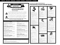 2
2
-
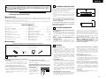 3
3
-
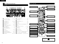 4
4
-
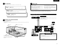 5
5
-
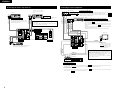 6
6
-
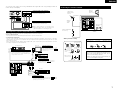 7
7
-
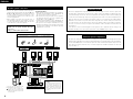 8
8
-
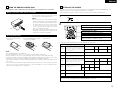 9
9
-
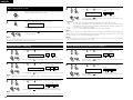 10
10
-
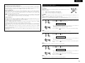 11
11
-
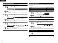 12
12
-
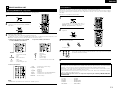 13
13
-
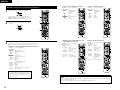 14
14
-
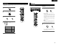 15
15
-
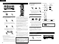 16
16
-
 17
17
-
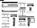 18
18
-
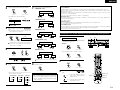 19
19
-
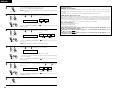 20
20
-
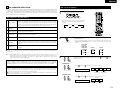 21
21
-
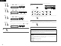 22
22
-
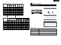 23
23
-
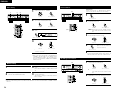 24
24
-
 25
25
-
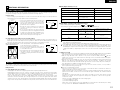 26
26
-
 27
27
-
 28
28
-
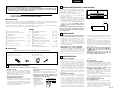 29
29
-
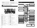 30
30
-
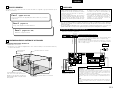 31
31
-
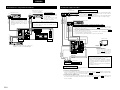 32
32
-
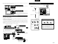 33
33
-
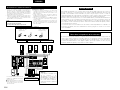 34
34
-
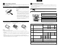 35
35
-
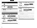 36
36
-
 37
37
-
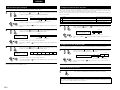 38
38
-
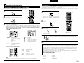 39
39
-
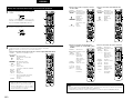 40
40
-
 41
41
-
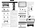 42
42
-
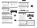 43
43
-
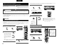 44
44
-
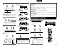 45
45
-
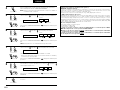 46
46
-
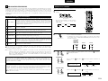 47
47
-
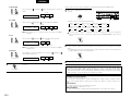 48
48
-
 49
49
-
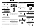 50
50
-
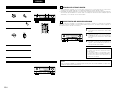 51
51
-
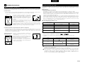 52
52
-
 53
53
-
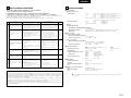 54
54
-
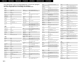 55
55
-
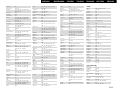 56
56
-
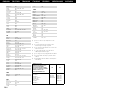 57
57
-
 58
58


Denon AVR-1603 Manuale utente
- Categoria
- Ricevitori AV
- Tipo
- Manuale utente
in altre lingue
- English: Denon AVR-1603 User manual
- español: Denon AVR-1603 Manual de usuario
Documenti correlati
-
Denon AVR-2802 Operating Instructions Manual
-
Denon AVR 3802 Operating Instructions Manual
-
Denon AVR-1707 Manuale utente
-
Denon PMA-1500AE Manuale utente
-
Denon AVR-1603 Manuale del proprietario
-
Denon AVR-1803 Operating Instructions Manual
-
Denon AVR-1804 Operating Instructions Manual
-
-
Denon AVR-2105 Operating Instructions Manual
-