resideo Braukmann TS131 Guida d'installazione
- Tipo
- Guida d'installazione

R32347455-001 Rev.A
Braukmann
TS131
Installation instructions Einbauanleitung Instructions d'installation Istruzioni di montaggio
Instrukcja montażu
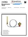
Temperature Relief Valve
Thermische Ablaufsicherung
Thermique d'écoulement
Valvola di scarico termico
Termiczne zabezpieczenie
Strandvejen 42 Saksild 8300 Odder
86 62 63 64 www.automatikcentret.dk
info@automatikcentret.dk

GB
2 MU1H-1543GE23 R0420
1 Safety Guidelines
1. Follow the installation instructions.
2. Use the appliance
• according to its intended use
• in good condition
• with due regard to safety and risk of danger.
3. Note that the appliance is exclusively for use in the
applications detailed in these installation instructions
(see 2 Technical Data). Any other use will not be
considered to comply with requirements and would
invalidate the warranty.
4. Please take note that any assembly, commissioning,
servicing and adjustment work may only be carried
out by authorized persons.
5. Immediately rectify any malfunctions which may
influence safety.
2 Technical Data
3 Options
For Options visit homecomfort.resideo.com/europe
4 Assembly
4.1 Installation Guidelines
• The valve and the sensor must be installed carefully
to avoid any damage to the capillary tube
• The opening on the blow-out line must be clear and
easy to monitor
• Ensure no persons are in danger when blowing off the
valve
• A sufficiently dimensioned discharge line must be
provided
CAUTION!
Installation of the thermal discharge safety valve
does not replace the diaphragm relief value in the
cold water supply line to the water heater.
4.2 Assembly instructions
1. Install a thermal discharge safety valve according to
the installation diagram
• Flow direction is indicated by an arrow
2. Push the heat sensor into the immersion pipe up to the
stop point and secure with a round screw to stop it
being pulled out
5 Start-up
CAUTION!
On commissioning the heating system, the person
preparing the system must check that the thermal
discharge safety valve is functioning perfectly.
6 Maintenance
In order to comply with EN 806-5, water fixtures must
be inspected and serviced on an annual basis.
As all maintenance work must be carried out by an
installation company, it is recommended that a
servicing contract should be taken out.
In accordance with EN 806-5, the following measures must
be taken:
Media
Medium: Drinking water
Connections/Sizes
Connection sizes: Rp 3/4" (DIN EN 10226)
Pressure values
Max. operating pressure: 10 bar
Operating temperatures
Operating temperatures:
TS131-3/4 A+B
TS131-3/4ZAx
95 °C
x =50 / 100 / 110 °C
Max. ambient temperature: 70 °C
Specifications
Heating system capacity: max. 100 kW
Capacity: 2800 kg/h water at the
pressure drop p=1 bar
(Inlet pressure 5 bar; Outlet
pressure 4 bar; 110°C
medium temperature) (1
capillary tube)
Mode of operation: 2 Kp
Solid/dual-fuel boilers with
integrated water heater or
cooling coil in closed heating
systems according to EN
12828
kVS value: p = 1 bar
3 m3/h: with 2 intact sensor systems
(with a media temperature of 110 °C)
2.1 m3/h: with one sensor system
(with a media temperature of 110 °C)

GB
MU1H-1543GE23 R0420 3
6.1 Inspection and Maintenance
Do not use any cleansers that contain solvents and/or
alcohol for cleaning the plastic parts, because this can
cause damage to the plastic components - water
damage could result.
Detergents must not be allowed to enter the
environment or the sewerage system!
• According to the requirements of EN 12828, the
system operator is obliged to have the thermal
discharge safety valve checked by a professional at
least once a year to ensure its functional readiness.
1. Check whether water is escaping from the housing
• if water is escaping, the seals (entire piston guide)
must be replaced, or it may be necessary to
replace the unit
2. Operate the check valve and first check whether water
is escaping and the valve then closes again
• if no water is escaping or the valve does not close,
the unit may have to be replaced
7 Disposal
Observe the local requirements regarding correct waste
recycling/disposal!
8 Spare Parts
For Spare Parts visit homecomfort.resideo.com/europe

D
4 MU1H-1543GE23 R0420
1 Sicherheitshinweise
1. Beachten Sie die Einbauanleitung.
2. Benutzen Sie das Gerät
• bestimmungsgemäß
• in einwandfreiem Zustand
• sicherheits- und gefahrenbewusst.
3. Beachten Sie, dass das Gerät ausschließlich für den
in dieser Einbauanleitung genannten
Verwendungsbereich bestimmt ist (siehe
2 Technische Daten). Eine andere oder darüber
hinausgehende Benutzung gilt als nicht
bestimmungsgemäß.
4. Beachten Sie, dass alle Montage-, Inbetriebnahme,
Wartungs- und Justagearbeiten nur durch autorisierte
Fachkräfte ausgeführt werden dürfen.
5. Lassen Sie Störungen, welche die Sicherheit
beeinträchtigen können, sofort beseitigen.
2 Technische Daten
3 Produktvarianten
Produktvarianten finden Sie unter homecomfort.resideo.com/
europe
4 Montage
4.1 Einbauhinweise
• Der Einbau des Ventiles und des Fühlers ist sorgfältig
vorzunehmen, damit Beschädigungen des
Kapillarrohres vermieden werden
• Die Mündung der Ausblaseleitung muss frei und
beobachtbar sein
• Personen dürfen beim Abblasen der Armatur nicht
gefährdet werden
• Es ist eine ausreichend bemessene Ablaufleitung
vorzusehen
VORSICHT!
Der Einbau der thermischen Ablaufsicherung
ersetzt nicht das Membran-Sicherheitsventil in der
Kaltwasser-Zuführungsleitung zum
Wassererwärmer.
4.2 Montageanleitung
1. Thermische Ablaufsicherung entsprechend dem
Einbauschema einbauen
• Durchflussrichtung ist durch Pfeil gekennzeichnet
2. Wärmefühler bis zum Anschlag in das Tauchrohr
einschieben und mit der Rundkopfschraube gegen
Herausziehen sichern
5 Inbetriebnahme
VORSICHT!
Bei Inbetriebnahme der Heizungsanlage muss der
Ersteller der Anlage die einwandfreie Funktion der
thermischen Ablaufsicherung überprüfen.
6 Instandhaltung
Nach DIN EN 806-5 sind Wasserarmaturen jährlich zu
prüfen und instandzuhalten.
Instandhaltungsarbeiten müssen durch ein
Installationsunternehmen durchgeführt werden, es
wird empfohlen einen Instandhaltungsvertrag mit
einem Installationsunternehmen abzuschließen.
Entsprechend DIN EN 806-5 sind folgende Maßnahmen
durchzuführen:
Medien
Medium: Trinkwasser
Anschlüsse/Größen
Anschlussgrößen: Rp
3/4" (DIN EN 10226)
Druckwerte
Max. Betriebsdruck: 10 bar
Betriebstemperaturen
Betriebstemperaturen:
TS131-3/4 A+B
TS131-3/4ZAx
95 °C
x =50 / 100 / 110 °C
Max. Umgebungstemperatur: 70 °C
Spezifikationen
Leistungen der
Heizungsanlagen:
max. 100 kW
Leistung: 2800 kg/h Wasser bei einem
Druckabfall von Δp=1 bar
(Eingangsdruck 5 bar,
Ausgangsdruck 4 bar; 110°C
Mediumstemperatur) (1
Fühler)
Funktionsweise: 2 Kp
Feststoff-/
Wechselbrandkessel mit
eingebautem
Wassererwärmer oder
Kühlschlange in
geschlossenen
Heizungsanlagen nach DIN
EN 12828
kvs-Wert: p = 1 bar
3 m3/h: bei 2 unversehrten Fühlersystemen
(bei einer Medientemperatur von 110 °C)
2,1 m3/h: bei einem Fühlersystem
(bei einer Medientemperatur von 110 °C)

D
MU1H-1543GE23 R0420 5
6.1 Inspektion und Wartung
Zum Reinigen der Kunststoffteile keine lösungsmittel-
und/oder alkoholhaltigen Reinigungsmittel benutzen,
da dies zu Schädigung der Kunststoffbauteile führen
kann - die Folge kann ein Wasserschaden sein!
Es dürfen keine Reinigungsmittel in die Umwelt oder
Kanalisation gelangen!
• Entsprechend den Forderungen der DIN EN 12828 ist
der Betreiber der Anlage verpflichtet, die thermische
Ablaufsicherung mindestens einmal jährlich durch
einen Fachkundigen auf ihre Funktionsbereitschaft
prüfen zu lassen
1. Prüfen ob Wasser aus dem Gehäuse austritt
• tritt Wasser aus müssen die Dichtungen
(Kolbenführung komplett) ersetzt oder das Gerät
gegebenfalls ausgetauscht werden
2. Kontrollkappe betätigen und prüfen ob zunächst
Wasser abläuft und das Ventil anschließend wieder
schließt
• tritt kein Wasser aus oder schließt das Ventil nicht
muss das Gerät gegebenfalls ausgetauscht
werden
7 Entsorgung
Die örtlichen Vorschriften zur korrekten Abfallverwertung/-
entsorgung beachten!
8 Ersatzteile
Ersatzteile finden Sie unter homecomfort.resideo.com/
europe

F
6 MU1H-1543GE23 R0420
1 Règles de sécurité
1. Suivez les instructions d'installation.
2. Utilisez le dispositif
• Conformément à l'usage auquel il est destiné
• Dans un bon état
• En tenant dûment compte de la sécurité et des
risques.
3. Notez que le dispositif est exclusivement réservé à
une utilisation dans les applications décrites en détails
dans les présentes instructions d'installation (Voir
2 Caractéristiques techniques). Toute autre utilisation
sera considérée comme non conforme aux exigences
et entraînera une annulation de la garantie.
4. Notez que seules les personnes autorisées sont
habilitées à effectuer les travaux d'assemblage, de
mise en service, de maintenance et de réglage.
5. Éliminez immédiatement tout dysfonctionnement
susceptible d'entraver la sécurité.
2 Caractéristiques techniques
3 Options
Pour les options, visitez homecomfort.resideo.com/europe
4 Assemblage
4.1 Consignes d'installation
• Le montage de la soupape et du capteur doit être
effectué prudemment afin de ne pas endommager le
tube capillaire
• L’embouchure de la conduite de sortie doit être libre et
observable
• Les personnes ne doivent pas être mises en danger
par le crachement de la robinetterie
• Il convient de prévoir une conduite d’écoulement
suffisante
ATTENTION!
Le montage de la sécurité thermique d’écoulement
ne remplace pas la soupape de sécurité à
membrane dans la conduite d’alimentation d’eau
froide vers le chauffe-eau.
4.2 Instructions d'assemblage
1. Montez la sécurité thermique d'écoulement, selon le
plan de montage
• La direction du courant est marquée par une
flèche
2. Glissez les thermocapteur dans la douille d'immersion
jusqu'à la butée et sécurisez avec une vis à tête ronde
5 Démarrage
ATTENTION!
Lors de la mise en service de l'installation de
chauffage, le constructeur du système doit
contrôler le fonctionnement parfait de la sécurité
thermique d'écoulement.
6 Maintenance
Conformément à EN 806-5 les sraccords d'eau
doivent être inspectées et entretenues une fois par
an.
Les travaux de maintenance doivent être réalisés par
une société d'installation, nous recommandons de
signer un contrat de maintenance planifiée avec une
société d'installation.
Les mesures ci-après doivent être effectuées conformément
à EN 806-5 :
Fluides
Milieu: Eau potable
Raccords/tailles
Tailles des raccords: Rp 3/4" (DIN EN 10226)
Valeurs de pression
Pression de service
max.:
10 bar
Températures de fonctionnement
Températures de
fonctionnement:
TS131-3/4 A+B
TS131-3/4ZAx
95 °C
x =50 / 100 / 110 °C
Température ambiante
maximale:
70 °C
Spécifications
Puissances de
l’installation de
chauffage:
max. 100 kW
Capacité: 2800 kg/h d’eau pour une perte
de charge Δ p=1 bar (Pression
amont 5 bar, Pression aval 4 bar,
1 tube capillaire pour une
température du milieu de 110 °C)
Mode d’action: 2 Kp
Chaudière à combustible solide/
chaudière mixte à chauffeau
intégré ou serpentin de
refroidissement dans des
systèmes de chauffage fermés
selon EN12828
Valeur du kvs: p = 1 bar
3 m3/h: avec 2 systèmes intacts de capteurs
(pour une température du milieu de 110 °C)
2,1 m3/h: avec un système de capteurs
(pour une température du milieu de 110 °C)

F
MU1H-1543GE23 R0420 7
6.1 Inspection et maintenance
Pour le nettoyage des pièces en matière synthétique,
n'utilisez pas de produits solvants ni contenant de
l'alcool, car cela pourrait provoquer des dégâts d'eau!
Il est interdit de déverser les détergents dans
l'environnement ou dans le réseau des égouts !
• En accord avec la DIN EN 12828, l’exploitant de
l’installation s’oblige à faire contrôler le
fonctionnement de la sécurité thermique
d’écoulement une fois par an par du personnel
spécialisé.
1. Contrôlez si l'eau sort du boîtier
• Si de l’eau fuit, alors les joints (guide des pistons
complet) doivent être remplacés ou
éventuellement l’appareil échangé
2. Actionnez le clapet de contrôle et contrôlez d’abord si
l’eau coule et si la soupape ensuite se referme
• Si l'eau ne coule pas ou si la soupape ne se
referme pas, alors l'appareil doit être échangé
7 Mise au rebut
Observez les exigences locales en matière de recyclage /
d'élimination conforme des déchets !
8 Pièces de rechange
Pour les pièces de rechange, visitez
homecomfort.resideo.com/europe

I
8 MU1H-1543GE23 R0420
1 Avvertenze di sicurezza
1. Rispettare le istruzioni di installazione.
2. Utilizzare l'apparecchio
• secondo la destinazione d'uso
• solo se integro
• in modo sicuro e consapevoli dei pericoli connessi.
3. Si prega di considerare che l'apparecchio è realizzato
esclusivamente per gli impieghi riportati nelle presenti
istruzioni (Vedere 2 Dati tecnici). Un uso differente da
quello previsto è da considerarsi non conforme ai
requisiti e annullerebbe la garanzia.
4. Osservare che tutti i lavori di montaggio, di messa in
funzione, di manutenzione e di regolazione devono
essere eseguiti soltanto da personale autorizzato.
5. I guasti che potrebbero compromettere la sicurezza
devono essere risolti immediatamente.
2 Dati tecnici
3 Opzioni
Per gli opzioni, visita homecomfort.resideo.com/europe
4 Montaggio
4.1 Istruzioni di installazione
• L'installazione della valvola e del sensore deve essere
eseguita con attenzione per evitare danni al tubo
capillare
• La bocca del tubo di scarico deve essere libera e
visibile
• Si raccomanda di non mettere in pericolo le persone
durante lo scarico della valvola
• Prevedere un tubo di scarico della misura adeguata
ATTENZIONE!
L'installazione della valvola di scarico termico non
sostituisce la valvola di sicurezza a membrana
presente nella condotta di alimentazione dell'acqua
fredda verso lo scaldacqua.
4.2 Istruzioni di montaggio
1. Montare la valvola di scarico termico secondo lo
schema di montaggio
• La direzione del flusso è indicata dalla freccia
2. Inserire il termorivelatore nel tubo ad immersione fino
all'arresto e assicurarlo con la vite a testa tonda in
modo che non esca
5 Messa in servizio
ATTENZIONE!
Al momento della messa in funzione dell'impianto di
riscaldamento, il realizzatore dell'impianto deve
controllare che il funzionamento della valvola di
scarico termico sia perfetto.
6 Manutenzione
Stando ai requisiti posti dalle norme DIN EN 806-5
apparecchi per l'acqua vanno controllate e sottoposte
a manutenzione una volta l'anno.
I lavori di manutenzione devono essere eseguiti da
un'azienda di installazione, consigliamo di stipulare
un contratto di manutenzione con un'azienda di
installazione.
In conformità alla norma EN 806-5, è necessario eseguire le
seguenti operazioni:
Fluidi
Fluido: Acqua potabile
Attacchi/dimensioni
Dimensioni dell'attacco: Rp 3/4" (DIN EN 10226)
Valori di pressione
Pressione di esercizio max.: 10 bar
Temperature di esercizio
Temperature di esercizio:
TS131-3/4 A+B
TS131-3/4ZAx
95 °C
x =50 / 100 / 110 °C
Temperatura ambiente max.: 70 °C
Specifiche
Prestazioni degli impianti di
riscaldamento:
max. 100 kW
Capacità: 2800 kg/h di acqua con
caduta di pressione pari a Δp
= 1 bar (Pressione a monte 5
bar, Pressione a valle 4 bar, 1
sensore e temperatura del
mezzo pari a 110 °C
Funzionamento: 2 Kp
Caldaia a combustibili solidi /
due combustibili con
scaldacqua integrato o
serpentina refrigerante in
impianti di riscaldamento
chiusi in conformità alla
normativa europea EN12828.
Valore kvs: p = 1 bar
3 m3/h: Con due sistemi di sensori integri
(temperatura del mezzo pari a 110 °C)
2,1 m3/h: Con un sistema di sensori
(temperatura del mezzo pari a 110 °C)

I
MU1H-1543GE23 R0420 9
6.1 Ispezione e manutenzione
Per pulire le parti in plastica non utilizzare alcun
detergente contenente solvente o alcol, poiché questi
potrebbero provocare danni all'acqua.
Nell'ambiente o nella canalizzazione è necessario che
non venga scaricato alcun detergente!
• La norma DIN EN 12828 impone all'operatore
dell'impianto di far controllare la funzionalità della
valvola di scarico termico almeno una volta all'anno
per mezzo di personale specializzato.
1. Controllare se fuoriesce acqua dal corpo
• In questo caso sostituire le guarnizioni (la guida
del pistone deve essere sostituita completamente)
oppure, se necessario, l'intero apparecchio
2. Azionare il coperchio di controllo e controllare se
l'acqua scorre e se la valvola si richiude
successivamente
• se l'acqua non fuoriesce o se la valvola non si
chiude, sostituire l'apparecchio se necessario
7 Smaltimento
Rispettare le norme locali relative al corretto riciclaggio o
smaltimento di rifiuti!
8 Pezzi di ricambio
Per gli pezzi di ricambio, visita homecomfort.resideo.com/
europe

PL
10 MU1H-1543GE23 R0420
1 Wskazówki dotyczące
bezpieczeństwa
1. Przestrzegać instrukcji montażu.
2. Używać urządzenia
• zgodnie z jego przeznaczeniem;
• w dobrym stanie;
• ze świadomością bezpieczeństwa i zagrożeń.
3. Należy pamiętać, że urządzenie jest przeznaczone
wyłącznie do zastosować określonych w niniejszej
instrukcji montażu (Patrz 2 Dane techniczne). Każde
inne zastosowanie uznaje się za niezgodne z
przeznaczeniem.
4. Należy również pamiętać, że wszelkie prace
związane z montażem, rozruchem, serwisowaniem i
regulacją mogą wykonywać wyłącznie upoważnieni
do tego pracownicy.
5. Wszelkie usterki mogące stanowić zagrożenie należy
natychmiast usuwać.
2 Dane techniczne
3 Opcje
Opcje zobacz stronę homecomfort.resideo.com/europe
4 Montaż
4.1 Wskazówki dotyczące montażu
• Montaż zaworu oraz czujnika należy przeprowadzić w
staranny sposób, aby nie uszkodzić rurki kapilarnej
• Wylot przewodu wydmuchowego nie może być
zatkany i musi być widoczny
• Wydmuch z armatury nie może stanowić zagrożenia
dla ludzi
• Należy zastosować przewód odprowadzający o
odpowiednich wymiarach
OSTROŻNIE!
Montaż zabezpieczenia termicznego nie zastępuje
przeponowego zaworu bezpieczeństwa w układzie
doprowadzającym wodę zimną do podgrzewacza
wody.
4.2 Instrukcja montażu
1. Zainstalowa termiczne zabezpieczenie odpywu
zgodnie ze wskazówkami na schemacie
instalacyjnym
• Kierunek przepływu oznaczono strzałką
2. Czujnik termiczny wsunąć do
oporu w rurkę zanurzeniową
zabezpieczyć przed wyciagnięciem
śrubą
5 Uruchomienie
OSTROŻNIE!
Przed oddaniem instalacji do
użytku wykwalifi kowany instalator
powinien sprawdzić
popraw ność działania zabezpieczenia
termicznego.
6 Utrzymywanie w dobrym stanie
Aby zachować zgodność z EN 806-5, armatura
wodna musi być sprawdzana i serwisowana co roku.
Prace konserwacyjne muszą być wykonywane przez
firmę montażową, zalecamy zawarcie umowy
serwisowej z firmą instalacyjną.
Zgodnie z normą EN 806-5, należy wykonać następujące
czynności:
Czynniki
Czynnik: Woda pitna
Przyłącza/rozmiary
Rozmiary przyłączy: Rp
3/4" (DIN EN 10226)
Wartości ciśnienia
Maks. ciśnienie robocze: 10 bar
Temperatury robocze
Temperatury robocze:
TS131-3/4 A+B
TS131-3/4ZAx
95 °C
x =50 / 100 / 110 °C
Maks. temperatura
otoczenia:
70 °C
Specyfikacja
Moc instalacji grzewczej: maks. 100 kW
Pojemność: 2800 kg/h wody przy spadku
ciśnienia Δp = 1 bar
(ciśnienie wejściowe 5 bar,
Ciśnienie wylotowe 4 bar, 1
czujnik przy temperaturze
medium 110°C)
Sposób działania: 2 Kp
Kotły na paliwa stałe / kotły
do zmiennego spalania z
wbudowanym
podgrzewaczem wody lub
wężownicą chłodzącą w
zamkniętych instalacjach
grzewczych
skonstruowanych zgodnie z
normą EN12828.
Wartość kvs: p = 1 bar
3 m3/h: przy 2 sprawnych systemach czujników
(przy temperaturze medium 110°C)
2,1 m3/h: przy jednym systemie czujników
(przy temperaturze medium 110°C)

PL
MU1H-1543GE23 R0420 11
6.1 Przeglądy i konserwacja
Do czyszczenia części z tworzyw sztucznych nie
należy używaę rozpuszczalników i/lub środków zawi
erających alkohol. Prowadzię to może do uszkod
zenia tych części, a konsekwencją tego mogą byę
szkody wodne!
Nie wolno uwalniać detergentów do środowiska ani do
kanalizacji ściekowej!
• Zgodnie z wymogami normy DIN EN 12828
użytkujący instalację ma obowiązek zlecić
wykwalifikowanemu instalatorowi przynajmniej raz w
roku kontrolę poprawności działania zabezpieczenia
termicznego
1. Należy sprawdzić, czy z
korpusu nie wycieka woda
• W przypadku wycieku wody należy wymienić
uszczelnienia (kompletny zespół tłoka) lub w razie
potrzeby — całe urządzenie
2. Uruchomić pokrywę kontrolną i sprawdzić, czy
odpływa woda, a zawór następnie ponownie się
zamyka
•jeżeli nie wypływa woda lub
zawór nie zamyka urządzenie
należy wymienić
7 Utylizacja
Należy stosować się do miejscowych przepisów dotyczących
prawidłowego wykorzystania odpadów, względnie ich
utylizacji.
8Części zamienne
Części zamienne zobacz stronę homecomfort.resideo.com/
europe

Manufactured for
and on behalf of
Pittway Sàrl, Z.A., La Pièce 4,
1180 Rolle, Switzerland
by its authorised representative
Ademco 1 GmbH
© 2020 Resideo Technologies, Inc. All rights reserved.
For more information
homecomfort.resideo.com/europe
Ademco 1 GmbH, Hardhofweg 40,
74821 MOSBACH, GERMANY
Phone: +49 6261 810
Fax: +49 6261 81309
Subject to change. MU1H-1543GE23 R0420

MU1H-1543GE23 R0420 13
GB
1 Safety Guidelines . . . . . 2
2 Technical Data . . . . . . . . 2
3 Options . . . . . . . . . . . . . 2
4 Assembly . . . . . . . . . . . . 2
5 Start-up . . . . . . . . . . . . . 2
6 Maintenance . . . . . . . . . 2
7 Disposal. . . . . . . . . . . . . 3
8 Spare Parts . . . . . . . . . . 3
D
1 Sicherheitshinweise. . . . 4
2 Technische Daten . . . . . 4
3 Produktvarianten . . . . . . 4
4 Montage. . . . . . . . . . . . . 4
5 Inbetriebnahme . . . . . . . 4
6 Instandhaltung . . . . . . . . 4
7 Entsorgung . . . . . . . . . . 5
8 Ersatzteile . . . . . . . . . . . 5
F
1 Règles de sécurité. . . . . 6
2 Caractéristiques
techniques . . . . . . . . . . . 6
3 Options . . . . . . . . . . . . . 6
4 Assemblage . . . . . . . . . . 6
5 Démarrage. . . . . . . . . . . 6
6 Maintenance . . . . . . . . . 6
7 Mise au rebut. . . . . . . . . 7
8 Pièces de rechange. . . . 7
I
1 Avvertenze di sicurezza. 8
2 Dati tecnici . . . . . . . . . . . 8
3 Opzioni . . . . . . . . . . . . . 8
4 Montaggio . . . . . . . . . . . 8
5 Messa in servizio . . . . . . 8
6 Manutenzione . . . . . . . . 8
7 Smaltimento. . . . . . . . . . 9
8 Pezzi di ricambio . . . . . . 9
PL
1 Wskazówki dotyczące
bezpieczeństwa . . . . . . 10
2 Dane techniczne . . . . . 10
3 Opcje . . . . . . . . . . . . . . 10
4 Montaż. . . . . . . . . . . . . 10
5 Uruchomienie . . . . . . . 10
6 Utrzymywanie w dobrym
stanie . . . . . . . . . . . . . . 10
7 Utylizacja . . . . . . . . . . . 11
8Części zamienne . . . . . 11
-
 1
1
-
 2
2
-
 3
3
-
 4
4
-
 5
5
-
 6
6
-
 7
7
-
 8
8
-
 9
9
-
 10
10
-
 11
11
-
 12
12
-
 13
13


resideo Braukmann TS131 Guida d'installazione
- Tipo
- Guida d'installazione
in altre lingue
Documenti correlati
Altri documenti
-
Honeywell SM110- 1/2A3.0 Manuale del proprietario
-
Honeywell SM150 Manuale del proprietario
-
-
-
-
-
-
-
-
resistex R200 Manuale utente