Frigomat Taylor C122 03 Series Operating
- Categoria
- Fabbricatori di cubetti di ghiaccio
- Tipo
- Operating
Questo manuale è adatto anche per

MANTECATORI ORIZZONTALI ELETTRONICI
ELECTRONIC HORIZONTAL BATCH FREEZER
MANUALE D’USO
E
MANUTENZIONE
OPERATING INSTRUCTION
AND MAINTENANCE
Serie-Series-Série-Serie
C119 06
C122 03

1 - ENGLISH
IMPORTANT
We recommend that you read this manual fully and carefully before using your
appliance.
It is in your interest to pay special attention to the warnings marked as follows:
Failure to comply with this signal causes very serious risks for health, death, and
medium and long term permanent damage.
Failure to comply with this signal can cause very serious risks for heath, death, and
medium and long term permanent damage.
Failure to comply with this signal can cause injuries or damage to the machine.
Comply with these warnings for your machine to work properly and/or to be serviced
correctly.
The machine can perform at best only through careful observance of these
warnings.
FRGMTMEB2DGT2916000

ENGLISH - 2
We congratulate you for having chosen to purchase a TAYLOR machine.
This manual, supplied together with the machine, must be considered as an integral and
essential part of it and must be delivered to the final user. Before carrying out any
operations, we recommend studying these instructions carefully. Only by reading them
carefully can you obtain the maximum performance from your machine. The following
pages carry all of the indications required to correctly perform installation, operation,
adjustments and routine maintenance. TAYLOR reserves the right to carry out the
modifications it deems necessary to improve its product or the technical manual without
prior warning, inserting the variations in the subsequent editions.
Total and/or partial reproduction, adaptation or translations of this manual without prior
written consent by TAYLOR S.r.l is prohibited.
The machine is covered by warranty according to the terms illustrated in the "WARRANTY
CARD" supplied. It must be properly filled in and returned to:
FRIGOMAT s.r.l., via 1° Maggio, 28 26862 GUARDAMIGLIO (LODI) – ITALY
Please write the serial number of your machine in the field below.
Serial number
Stamp of dealer

3 - ENGLISH
INDEX
1. TRANSPORTATION, HANDLING AND STORAGE……… 4
1.1 Preliminary inspection …………………………………… 4
1.2 Dimensions and weights of packaged machines…………… 4
1.3 Indications for decommissioning ……………… 4
2. MARKING AND GRAPHIC SIGNS ………………………………………… 5
3. GENERAL SAFETY STANDARDS …………………………………… 7
4. INSTALLATION ………………………………………… 8
4.1 Use ………………………………………… 8
4.2 Working limits ………………………………………… 8
4.3 Noise ………………………………………… 8
4.4 Supplied with machine ………………………………………… 8
4.5 Activation ………………………………………… 9
5. SAFETY DEVICES ………………………………………… 12
6. OPERATION ………………………………………… 13
6.1 Machine ………………………………………… 13
6.2 Controls ………………………………………… 14
6.3 Slush and ice cream production………………………………………… 16
6.3.1 Automatic cycle ………………………………………… 17
6.3.2 Automatic hard cycle .................………………………… 18
6.3.3 Semi-automatic cycle with consistency control ………… 19
6.3.4 Semi-automatic cycle with time control ………… 21
6.3.5 Slush program ..............................................………. 23
6.3.6 Coffee slush program ................................………… 25
6.4 Extraction . .………………………………………… 27
7. MAINTENANCE ………………………………………... 28
7.1 Routine maintenance ………………………………………… 28
7.2 Extraordinary maintenance ………………………………………… 33
8. INSTRUCTIONS FOR IDENTIFYING FAILURES ………………… 36
8.1 Alarm management ………………………………………… 36
8.2 Troubleshooting ………………………………………… 37
9. APPENDIXES ………………………………………… A1
9.1 Technical data ………………………………………… A1
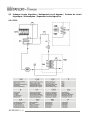
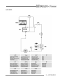
9.2 Refrigeration circuit layouts ………………………………………… A2
9.2.1 T4S ………………………………………… A2
9.2.2 T5S ………………………………………… A3
9.3 Electrical system ………………………………………… A4
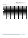
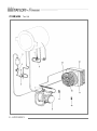
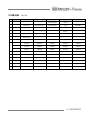
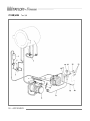
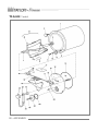
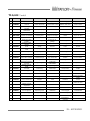
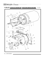
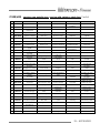
9.4 Spare parts ………………………………………… A5

ENGLISH - 4
1 TRANSPORTATION, HANDLING AND STORAGE.
1.1 PRELIMINARY INSPECTION AND STORAGE
The machine is transported at the risk and peril of the customer. If you notice any damage
to the packaging, immediately inform the carrier.
Inform the carrier right after opening the package if the machine is damaged even if it is a
few days after delivery.
It is always preferable to accept goods SUBJECT TO CLEARANCE.
The appliance must be handled with care; it can be damaged by falls and blows even
without exterior damages.
Storage temperature must be between 0° and + 50°C, and humidity between 30 and 95%
with no dew.
Once the appliance has been unpacked, the packaging must be kept in a dry place out of
the reach of children. If stored properly, it can be reused if the machine is moved.
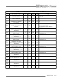
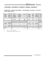
1.2 DIMENSIONS AND WEIGHTS OF PACKAGED MACHINES
MODEL
CRATE
BOX PALLET
MEASUREMENTS
(CM)
WEIGHT N-G
(KG)
MEASUREMENTS
(CM)
WEIGHT N-G
(KG)
C119
85,5X52X144
170 – 240
85,5X52X144
170 - 220
C122
90X52X93
130 - 195
90X52X93
130 - 175
1.3 INDICATIONS FOR DECOMMISSIONING
The machine contains electrical and/or electronic materials and can
contain fluids and/or oil. If it needs to be decommissioned or
disposed of, comply with the standards in force in the Country where
it is used.
Even packaging materials (crates or boxes) must be divided by type
and disposed of in compliance with standards in force in the Country
where it is used when the machine is decommissioned.

5 - ENGLISH
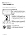
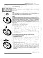
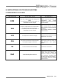
2. MARKING AND GRAPHIC SIGNS
The machine is provided with an identification plate and some pictograms. They must be
known along with the manual to guarantee safe use.
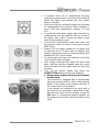
Machine data plate
The adhesive plate applied on the rear enables to
identify the model. It includes the following indications:
Name and address of the manufacturer; machine
model and version; serial number; nominal electrical
features; type and weight of gas used; year of
manufacture.
Indication
Lifting equipment hooking points:
This plate indicates the points where the lifting hooks
must be placed to carry out this operation safely. Use
a Phillips screwdriver to unscrew the two side panels
of the machine and position the lifting equipment in
the relevant points, making sure that they cannot
accidentally slip off during lifting operations.
Attention!
Maintenance reserved for qualified personnel. This
plate applied on the rear panel prohibits extraordinary
maintenance and/or repairs to anyone but authorised
personnel, whose address is indicated in the space
provided.
Attention!
Do not touch with your hands.
This plate applied on the rear panel of machines with
air cooling indicates that the heat exchanger can only
be cleaned using a brush or vacuum cleaner.

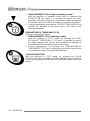
ENGLISH - 6
Attention!
High voltage inside; danger of electrocution.
This plate is applied on the cover of the electrical box
and warns the operator that it must not be removed
for any reason whatsoever, thus avoiding the danger
of electrocution which could be fatal. In this case as
well, maintenance of internal components is reserved
for qualified personnel.

7 - ENGLISH
3. GENERAL SAFETY STANDARDS
Strictly observe the general safety and accident-prevention standards listed hereafter:
- Use of the machine is NOT suitable for persons (including children) having reduced
physical, sensorial or mental abilities, or lacking in experience and knowledge,
unless supervised or trained on using the machine by a personal responsible for
their safety.
Children must be supervised to avoid them playing with the machine.
-
- Use of the machine is reserved for operators who have read, understood and taken
in all that is included in this manual.
- It is forbidden to remove or tamper with the safety systems installed on the
machine.
- While the appliance is operating, it is mandatory to check that danger situations for
persons do not occur. Should these conditions occur, stop the appliance
immediately.
- When you have finished working with the machine, it is mandatory to cut power by
acting on the master switch.
- When unusual noise or anomalous functioning is perceived, it is mandatory to
immediately stop operations in progress and to search for the cause of these
irregularities. If in doubt, avoid improper operations by contacting the technical
assistance service of the manufacturer.
- Any tampering or modification of the machine automatically entails the immediate
termination of the warranty and relieves the manufacturer of all and any liability for
direct or indirect damage caused.
- It is mandatory to check that the place where the machine is installed is ventilated
and correctly illuminated. The surface where the appliance is installed must be
solid, flat and levelled.
- During loading, unloading and handling operations, it is mandatory to use
equipment with a capacity adequate for the mass (weight) of the machine, using
hoisting devices and accessories with features and state of use suitable for the
purpose.
- Use only original TAYLOR spare parts when performing maintenance. The
manufacturer will not be held liable for damage caused by use of non-original spare
parts. Use of non-original spare parts entails automatic termination of the warranty.
- It is mandatory to position the machine far away from equipment which emits
electromagnetic radiation which could cause the circuit boards to malfunction.
- If fire-prevention equipment needs to be used, use types which are compatible with
the presence of voltage on board.
- It is forbidden to wear long and loose apparel, ties, jewellery, scarves or similar
clothing which could get caught in the moving parts of the machine.
- Hair must be tied and shirt-sleeves tight.

ENGLISH - 8
4. INSTALLATION
4.1 USE
Appliance suitable for batch freezing of ice cream mixtures and slush production,
according to use allowed by Law.
4.2 WORKING LIMITS
Do not use the machine with inconstant power supplies or +/- 10% beyond the value
indicated on the plate or with the power cable damaged;
Do not use the machine in explosive atmospheres;
Do not wash the machine with high-pressure water jets or with harmful substances;
Do not expose the machine to excessive heat or humidity;
Do not use unbalanced mixtures and/or amounts which do not comply with the
specifications carried on the packs.
Use not expressly indicated in this manual is to be considered improper and therefore
must be strictly avoided.
The manufacturer will not be held liable for direct or indirect harm to persons or animals or
damage to objects caused by improper use of the machine.
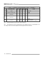
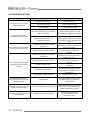
4.3 NOISE
SOUND EMISSION LEVEL EXPRESSED IN DECIBELS (measurement method A)
As foreseen by Machinery Directive 89/392 standard EN 23741
(A-weighted equivalent continuous sound pressure level)
MODEL
LEVEL (A)
MODEL
LEVEL (A)
C119
< = 68 dB (A)
C122
< = 68 dB (A)
4.4 SUPPLIED WITH MACHINE
-
- Ice cream extraction spatula
- Complete scrapers
- Centring pin for beater
- Brush
- Gasket extractor
- O-ring kit
- Rubber seal
- Lubricant
- Use and maintenance manual
- Declaration of conformity
- Warranty certificate
-

9 - ENGLISH
4.5 ACTIVATION
TAYLOR declines all and any liability for damage caused by failure to comply with the
following indications. This lack of compliance causes the warranty to terminate.
Connection of the machine to the water mains must be performed respecting national
regulations of the Country where the machine is installed.
To commission the machine, bring it to the place of use, checking what is requested for its
installation:
1. Electrical power supply 3 phases + neutral + earth (5 wires – only three-phase
mod.)
Electrical power supply 2 phases + earth (3 wires – only single-phase mod.);
2. Cold water mains supply (13° - 20°C, only water mod.);
3. Condensation water drain (only water mod.).
Make sure the appliance is positioned on a solid, stable, flat and levelled surface.
Block the machine by acting on the relevant brake lever on the front wheels (C119
only).
Leave at least 10 cm from the side panels and 30 cm from the rear panel between the
machine and the walls or other obstacles. For machines with water condensation, the
distance between the wall and the rear panel must be 10 cm.
Check the exact correspondence between the voltage and power of the mains
compared to the values carried on the data plate applied on the rear panel;
Connect the machine to the electrical power supply system. Install a omnipolar master
switch upstream the appliance with minimum contact opening of 3 mm of adequate
power, with a fuse and circuit breaker protective system. Use an approved interlocking
plug to allow only the open circuit to connect and disconnect.
The cable must be well laid, without being rolled-up or overlapped. It must not be
exposed to blows or tampering. It must not be in the vicinity of liquids or water and heat
sources. It must not be damaged in any way. If so, before connecting the machine to
the mains, have it replaced by qualified personnel with another having a 5G4 H07RN-F
(400 V version), 5G6 H07RN-F (220 V / 3 version) cross-section.
For safety purposes, make sure the earthing system to which the machine plug is
connected is compliant with standards and perfectly efficient.

ENGLISH - 10
If needed, carry out an equipotential bonding,
using the screw placed on the rear of the machine
below the frame and marked with the symbol
shown to the left.
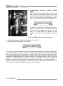
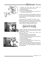
Make sure that the cold water supply line intended
for condensation has pressure values between 1
and 3 BAR and temperature between 13° and
20°C.
Connect the cold water supply pipe intended for
condensation onto the machine inlet as shown in
the figure. Use a Ø1/2” fitting and place a gate
valve in the operator's reach.
Connect the condensation water drain pipe onto
the machine outlet as shown in the figure, using a
Ø1/2” fitting.
Always use new pipes suitable for hot water and
for pressure up to 10 bars both for delivery and
draining. Never use worn or consumed piping. Use
suitable DIN 3017 hose clamps.
The drain pipe must have an inclination of at least
3 cm for each meter of length.
After having connected the water inlet and outlet
pipes, with the machine stopped, open the cut-off
cock and make sure that water does not leak from
the drain.
Turn off the master switch and press the
PRODUCTION button to check the following:
1. Beater motor rotation direction (three-phase
models only).
The machine is equipped with a sophisticated
electronic system which is able to automatically
detect if the beater motor rotation direction is
the correct one (anti-clockwise).
If the phases are inverted in the plug, after a
few seconds of operating in production mode,
the machine stops and the display shows the
F23 alarm. To connect the phases properly cut
the power and invert the two phase wires in the
plug.

11 - ENGLISH
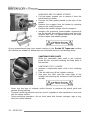
2. Condensation pressure (water models
only).
With the machine in production mode, after a
few seconds condensation water must come
out of the drain pipe at a temperature of about
35°C. If this is not the case, the pressure switch
valve shown in the figure must be adjusted.
Three-phase machines are powered with three-
phase + neutral lines: be careful never to
connect the phase lines with neutral. TAYLOR
will not be held liable for damage to the
machine deriving from incompliance with this
rule.
Press the STOP button to stop the machine .
Operating temperature should be between 15° and 35°C.
Humidity should be between 30 and 60%.
TAYLOR will not be held liable for personal harm and/or damage to objects deriving from
incorrect installation and/or by failure to comply with work accident-prevention standards.
Never intervene on the machine with your hands, neither during normal operating cycles
nor during cleaning and maintenance, without first having stopped the machine by
pressing the STOP button and having turned off the master switch. Never clean the
appliance using a high-pressure water jet. Never shut the water cut-off cock while the
machine is running. Be careful never to damage the power cable. If so, have it replaced.
Machines with water cooling which are left in places at a temperature below or close to
0°C, must first have all the water drained from the condenser.

ENGLISH - 12
5. SAFETY DEVICES
Shearing-prevention safety device: Implemented by means of a safety circuit compliant
with the European directive, it intervenes when the door is opened and/or when the safety
grid on the hopper is lifted, temporarily switching the machine to STOP mode.
Beater motor overheating safety device: Implemented by means of a thermal relay; it
protects the machine beater motor operation from overloads, by signalling the relative
alarm message on the display, emitting an intermittent acoustic signal and enabling to
reset directly from the push button control panel.
Semi-hermetic compressor motor overheating safety device: Implemented by means
of an automatic reset thermal relay; it protects the machine compressor motor operation
from overloads, by signalling the relative alarm message on the display, emitting an
intermittent acoustic signal and enabling to reset directly from the push button control
panel.
Hermetic compressor motor overheating safety device: Implemented by means of an
automatic reset thermal-current sensor; it protects the machine compressor motor
operation from overloads. The protection device intervention determines the temporary
stop of the compressor motor only.
Refrigeration circuit over-pressure safety device: Implemented by means of the
approved automatic-reset safety pressure switch; it protects the integrity of the
refrigeration circuit from over-pressure. The protection device intervention determines the
temporary stop of the compressor motor only.
Protection against short circuit of auxiliary utilities: Implemented by fuses which
intervene on the logic unit or auxiliary power supply in the event of short-circuits.
SELV safety circuit: the push button control panel is powered at low voltage by means of
an approved dual-insulation safety transformer, protected against short circuits by fuses.

13 - ENGLISH
6. OPERATION
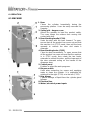
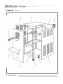
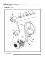
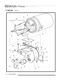
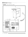
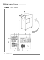
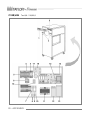
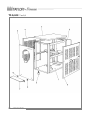
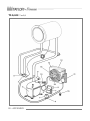
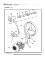
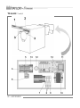
6.1 MACHINE
1. Door
Closes the cylinder hermetically during the
processing phases. It can be easily removed for
cleaning.
2. Safety grid – hopper cover
Allows the operator to load the product safely.
The cover keeps the mixture from coming into
contact with dust.
3. Door blocking handle (C119)
Seals the door with the lever lowered. To open,
ensure that all the product has come out and that
the machine is in STOP mode, then pull the lever
upwards to unblock the door and rotate it
outwards.
4. Door blocking knobs (C122)
Close the door hermetically. To open, ensure that
all the product has come out and that the machine
is in STOP mode, then rotate the two knobs
outwards to unblock the door, pull the lower part of
the door outwards acting on the handle of the
dispenser door.
5. Control panel
Enables to select the work programs.
6. Dispenser disk
Used when extracting ice cream and emptying
water to clean the cylinder. It is unblocked by
rotating it to the right (C119) or to the left (C122).
7. Drip drawer
Collects leakage of liquid from the cylinder gland
follower.
8. Electrical box
9. Water / electrical power inputs

ENGLISH - 14
6.2 CONTROLS
DISPLAY
Displays the information relative to work programs and allowed
adjustments.
LED
The LED switches on to signal when the door is opened, when the
safety grid is lifted or any anomalies of the system.
STOP
In whatever operating phase the machine is in, pressing the STOP
key stops the machine and cancels the function in progress. Do not
stop the machine when the ice cream is close to its maximum
consistency, during the automatic or semi-automatic cycles. This
precaution lengthens the life of the transmission belt and of the
beater motor.
EXTRAZIONE/ UP (EXTRACTION/ UP)
This key has several functions:
1. With the machine in STOP mode, by pressing the
EXTRACTION/UP key only the beater motor is started.
In any other operative phase of the machine, pressing the
EXTRACTION/UP key only the beater motor keeps running and
the compressor stops. Press the STOP key to stop mixing.
2. During programming, by pressing the EXTRACTION/UP key, it is
possible to scroll the menu entries or to increase the value of the
selected parameter.
PRODUZIONE/CONFERMA (PRODUCTION/CONFIRM)
This key has several functions:
1. AUTOMATIC CYCLE
With the machine in STOP mode, by pressing the PRODUCTION
key the automatic cycle starts that enables to reach the best
possible compromise between freezing time and ice cream
consistency, regardless of the type of mixture used, provided that
they are within the minimum and maximum capacity of the
appliance.
2. AUTOMATIC HARD CYCLE
With the machine in automatic cycle, by pressing the
PRODUCTION key again it is possible to access the automatic
Hard cycle, that enables to reach the optimal level of ice cream
batch freezing, regardless of the type of mixture used, provided
that they are within the minimum and maximum capacity of the
appliance.

15 - ENGLISH
3. SEMI-AUTOMATIC CYCLE with consistency control.
With the machine in automatic Hard cycle, by pressing the
PRODUCTION key again it is possible to access the semi-
automatic cycle with consistency control that enables the operator
to manually select the level of consistency one wishes to achieve.
4. During programming, pressing the PRODUCTION/CONFIRM key
confirms the selection of the menu entry or the value of the
selected parameter.
SEMI-AUTOMATIC TIME/DOWN CYCLE
This key has several functions:
1. SEMI-AUTOMATIC CYCLE with time control.
With the machine in STOP mode, by pressing the SEMI-
AUTOMATIC TIME/DOWN CYCLE key it is possible to access
the batch freezing time control, which enables the operator to
manually select the processing time of the mixture.
2. During programming, by pressing the SEMI-AUTOMATIC
TIME/DOWN CYCLE key it is possible to scroll the menu entries
or to reduce the value of the selected parameter.
SLUSH PRODUCTION
With the machine in STOP mode, by pressing the SLUSH
PRODUCTION key one enables the GR1 programs with consistency
control and continuous mixing, and GR2 with time control and cyclic
mixing.

ENGLISH - 16
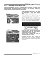
6.3 ICE CREAM AND SLUSH PRODUCTION
After having installed the machine in compliance with the instructions of chapter 3 and
having accurately washed and sanitised it, according to the instructions contained in
chapter 7, proceed as follows to start ice cream making:
- Make sure that the gate valve of cold water
for condensation is open (water models
only).
- Make sure the master switch is closed and
that the machine is powered correctly.
- Check that the door dispenser disk is
assembled properly and in closed position.
- Lift the hopper lid and pour the mixture in the
loading hopper, strictly observing the
minimum and maximum amounts admitted
per cycle and carried on the following table:
Model
MIN (kg)
MAX (kg)
C119
1
4
C122
1
3
Failure to comply with the minimum and
maximum load values can entail machine
malfunctioning and even breakage.
Minimum loads of mixture may entail the
premature wear of the scrapers.
- Reposition the hopper lid in its place to
prevent that, during processing, dust and
other impurities may come into contact with
the product.

17 - ENGLISH
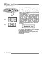
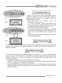
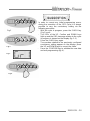
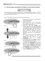
6.3.1 AUTOMATIC CYCLE
- Press the PRODUCTION key to start the
automatic batch freezing cycle. (Fig. 1)
- The AUT message is viewed on the display for a
few seconds to confirm the automatic cycle has
been selected (Fig. 2); subsequently, during batch
freezing, the instantaneous consistency numerical
value is displayed.(Fig. 3).
- After a few minutes and once the best possible
compromise between batch freezing time and
consistency has been reached, depending on the
type and amount of mixture introduced, an
intermittent acoustic signal warns the operator that
it is possible to extract the ice cream. If this should
not be immediately possible, the machine will
automatically see to maintain the ice cream over
time without changing its consistency any further.
- It is possible to go to the product extraction phase
at any time.
The automatic batch freezing cycle is particularly
recommended in the following cases:
- Mixtures with medium-low content of sugar and fat
- Water-based fruit mixtures
- Low amounts
Fig.2
Fig.3

ENGLISH - 18
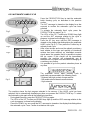
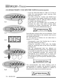
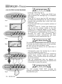
6.3.2 AUTOMATIC HARD CYCLE
- Press the PRODUCTION key to start the automatic
batch freezing cycle, as described in the previous
section.
- The AUT message is viewed on the display for a few
seconds to confirm the automatic cycle has been
selected
- To activate the automatic Hard cycle, press the
PRODUCTION key again (Fig. 1).
- The LEDs of the UP, Confirm and DOWN keys light
up and the AUT message relative to the cycle in
progress is viewed on the display. (Fig. 2-3)
- Press the UP key once until the HRD message is
viewed on the display that distinguishes the automatic
HARD cycle (Fig. 4-5). Then press the Confirm key to
activate a new cycle.
- After a few minutes and once the optimal consistency
level relative to the type and quantity of introduced
mixture has been reached, an intermittent acoustic
signal warns the operator that it is possible to extract
the ice cream. If this should not be immediately
possible, the machine will automatically see to
maintain the ice cream over time without changing its
consistency any further.
- It is possible to go to the product extraction phase at
any time.
The automatic HARD batch freezing cycle is
particularly recommended in the following cases:
- Mixtures with high content of sugar and fat
- Milk and/or alcohol-based cream mixtures
- High amounts
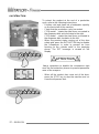
The machine stores the last program selected in its memory. If the HARD cycle has been
selected, this is automatically recalled every time one presses the PRODUCTION key. To select
the Automatic cycle again refer to the following instructions:
- During batch freezing, press the PRODUCTION key again.
- The LEDs of the UP, Confirm and DOWN keys light up and the HRD message relative to the
cycle in progress is viewed on the display.
- Press the DOWN key once until the AUT message is viewed on the display that distinguishes
the automatic cycle. Press Confirm to activate a new cycle.
Fig.1
Fig.2
Fig.3
Fig.4
Fig.5

19 - ENGLISH
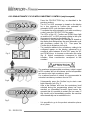
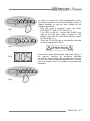
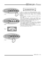
6.3.3 SEMI-AUTOMATIC CYCLE WITH CONSISTENCY CONTROL (only for experts)
- Press the PRODUCTION key, as described in the
previous sections.
- The AUT or HRD message is viewed on the display
for a few seconds to confirm the automatic or
automatic HARD cycle has been selected.
- To activate the semi-automatic cycle with consistency
control, press the PRODUCTION key again.
- The LEDs of the UP, Confirm and DOWN keys light
up and the AUT or HRD message relative to the cycle
in progress is viewed on the display (fig. 1).
- Press the UP key until the SAC message is viewed on
the display that distinguishes the semi-automatic cycle
with consistency control. (fig. 2-3). Then press the
Confirm key to activate a new cycle.
- The numbers relative to the consistency setting to be
configured appear on the display, expressed by a
numerical value between 60 and 250: press the UP
and DOWN keys to increase or decrease this value
(fig. 4). Higher consistencies correspond to high
numbers, lower consistencies correspond to low
numbers.
The maximum programmable consistency value is equal
to 250 numbers but not all mixtures and not all quantities
can reach such a high consistency value.
For a reduced amount of mixture it is recommended to
not select consistency numbers close to 250.
- Subsequently, press the Confirm key to start a new
batch freezing cycle (Fig. 5).
- After a few minutes and once the consistency level
selected during the programming phase has been
reached, an intermittent acoustic signal warns the
operator that it is possible to extract the ice cream. If
this should not be immediately possible, the machine
will automatically see to maintain the ice
- It is possible to go to the product extraction phase
at any time.
Fig.1
Fig.2
.
Fig.3
Fig.4
Fig.5
La pagina si sta caricando...
La pagina si sta caricando...
La pagina si sta caricando...
La pagina si sta caricando...
La pagina si sta caricando...
La pagina si sta caricando...
La pagina si sta caricando...
La pagina si sta caricando...
La pagina si sta caricando...
La pagina si sta caricando...
La pagina si sta caricando...
La pagina si sta caricando...
La pagina si sta caricando...
La pagina si sta caricando...
La pagina si sta caricando...
La pagina si sta caricando...
La pagina si sta caricando...
La pagina si sta caricando...
La pagina si sta caricando...
La pagina si sta caricando...
La pagina si sta caricando...
La pagina si sta caricando...
La pagina si sta caricando...
La pagina si sta caricando...
La pagina si sta caricando...
La pagina si sta caricando...
La pagina si sta caricando...
La pagina si sta caricando...
La pagina si sta caricando...
La pagina si sta caricando...
La pagina si sta caricando...
La pagina si sta caricando...
La pagina si sta caricando...
La pagina si sta caricando...
La pagina si sta caricando...
La pagina si sta caricando...
La pagina si sta caricando...
La pagina si sta caricando...
La pagina si sta caricando...
La pagina si sta caricando...
La pagina si sta caricando...
La pagina si sta caricando...
La pagina si sta caricando...
La pagina si sta caricando...
La pagina si sta caricando...
La pagina si sta caricando...
La pagina si sta caricando...
La pagina si sta caricando...
La pagina si sta caricando...
La pagina si sta caricando...
La pagina si sta caricando...
La pagina si sta caricando...
La pagina si sta caricando...
La pagina si sta caricando...
-
 1
1
-
 2
2
-
 3
3
-
 4
4
-
 5
5
-
 6
6
-
 7
7
-
 8
8
-
 9
9
-
 10
10
-
 11
11
-
 12
12
-
 13
13
-
 14
14
-
 15
15
-
 16
16
-
 17
17
-
 18
18
-
 19
19
-
 20
20
-
 21
21
-
 22
22
-
 23
23
-
 24
24
-
 25
25
-
 26
26
-
 27
27
-
 28
28
-
 29
29
-
 30
30
-
 31
31
-
 32
32
-
 33
33
-
 34
34
-
 35
35
-
 36
36
-
 37
37
-
 38
38
-
 39
39
-
 40
40
-
 41
41
-
 42
42
-
 43
43
-
 44
44
-
 45
45
-
 46
46
-
 47
47
-
 48
48
-
 49
49
-
 50
50
-
 51
51
-
 52
52
-
 53
53
-
 54
54
-
 55
55
-
 56
56
-
 57
57
-
 58
58
-
 59
59
-
 60
60
-
 61
61
-
 62
62
-
 63
63
-
 64
64
-
 65
65
-
 66
66
-
 67
67
-
 68
68
-
 69
69
-
 70
70
-
 71
71
-
 72
72
-
 73
73
-
 74
74


Frigomat Taylor C122 03 Series Operating
- Categoria
- Fabbricatori di cubetti di ghiaccio
- Tipo
- Operating
- Questo manuale è adatto anche per
in altre lingue
- English: Frigomat Taylor C122 03 Series
Altri documenti
-
Taylor C117 Manuale utente
-
Taylor Model 430 Manuale del proprietario
-
Nilfisk 3151 Manuale del proprietario
-
-
Crathco Manual Manuale utente
-
-
-
-
-
Hobart Smartronic SADL Installation And Operation Instructions Manual