Lindy 4 Port HDMI Processor Switch Manuale utente
- Categoria
- Interruttori video
- Tipo
- Manuale utente

© LINDY Group - THIRD EDITION
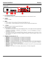
HDMI 4x1 PiP Video Processor
User Manual English
Benutzerhandbuch Deutsch
Manuel Utilisateur Français
Manuale Italiano
No. 38130
lindy.com
Tested to Comply with
FCC Standards
For Home and Office Use!


User Manual English
Introduction
Thank you for purchasing the Lindy HDMI 4x1 PiP Video Processor. This product has been designed to
provide trouble free, reliable operation. It benefits from both a LINDY 2 year warranty and free lifetime
technical support. To ensure correct use, please read this manual carefully and retain it for future
reference.
The PiP Video Processor allows the signals from four different sources to be integrated for display on a
single monitor, for viewing in Multi-View, Picture in Picture, Overlay (Chromakey) layouts.
This flexible feature rich product has been designed to be used in a number of different applications, such
as:
Public Advertisement
Digital Presentation
Broadcasting & Control
CCTV, Surveillance & Control
Conference & Meeting Room
Package Contents
HDMI 4x1 PiP Video Processor
IR Remote Control
Multi-Country 12V 3A Power Supply (UK/EU/US/AUS)
Driver CD
This manual
Features
Allows 4 HDMI Inputs to be shown on a single HD displays in 4 modes
PiP Mode: Picture in Picture
Multi-Window Mode: View 2 – 4 Inputs simultaneously
Overlay Mode: Picture On Picture with Chromakey
Seamless switching between HDMI sources
User definable channel size and position adjustment
Independent audio selection
Controlled via On-panel controls, IR Remote, RS-232 and Telnet
Adjustable picture contrast, brightness, saturation and hue
Memory function to store 4 user determined configurations
Can be used with LINDY HDMI extenders to reach a remote display
Specification
Input ports: 4 x HDMI Female
Input resolution: 480i – 1080p
Output ports: 1 x HDMI Female
Output resolution: 1080p
Audio support: LPCM 2CH, 6CH, 8CH, AC3, DTS, Dolby Digital Plus, Dolby TrueHD & DTS-HD
Control Ports: RJ45 (Telnet) & Serial 9 Way Male (RS-232)
Video bandwidth: 225MHz/6.75Gbps
Power consumption: 15W
Weight: 2.95 kg
Dimensions: 436x247x44mm (WxDxH)

User Manual English
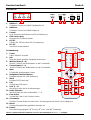
Overview & Operation
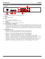
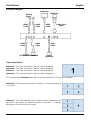
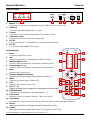
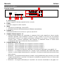
Front Panel
1. IR Window
Receives IR commands from the supplied IR Remote
2. Power
Turn the Switch On/Off
3. Menu
Press to launch the OSD menu
Press to make a menu selection in the OSD
4. -/+ Buttons
Use these buttons to move up and down in the OSD
5. Channel Input (1 – 4) Selection
Use the Channel Input buttons to cycle through the available Inputs for each Channel; use Input
Channel button 1 to control Channel 1, Input Channel button 2 to control Channel 2 and so on. For
example if you have selected Channel 1, by default this will display Input 1, by pressing Channel
Input button 1 the Input will switch to Input 2, further presses will move the Input to 3 to 4 and then
back to 1.
6. Window Mode (A – H)
Window A – Only the Input selected under Channel 1 will be displayed.
Window B – Only the Input selected under Channel 2 will be displayed.
Window C – Only the Input selected under Channel 3 will be displayed.
Window D – Only the Input selected under Channel 4 will be displayed.
Window E – The Inputs selected under Channels 1 – 4 will be displayed in a 2 x 2 grid.
Window F – The Input selected under Channel 4 will be displayed on the right half of the screen,
the Inputs selected for Channels 1 – 3 will be displayed in on the left half of the screen.
Window G – The Input selected under Channel 1 will be displayed full screen, with the Inputs
selected under Channels 2 – 4 will show (Picture in Picture) across the bottom of the screen.
Window H – the Inputs selected under Channels 1 – 4 will be displayed in a 4 x 1 grid.
POWER
MENU
-
+
CHANNEL
INPUT
1
2
3
4
G/
H/
WINDOW
A/1
B/2
C/3
D/4
E/
F/
1
2
3
5
6
4

User Manual English
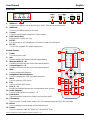
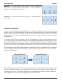
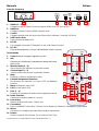
Rear Panel
1. HDMI In 1 – 4
Connect your HDMI sources devices such as PC, Blu-ray etc to these ports
2. HDMI Out
Connect your HDMI display to this port
3. Control
Connect to an Ethernet network for Telnet control
4. USB Service Only
Reserved for Factory use only
5. RS-232
For connection to a PC/Notebook or Remote Control Processing unit
6. DC 12V
Connect the supplied 12V power supply here
Remote Control
1. Power
Turn the Switch on/off
2. Info
Press to display the Switch’s current output setting
3. Window Mode (A – H)
Provides the same function as the front panel buttons
4. Channel Input (1 – 4)
Provides the same function as the front panel buttons
5. Mute
Press to Mute audio playback
6. Navigation/Selection Buttons
Press to navigate the OSD and make selections
7. Menu
Press to enter the OSD menu
8. Exit
Press to exit the OSD menu
9. FAV. (1 – 4)
Recalls the settings saved to the corresponding save location
10. Audio Selection
Press to select audio from Inputs 1 – 4
11. Fade In/Out
Press this button to switch the Fade-in-out function on/off
12. Chromakey*
Press to enter Chroma mode, where CH1 is the background and CH2 is the top image
13. Mirror*
Press to display a mirror image of the selected input
14. Rotate*
Press to rotate the input: 90
0
Right, 90
0
Left and 180
0
(Flip)
*These features are only available in Window modes A – D
Input
INFO
POWER
WA
WE
CH 1
WF
CH 2
WG
CH 3
WH
CH 4
Mute
OK
Exit
Menu
Audio 1
Fade In/Out
FAV.1
Audio 2
Chromakey
FAV.2
Audio 3
Mirror
FAV.3
FAV.4
Rotation
Audio 4
WB
WC
WD
10
9
1
2
3
4
5
6
8
7
11
12
13
14
HDMI IN
1
2
3
4
HDMI OUT
CONTROL
RS232
DC 12V
USB
SERVICE
ONLY
2
3
4
5
6
1

User Manual English
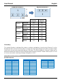
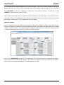
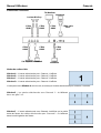
Connection Diagram
Video Output Modes
Window A – The Input selected for Channel 1 will be displayed.
Window B – The Input selected for Channel 2 will be displayed.
Window C – The Input selected for Channel 3 will be displayed.
Window D – The Input selected for Channel 4 will be displayed.
The example shows Window A selected, so the Input selected for Channel 1 is displayed.
Window E – The Inputs selected under Channels 1 – 4 will be displayed in
a 2 x 2 grid.
Window F – The Input selected under Channel 4 will be displayed on the
right half of the screen, the Inputs selected for Channels 1 – 3 will be
displayed in on the left half of the screen.
Set-Top Box
Blu-Ray
Player
HDMI
Cable
9 Way Serial
Cable
HDMI
Cable
HDMI
Cable
HDMI
Cable
HDMI
Cable
Notebook
Notebook
Notebook
TV/Monitor
RJ45
Cable

User Manual English
Window G – The Input selected under Channel 1 will be displayed full
screen, with the Inputs selected under Channels 2 – 4 will show (Picture in
Picture) across the bottom of the screen.
Window H – the Inputs selected under Channels 1 – 4 will be displayed in
a 4 x 1 grid.
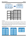
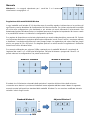
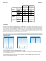
Multi-Window Adjustment
In each of the multi-window options (E-H) above it is possible to adjust the size and position of each
window, and even to switch windows off. To begin select the window option which is closest to your desired
layout and then enter the menu using the remote control. Now select Windows Setup and you will be
presented with the choice to adjust each Channel 1-4 and the option to Store or Recall Favourites
configurations.
To adjust the layout begin by selecting a channel, by highlighting one of the channels and pressing OK.
You can then adjust the vertical and horizontal size and position of the window using the Size and Position
menu options, whilst you can turn the channel on or off using the Image Output menu. Adjustments can
be made in single pixel, ten pixel and one hundred pixel blocks giving you absolute control of the window;
if you make an error you can quickly return to the default value for the window by selecting Window Reset.
As an example using a 1080p display starting with Window E selected, by adjusting the size of channels
1 and 3 to 1920 pixels wide by 540 pixels high and turning off the output of channels 2 and 4 you would
achieve the layout below.
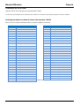
When adjusting the position of a channel the horizontal position is from left to right of the display, starting
from the left edge of the channel. The vertical position is from top to bottom of the display, starting at the
top edge of the channel. The following example shows the default layout for each channel in Window G
and an adjusted version made by changing the values of each channel.
Standard Window E
Adjusted Window E

User Manual English
Standard
Adjusted
Channel 1
Horizontal
0000
0000
Vertical
0000
0000
Channel 2
Horizontal
0105
0210
Vertical
0700
0120
Channel 3
Horizontal
0710
0710
Vertical
0700
0120
Channel 4
Horizontal
1315
1210
Vertical
0700
0120
Chromakey
This special function is designed for picture on picture overlapping. It works using Channel 1 as the
background and Channel 2 as the top layer. Channel 2 the top layer's background colour is usually a single
colour which can be easily removed using the OSD Menu. The RGB settings for Channel 2 video can be
adjusted to determine where the layer will be transparent making Channel 1 visible. When input 1 or 2 has
no source connection a warning message will appear on OSD.
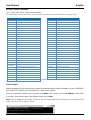
RS-232, Telnet & OSD Control
RS-232 Protocols
HDMI PiP Switch
Remote Control
PIN
Assignment
PIN
Assignment
Baud Rate
115200bps
1
NC
1
NC
Data Bit
8
2
Tx
2
Rx
Parity
None
3
Rx
3
Tx
Flow Control
None
4
NC
4
NC
Stop Bit
1
5
GND
5
GND
6
NC
6
NC
7
NC
7
NC
8
NC
8
NC
9
NC
9
NC
Standard Window G
0
1920
0
1080
0
Adjusted Window G

User Manual English
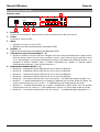
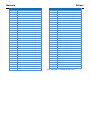
RS-232 & Telnet Commands
Use TCP/IP (Port 23) for Telnet communication.
All commands are case–sensitive and will not be executed unless followed with a carriage return
Command
Action
Command
Action
POW000
OFF
FAD001
Fade In-Out On
POW001
ON
AUD001
Change Output Audio to Source 1
WND001
Change to Window A
AUD002
Change Output Audio to Source 2
WND002
Change to Window B
AUD003
Change Output Audio to Source 3
WND003
Change to Window C
AUD004
Change Output Audio to Source 4
WND004
Change to Window D
CHR000
Chromakey Function Off
WND005
Change to Window E
CHR001
Chromakey Function On
WND006
Change to Window F
MIR000
Mirror Function Off
WND007
Change to Window G
MIR001
Mirror Function On
WND008
Change to Window H
ROT000
Rotation Function Off
CH1001
Change Channel 1 to Source 1
ROT001
Rotation Function R
CH1002
Change Channel 1 to Source 2
ROT002
Rotation Function L
CH1003
Change Channel 1 to Source 3
ROT003
Rotation Function Up-Side Down
CH1004
Change Channel 1 to Source 4
SFA001
Store window format to FAV 1*
CH2001
Change Channel 2 to Source 1
SFA002
Store window format to FAV 2*
CH2002
Change Channel 2 to Source 2
SFA003
Store window format to FAV 3*
CH2003
Change Channel 2 to Source 3
SFA004
Store window format to FAV 4*
CH2004
Change Channel 2 to Source 4
RFA001
Recall window from FAV 1
CH3001
Change Channel 3 to Source 1
RFA002
Recall window from FAV 2
CH3002
Change Channel 3 to Source 2
RFA003
Recall window from FAV 3
CH3003
Change Channel 3 to Source 3
RFA004
Recall window from FAV 4
CH3004
Change Channel 3 to Source 4
IO1000
Channel 1 Image Off
CH4001
Change Channel 4 to Source 1
IO1001
Channel 1 Image On
CH4002
Change Channel 4 to Source 2
IO2000
Channel 2 Image Off
CH4003
Change Channel 4 to Source 3
IO2001
Channel 2 Image On
CH4004
Change Channel 4 to Source 4
IO3000
Channel 3 Image Off
MUT000
Mute Off
IO3001
Channel 3 Image On
MUT001
Mute On
IO4000
Channel 4 Image Off
FAD000
Fade In-Out Off
IO4001
Channel 4 Image On
FAD000
Fade In-Out Off
* Cannot be executed when Window A – D are selected
Telnet Control
Before attempting to use telnet control, please ensure that both the Video Processor (via the ‘CONTROL’
port) and the PC/Laptop are connected to the same active network.
Open a Command Prompt on your computer type telnet, then a space, then the IP address of the Video
Processor, then another space, then 23 and finally press Enter.
Note: The IP address of the Video Processor can be found under Ethernet Setup
on the device’s OSD
menu. 23 is the TCP/IP port for Telnet.

User Manual English
This will bring up the Telnet interface for the Video Processor. Type ? to list all the available commands,
please refer to the RS-232 & Telnet Commands section of this manual for a description of each command.
Type IPCONFIG to show the complete IP configuration of the Video Processor. To reset the IP, type
IPMODE to switch between Static IP/DHCP.
Note: All the commands will be not executed unless followed by a carriage return. Commands are case-
insensitive. If the IP is changed then the IP Address required for Telnet access will also need to be change
accordingly. A power cycle is also required for every IP change.
Web GUI Control
On a PC/Laptop that is connected to the same active network as the Video Processor, open a web browser
and type the device’s IP address on the web address entry bar. The browser will display the device’s Image
Adjust, Output Resolution... etc, as shown below. Using this interface you can control the Video processor
in just the same way as with the OSD, RS-232 and Telnet Controls.
Click on the Ethernet tab to reset the IP configuration. The system will ask for a reboot of the device
every time any of the settings are changed. The IP address needed to access the Web GUI control will
also need to be changed accordingly on the web address entry bar.

User Manual English
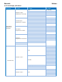
On-Screen-Display (OSD) Menu
Main Menu
1
st
Layer
2
nd
Layer
3
rd
Layer
Image Adjust
Brightness Adjust
CH 1
0 – 100 (50)
CH 2
0 – 100 (50)
CH 3
0 – 100 (50)
CH 4
0 – 100 (50)
Value Reset
Menu Exit
Contrast Adjust
CH 1
0 – 100 (50)
CH 2
0 – 100 (50)
CH 3
0 – 100 (50)
CH 4
0 – 100 (50)
Value Reset
Menu Exit
Hue Adjust
CH 1
0 – 100 (50)
CH 2
0 – 100 (50)
CH 3
0 – 100 (50)
CH 4
0 – 100 (50)
Value Reset
Menu Exit
Saturation
CH 1
0 – 100 (50)
CH 2
0 – 100 (50)
CH 3
0 – 100 (50)
CH 4
0 – 100 (50)
Value Reset
Menu Exit
Picture Reset
Menu Exit
Window Setup
Channel 1 Select
Size
CH 1 Wxxx Hxxx
Width Unit
Width Ten
Width Hundred
Height Unit
Height Ten
Height Hundred
Position
CH 1 Wxxx Hxxx
Horizontal Unit
Horizontal Ten
Horizontal Hundred
Vertical Unit
Vertical Ten
Vertical Hundred
Image Output On/Off
Window Reset
Menu Exit
Channel 2 Select
Size
CH 2 Wxxx Hxxx
Width Unit
Width Ten
Width Hundred
Height Unit
Window Setup
Chanel 2 Select
Height Ten

User Manual English
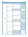
Main Menu
1
st
Layer
2
nd
Layer
3
rd
Layer
(Continued)
(Continued)
Height Hundred
Position
CH 2 Wxxx Hxxx
Horizontal Unit
Horizontal Ten
Horizontal Hundred
Vertical Unit
Vertical Ten
Vertical Hundred
Image Output On/Off
Window Reset
Menu Exit
Channel 3 Select
Size
CH 3 Wxxx Hxxx
Width Unit
Width Ten
Width Hundred
Height Unit
Height Ten
Height Hundred
Position
CH 3 Wxxx Hxxx
Horizontal Unit
Horizontal Ten
Horizontal Hundred
Vertical Unit
Vertical Ten
Vertical Hundred
Image Output On/Off
Window Reset
Menu Exit
Channel 4 Select
Size
CH 4 Wxxx Hxxx
Width Unit
Width Ten
Width Hundred
Height Unit
Height Ten
Height Hundred
Position
CH 4 Wxxx Hxxx
Horizontal Unit
Horizontal Ten
Horizontal Hundred
Vertical Unit
Vertical Ten
Vertical Hundred
Image Output On/Off
Window Reset
Menu Exit
FAV. Store
FAV 1 Store On/Off/OK
FAV 2 Store On/Off/OK
FAV 3 Store On/Off/OK
FAV 4 Store On/Off/OK
Window Setup
FAV. Recall
FAV 1 Recall On/Off/OK

User Manual English
Main Menu
1
st
Layer
2
nd
Layer
3
rd
Layer
(Continued)
FAV 2 Recall On/Off/OK
FAV 3 Recall On/Off/OK
FAV 4 Recall On/Off/OK
Menu Exit
Window Convert
Channel 1 Convert
Mirror On/Off
Fade In-Out On/Off
Rotation R90/L90/Up-side Down 180/Off
Window Reset
Menu Exit
Channel 2 Convert
Mirror On/Off
Fade In-Out On/Off
Rotation R90/L90/Up-side Down 180/Off
Window Reset
Menu Exit
Channel 3 Convert
Mirror On/Off
Fade In-Out On/Off
Rotation R90/L90/Up-side Down 180/Off
Window Reset
Menu Exit
Channel 4 Convert
Mirror On/Off
Fade In-Out On/Off
Rotation R90/L90/Up-side Down 180/Off
Window Reset
Menu Exit
Chromakey Setup
Minimum for R 000 - 255
Maximum for R 000 – 255
Minimum for G 000 - 255
Maximum for G 000 – 255
Minimum for B 000 - 255
Maximum for B 000 – 255
Switch On/Off
Menu Exit
Ethernet Setup
IP Mode
Static/DHCP
Static Set
IP/Mask/Gate
Byte 1 High
XXX
000 – 255
Byte 2
XXX
000 – 255
Byte 3
XXX
000 – 255
Byte 4
XXX
000 – 255
Re-Link
Yes/No
Exit
Static/DHCP IP
Linked/Not Linked
IP
IP/Mask/Gate
Mask
XXX.XXX.XXX.XXX
Gate
XXX.XXX.XXX.XXX
Mac
XXX.XXX.XXX.XXX
Sys Reset
Yes/No
Information
FW/Version
Menu Exit

Benutzerhandbuch Deutsch
Einführung
Wir freuen uns, dass Ihre Wahl auf ein LINDY-Produkt gefallen ist und danken Ihnen für Ihr Vertrauen.
Sie können sich jederzeit auf unsere Produkte und einen guten Service verlassen. Dieser 4 Port HDMI-
Prozessor-Switch inklusive PiP unterliegt einer 2-Jahres LINDY Herstellergarantie und lebenslangem
kostenlosen technischen Support. Bitte lesen Sie diese Anleitung sorgfältig und bewahren Sie sie auf.
Er ist weitestgehend frei konfigurierbar und biete eine Vielzahl von Darstellungsoptionen. Er unterstützt
die Quadranten-Darstellung, die Bild-in-Bild (PiP – Picture in Picture) sowie Overlay Green-Boxing
(Chromakey) Darstellung.
Mit seiner Flexibilität ist er ideal geeignet in den Bereichen Public Advertising, Digitale Präsentationen,
Video Broadcasting und Steuerung, CCTV Überwachung sowie Konferenzraumsteuerung.
Lieferumfang
HDMI 4x1 PiP Video Prozessor
IR Fernbedienung
Netzteil Multi-Country 12V 3A (mit Steckervorsätzen für UK/EU/US/AUS)
Software CD
Dieses Handbuch
Eigenschaften
Erlaubt 4 HDMI Eingänge auf einem HDMI Display in 4 unterschiedlichen Modi auszugeben:
PiP Modus: Bild-in-Bil / Picture in Picture
Multi-Window Modus: 2 – 4 Eingänge simultan anzeigen
Overlay Modus: Bild über Bild mit Chromakey Überlagerung
Unterbrechungsloses Umschalten zwischen HDMI Quellen
Benutzer definierbare Fenstergröße und -position
Unabhängige Auswahl des Audiokanales
Steuerbar über auf Tasten am Switch, IR-Fernbedienung, RS-232 und Telnet
Einstellbarer Kontrast, Helligkeit, Sättigung und Farbton
Speicherplätze zum Speichern von 4 Benutzereinstellungen
Kann mit LINDY HDMI Extendern verwendet werden
Spezifikationen
Eingangsanschlüsse: 4 x HDMI Buchse
Eingangsauflösung: 480i – 1080p
Ausgangsanschlüsse: 1 x HDMI Buchse
Ausgangsauflösung: 1080p
Audio-Unterstützung: LPCM 2CH, 6CH, 8CH, AC3, DTS, Dolby Digital Plus, Dolby TrueHD & DTS-HD
Fernbedienungseingänge: RJ45 (Telnet) & serieller 9-Pol (RS-232) Anschlussstecker
Video-Bandbreite: 225MHz / 6.75Gbps
Leistungsaufnahme: ca. 15W
Gewicht: ca. 3 kg
Abmessungen: ca. 436x247x44mm (BxTxH)

Benutzerhandbuch Deutsch
Installation
Frontansicht
1. IR Fernbedienungsfernster
Der Empfänger für die IR Fernbedienungssignale befindet sich hinter diesem Fenster
2. POWER
EIN/AUS-Schalter
3. MENU
Druck auf diese Taste ruft das OSD Menü auf dem Bildschirm auf
Druck auf diese Taste bei geöffnetem OSD Menü wählt den aktuellen Menüpunkt aus
4. -/+ Tasten
Navigationstasten für Bedienung des OSD Menüs
5. Channel Input (1 – 4) Tasten
Verwenden Sie die Channel Input / Kanal-Eingangs-Tasten, um für jeden Kanal den zugehörigen
Eingangsport festzulegen; verwenden Sie Kanaltaste 1 um den Eingangsport für Kanal 1
festzulegen, 2 für 2, usw.
Zum Beispiel: für Kanal 1 wird standardmäßig der Eingang 1 angezeigt; wenn Sie die Kanal 1 Taste
erneut drücken wird Eingang 2 auf Kanal 1 gelegt, bei weiterem Drücken Eingang 3, dann 4 und
dann wieder 1.
6. WINDOW / Fenstermodus (A – H)
Window A – Nur das Eingangssignal von Eingang 1 wird angezeigt.
Window B – Nur das Eingangssignal von Eingang 2 wird angezeigt.
Window C – Nur das Eingangssignal von Eingang 3 wird angezeigt
Window D – Nur das Eingangssignal von Eingang 4 wird angezeigt
Window E – Quadranten-Darstellung - Alle 4 Eingangssignale werden als 2x2 Signal dargestellt.
Window F – Eingangssignal 4 wird auf der rechten Seite des Monitors angezeigt, die Eingänge 1
bis 3 auf der linken Seite jeweils übereinander.
Window G – Kanal 1 wird als Vollbild dargestellt, die Kanäle 2 bis 4 als PiP an der Unterseite des
Bildschirms verteilt.
Window H – Die Kanäle 1 bis 4 werden nebeneinander in 4 Fenstern dargestellt
POWER
MENU
-
+
CHANNEL
INPUT
1
2
3
4
G/
H/
WINDOW
A/1
B/2
C/3
D/4
E/
F/
1
2
3
5
6
4

Benutzerhandbuch Deutsch
Rückansicht
1. HDMI In 1 – 4
Schließen Sie hier Ihre HDMI Signalquellen an
2. HDMI Out
Schließen Sie hier Ihre HDMI Display an
3. Control
RJ45 Anschluss für Ethernet und Telnet Bedienung
4. USB Service Only
Reserviert für Firmware Update
5. RS-232
Serieller RS-232 Anschluss für Fernsteuerung
6. DC 12V
Anschluss für das Netzteil
Fernbedienung
1. Power
Switch EIN/AUS schalten
2. Info
Zeigt die aktuell gewählte Ausgabeeinstellung an
3. Window Mode (A – H)
Gleiche Funktion wie Bedientasten an der Frontblende
4. Channel Input (1 – 4)
Gleiche Funktion wie Bedientasten an der Frontblende
5. Mute
Schaltet die Audioausgabe Stumm
6. Navigation/Selection Buttons
Navigationstasten für OSD Bedienung
7. Menu
Ruft das OSSD Menü auf
8. Exit
Schließt das OSD Menü
9. FAV. (1 – 4)
Wechselt zu einer der 4 Voreinstellungen
10. Audio Selection
Wechselt zwischen den Audiokanälen 1 – 4
11. Fade In/Out
Schaltet die Fade-in-out Funktion an/aus
12. Chromakey*
Ruft den Chroma Modus auf mit Kanal 1 als Hintergrund und Kanal 2 als Vordergrund
13. Mirror*
Ruft das Spiegelbild des gewählten Kanales auf
14. Rotate*
Dreht das Eingangssignal: 90
0
Rechts, 90
0
Links und 180
0
(Überkopf)
*Die mit * gekennzeichneten Funktionen sind nur in den Einstellungen Window A – D verfügbar
Input
INFO
POWER
WA
WE
CH 1
WF
CH 2
WG
CH 3
WH
CH 4
Mute
OK
Exit
Menu
Audio 1
Fade In/Out
FAV.1
Audio 2
Chromakey
FAV.2
Audio 3
Mirror
FAV.3
FAV.4
Rotation
Audio 4
WB
WC
WD
10
9
1
2
3
4
5
6
8
7
11
12
13
14
HDMI IN
1
2
3
4
HDMI OUT
CONTROL
RS232
DC 12V
USB
SERVICE
ONLY
2
3
4
5
6
1

Benutzerhandbuch Deutsch
Anschlussdiagramm – Beispiel
Video Output Modes
Window A – Nur das Eingangssignal von Eingang 1 wird angezeigt.
Window B – Nur das Eingangssignal von Eingang 2 wird angezeigt.
Window C – Nur das Eingangssignal von Eingang 3 wird angezeigt.
Window D – Nur das Eingangssignal von Eingang 4 wird angezeigt.
Das Beispiel zeigt Window A ausgewählt, nur Eingang 1 wird angezeigt.
Window E – Die Eingänge 1 – 4 werden als 2x2 Quadranten-Darstellung
angezeigt.
Window F – Der Eingang Channel 4 wird auf der rechten Seite des
Monitors angezeigt, die Eingänge Channel 1 bis 3 auf der linken Seite
jeweils übereinander.
Set-Top Box
Blu-Ray Player
HDMI
Kabel
9 Pol RS-232
Kabel
HDMI
Kabel
HDMI
Kabel
HDMI
Kabel
HDMI
Kabel
Notebook
Notebook
Notebook
TV/Monitor
RJ45
Kabel

Benutzerhandbuch Deutsch
Window G – Eingangssignal Channel 4 wird als Vollbild dargestellt, die
Kanäle 2 bis 4 als PiP an der Unterseite des Bildschirms verteilt.
Window H – Die Eingangssignale Channels 1 – 4 werden nebeneinander
in 4 x 1 Form dargestellt.
Multi-Fenster-Einstellungen
In allen Multi-Fenster-Einstellungen (E-H) ist es möglich, die Größe und Position der einzelnen Fenster
anzupassen und sogar Fenster ausschalten. Um dies einzustellen, wählen Sie zwischen einer der
Window E-H Einstellungen, je nachdem welche am nächsten zu Ihrem gewünschten Layout ist. Rufen
Sie das OSD-Menü mit der Fernbedienung auf und wählen Sie den Fenster-Setup E-H. Wählen Sie mit
Channel 1-4 die Eingänge zu den Kanälen / Channels. Und speichern Sie Ihre Einstellung unter einem
der 4 Presets.
Beginnen Sie die Eingangssignale/-ports den Kanälen / Channels zuzuordnen: Wählen Sie einen Channel
und sehen Sie den zugehörigen Eingangsport, durch wiederholtes Drücken der Channel Taste wechseln
Sie die Eingangsports durch (siehe Vorseite), durch drücken der OK Taste speichern Sie.
Sie können dann die vertikale und horizontale Größe und Position des Fensters über die SIZE und
POSITION Menüoptionen anpassen; und sie können die Bildausgabe ein- oder ausschalten über das
IMAGE OUTPUT Menü. Anpassungen können in einzelnen Pixel, zehn Pixel- und 100 Pixel-Blöcken
erfolgen, was Ihnen die absolute Kontrolle über die Fenster gibt; Wenn Sie einen Fehler machen, können
Sie schnell auf den Standardwert für das Fenster zurückkehren, indem Sie WINDOWS RESET drücken.
Beispiel 1 (Signale mit 1080p Auflösung (1920x1080), beginnend mit der Einstellung WINDOW E):
durch Anpassen der Größe von Kanal 1 und 3 auf 1920 Pixel Breite und 540 Pixel Höhe, und deaktivieren
der Ausgabe der Kanäle 2 und 4, erhalten Sie das Layout wie unten angezeigt.
Standard Window E
Editiertes Window E

Benutzerhandbuch Deutsch
Die die horizontale Position zählt von links nach rechts auf dem Displays, ausgehend vom linken Rand
des Kanals. Die vertikale Position zählt von oben nach unten im Display, beginnend mit dem oberen Rand
des Kanals.
Das folgende Beispiel 2 zeigt das Standardlayout für Window G sowie eine editierte Version, die durch
eine Änderung der Werte jedes einzelnen Kanals erreicht wird. Es müssen hier nur die oberen linken
Eckpunkte des jeweiligen Channel 2-4 editiert werden; die Größe ist durch die WINDOW G Voreinstellung
vorbelegt und nicht verändert.
Standard
Editiert
Channel 1
Horizontal
0000
0000
Vertikal
0000
0000
Channel 2
Horizontal
0105
0210
Vertikal
0700
0120
Channel 3
Horizontal
0710
0710
Vertikal
0700
0120
Channel 4
Horizontal
1315
1210
Vertikal
0700
0120
Chromakey
Diese spezielle Funktion bezieht sich auf Bild-über-Bild Überlappungen. Es funktioniert mit Kanal 1 als
Hintergrund und Kanal 2 als der darüber liegenden Schicht. Üblicherweise hat die obere Schicht Kanal 2
in der Regel eine einzige Farbe als Hintergrundfarbe, diese kann über das OSD-Menü leicht entfernt
werden, so dass dort dann Kanal 1 sichtbar wird. Die RGB-Einstellungen für Kanal 2 Video können
angepasst werden, um festzulegen, wo Kanal 2 transparent wird und Kanal 1 sichtbar wird. Sowie Eingang
1 oder 2 hat Eingangssignal bekommt erscheint eine Warnmeldung per OSD.
Weitere Detaileinstellungen und Ethernet Telnet / RS232 / Browser/GUI Fernbedienung
Der Video Processor kann auch über Ethernet per Webbrowser oder Telnet bzw. über RS232 gesteuert
werden. Bitte beachten Sie die ausführlichen Erläuterungen und Einstellungstabellen im englischen Teil
dieses Handbuches und nehmen Sie die Einstellungen entsprechend per Fernbedienung und OSD bzw.
Browser vor.
Standard Window G
0
1920
0
1080
0
Editiertes Window G

Manuel Utilisateur Français
Introduction
Nous sommes heureux que votre choix se soit porté sur un produit LINDY et vous remercions de votre
confiance. Vous pouvez compter à tout moment sur la qualité de nos produits et de notre service. Ce
HDMI 4x1 PiP Video Processor LINDY est soumis à une durée de garantie LINDY de 2 année(s) et
d’une assistance technique gratuite à vie. Merci de lire attentivement ces instructions et de les conserver
pour future référence.
Le PiP Video Processor permet aux signaux de quatre différentes sources d’être intégrés dans l’affichage
d’un seul écran, pour une visualisation en Multi-View, Picture in Picture, Overlay (Chromakey).
Ce produit riche de fonctionnalités a été conçu pour être utilisé dans différents cas de figures et
applications, tels que:
Affichage publicitaire
Présentation numérique
Diffusion & Contrôle
CCTV, Surveillance & Contrôle
Conférence & salle de réunion
Contenu de l’emballage
HDMI 4x1 PiP Video Processor
Télécommande IR
Alimentation multi-pays 12V 3A (UK/EU/US/AUS)
CD de pilotes
Ce manuel
Caractéristiques
Allows 4 HDMI Inputs to be shown on a single HD displays in 4 modes
Mode PiP: Picture in Picture
Mode multifenêtres: affichage de 2 – 4 entrées simultanément
Mode Overlay: Picture On Picture avec Chromakey
Commutation transparente entre les sources HDMI
Taille de canal et réglage de position définissable par utilisateur
Sélection audio indépendante
Contrôlé via contrôle On-panel (boutons en façade), télécommande IR, RS-232 et Telnet
Réglage contraste, luminosité, saturation et teinte
Fonction mémorisation pour sauvegarder 4 configurations utilisateur
Peut être utilisé avec les extenders HDMI LINDY, pour atteindre un affichage déporté
Spécifications
Ports d’entrées: 4 x HDMI femelle
Résolutions en entrée: 480i – 1080p*
Ports de sortie: 1 x HDMI femelle
Résolution en sortie: 1080p
Prise en charge audio: LPCM 2CH, 6CH, 8CH, AC3, DTS, Dolby Digital Plus, Dolby TrueHD & DTS-
HD
Ports de contrôle: RJ45 (Telnet) & Série DB-9 mâle (RS-232)
Bande passante vidéo: 225MHz/6.75Gbit/s
Puissance: 15W
Poids: 2.95 kg
Dimensions: 436x247x44mm (LxlxH)
La pagina sta caricando ...
La pagina sta caricando ...
La pagina sta caricando ...
La pagina sta caricando ...
La pagina sta caricando ...
La pagina sta caricando ...
La pagina sta caricando ...
La pagina sta caricando ...
La pagina sta caricando ...
La pagina sta caricando ...
La pagina sta caricando ...
La pagina sta caricando ...
La pagina sta caricando ...
La pagina sta caricando ...
La pagina sta caricando ...
La pagina sta caricando ...
La pagina sta caricando ...
La pagina sta caricando ...
La pagina sta caricando ...
La pagina sta caricando ...
-
 1
1
-
 2
2
-
 3
3
-
 4
4
-
 5
5
-
 6
6
-
 7
7
-
 8
8
-
 9
9
-
 10
10
-
 11
11
-
 12
12
-
 13
13
-
 14
14
-
 15
15
-
 16
16
-
 17
17
-
 18
18
-
 19
19
-
 20
20
-
 21
21
-
 22
22
-
 23
23
-
 24
24
-
 25
25
-
 26
26
-
 27
27
-
 28
28
-
 29
29
-
 30
30
-
 31
31
-
 32
32
-
 33
33
-
 34
34
-
 35
35
-
 36
36
-
 37
37
-
 38
38
-
 39
39
-
 40
40


Lindy 4 Port HDMI Processor Switch Manuale utente
- Categoria
- Interruttori video
- Tipo
- Manuale utente
in altre lingue
Documenti correlati
-
Lindy 38130 Manuale utente
-
-
-
-
Lindy HDMI 4 Port Multi-View Switch Manuale utente
-
-
-