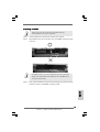
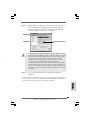
ASROCK 775XFire-RAID Manuale del proprietario
- Categoria
- Schede madri
- Tipo
- Manuale del proprietario

11
11
1
ASRock 775XFire-RAID Motherboard
EnglishEnglish
EnglishEnglish
English
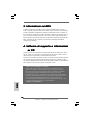
Copyright Notice:Copyright Notice:
Copyright Notice:Copyright Notice:
Copyright Notice:
No part of this installation guide may be reproduced, transcribed, transmitted, or
translated in any language, in any form or by any means, except duplication of
documentation by the purchaser for backup purpose, without written consent of
ASRock Inc.
Products and corporate names appearing in this guide may or may not be registered
trademarks or copyrights of their respective companies, and are used only for
identification or explanation and to the owners’ benefit, without intent to infringe.
Disclaimer:Disclaimer:
Disclaimer:Disclaimer:
Disclaimer:
Specifications and information contained in this guide are furnished for informational
use only and subject to change without notice, and should not be constructed as a
commitment by ASRock. ASRock assumes no responsibility for any errors or
omissions that may appear in this guide.
With respect to the contents of this guide, ASRock does not provide warranty of any
kind, either expressed or implied, including but not limited to the implied warranties or
conditions of merchantability or fitness for a particular purpose.
In no event shall ASRock, its directors, officers, employees, or agents be liable for
any indirect, special, incidental, or consequential damages (including damages for
loss of profits, loss of business, loss of data, interruption of business and the like),
even if ASRock has been advised of the possibility of such damages arising from any
defect or error in the guide or product.
This device complies with Part 15 of the FCC Rules. Operation is subject to the
following two conditions:
(1) this device may not cause harmful interference, and
(2) this device must accept any interference received, including interference that
may cause undesired operation.
ASRock Website: http://www.asrock.com
Published February 2006
Copyright©2006 ASRock INC. All rights reserved.

22
22
2
ASRock 775XFire-RAID Motherboard
EnglishEnglish
EnglishEnglish
English
Motherboard LMotherboard L
Motherboard LMotherboard L
Motherboard L
ayoutayout
ayoutayout
ayout
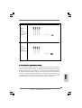
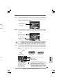
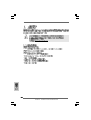
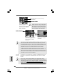
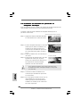
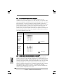
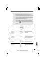
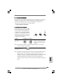
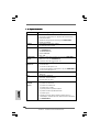
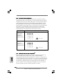
1 PS2_USB_PWR1 Jumper 16 Chassis Fan Connector (CHA_FAN1)
2 ATX 12V Connector (ATX12V1) 17 System Panel Header (PANEL1)
3 ATX Power Connector (ATXPWR1) 18 Chassis Speaker Header (SPEAKER 1)
4 775-Pin CPU Socket 19 Infrared Module Connector (IR1)
5 North Bridge Controller 20 USB 2.0 Header (USB67, Blue)
6 CPU Fan Connector (CPU_FAN1) 21 USB 2.0 Header (USB45, Blue)
7 2 x 240-pin DDRII DIMM Slots 22 Floppy Connector (FLOPPY1)
(Dual Channel A: DDRII_1, DDRII_3; Yellow) 23 Game Port Header (GAME1)
8 2 x 240-pin DDRII DIMM Slots 24 Front Panel Audio Header (HD_AUDIO1)
(Dual Channel B: DDRII_2, DDRII_4; Orange) 25 PCI Slots (PCI1- 3)
9 IDE1 Connector (IDE1, Blue) 26 BIOS FWH Chip
10 Clear CMOS Jumper (CLRCMOS1) 27 AGI Express Slot (PCI Express x 4)
11 South Bridge Controller 28 PCIEX1_EN1 - 5
12 Serial ATA Connector 2 (SATA_2, black) 29 PCI Express x 1 Slot (PCIE2)
13 Serial ATA Connector 3 (SATA_3, black) 30 PCI Express x 16 Slot (PCIE1)
14 Serial ATA Connector 1 (SATA_1, blue) 31 SLI / XFIRE Power Connector
15 Serial ATA Connector 0 (SATA_0, blue) 32 Internal Audio Connector: CD1 (Black)

33
33
3
ASRock 775XFire-RAID Motherboard
EnglishEnglish
EnglishEnglish
English
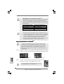
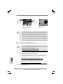
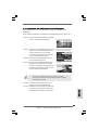
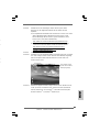
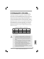
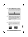
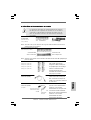
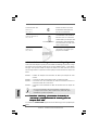
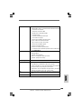
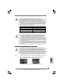
HD 8CH I/OHD 8CH I/O
HD 8CH I/OHD 8CH I/O
HD 8CH I/O
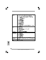
1 Parallel Port 8 Microphone (Pink)
2 RJ-45 Port 9 USB 2.0 Ports (USB01)
3 Side Speaker (Gray) 10 USB 2.0 Ports (USB23)
4 Rear Speaker (Black) 11 Serial Port: COM1
5 Central / Bass (Orange) 12 PS/2 Keyboard Port (Purple)
6 Line In (Light Blue) 13 PS/2 Mouse Port (Green)
*7 Front Speaker (Lime)
* If you use 2-channel speaker, please connect the speaker’s plug into “Front Speaker Jack”. See
the table below for connection details in accordance with the type of speaker you use.
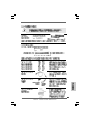
TABLE for Audio Output Connection
Audio Output Channels Front Speaker Rear Speaker Central / Bass Side Speaker
(No. 7) (No. 4) (No. 5) (No. 3)
2 V -- -- --
4VV----
6 VVV--
8 VVVV
* If you use 8-channel audio and enable Multi-Streaming function, “Side Speaker” will be disabled
. Therefore, only 6-channel audio function will work but not 8-channel audio. To enable Multi-
Streaming function, you need to connect a front panel audio cable to the front panel audio
header. After restarting your computer, you will find “Mixer” tool on your system. Please select
“Mixer ToolBox” , click “Enable playback multi-streaming”, and click “ok”. Choose
“2CH”, “4CH”, or “6CH”, and then you are allowed to select “Realtek HDA Primary output” to use
Rear Speaker, Central/Bass, and Front Speaker, or select “Realtek HDA Audio 2nd output” to
use front panel audio to share Side Speaker.

44
44
4
ASRock 775XFire-RAID Motherboard
EnglishEnglish
EnglishEnglish
English
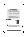
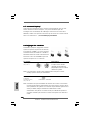
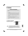
1. Introduction1. Introduction
1. Introduction1. Introduction
1. Introduction
Thank you for purchasing ASRock 775XFire-RAID motherboard, a reliable motherboard
produced under ASRock’s consistently stringent quality control. It delivers excellent
performance with robust design conforming to ASRock’s commitment to quality and
endurance.
This Quick Installation Guide contains introduction of the motherboard and step-by-
step installation guide. More detailed information of the motherboard can be found in
the user manual presented in the Support CD.
Because the motherboard specifications and the BIOS software might be
updated, the content of this manual will be subject to change without
notice. In case any modifications of this manual occur, the updated
version will be available on ASRock website without further notice. You
may find the latest VGA cards and CPU support lists on ASRock website
as well. ASRock website
http://www.asrock.com
1.1 Package Contents1.1 Package Contents
1.1 Package Contents1.1 Package Contents
1.1 Package Contents
ASRock 775XFire-RAID Motherboard
(ATX Form Factor: 12.0-in x 8.6-in, 30.5 cm x 21.8 cm)
ASRock 775XFire-RAID Quick Installation Guide
ASRock 775XFire-RAID Support CD
(including LGA 775 CPU Installation Live Demo)
One 80-conductor Ultra ATA 66/100 IDE Ribbon Cable
One Ribbon Cable for a 3.5-in Floppy Drive
One Serial ATA (SATA) Data Cable (Optional)
One Serial ATA (SATA) HDD Power Cable (Optional)
One HD 8CH I/O Panel Shield

55
55
5
ASRock 775XFire-RAID Motherboard
EnglishEnglish
EnglishEnglish
English
1.21.2
1.21.2
1.2
SpecificationsSpecifications
SpecificationsSpecifications
Specifications
Platform - ATX Form Factor: 12.0-in x 8.6-in, 30.5 cm x 21.8 cm
CPU - LGA 775 for Intel
®
Pentium
®
4 / Celeron
®
D, supporting Cedar
Mill processors (in 775-land LGA package)
- FSB 800/533 MHz
- Supports Hyper-Threading Technology (see CAUTION 1)
- Supports EM64T CPU
Chipset - Northbridge: Intel
®
925X chipset
- Southbridge: Intel
®
ICH6R
Memory - Dual Channel DDRII Memory Technology (see CAUTION 2)
- 4 x DDRII DIMM slots
- Support DDRII533
- Max. capacity: 4GB
Hybrid Booster - CPU Frequency Stepless Control (see CAUTION 3)
- ASRock U-COP (see CAUTION 4)
- Boot Failure Guard (B.F.G.)
Expansion Slot - Supports ATI
®
CrossFire
TM
- 3 x PCI slots
- 1 x PCI Express x 16 slot
- 1 x AGI Express slot (PCI Express x 4) (see CAUTION 5)
- 1 x PCI Express x 1 slot
Audio - Realtek ALC861 7.1 channel CODEC with High Definition
Audio
LAN - Realtek PCI LAN 8101L
- Speed: 10/100 Ethernet
- Supports Wake-On-LAN
Rear Panel I/O HD 8CH I/O
- 1 x PS/2 Mouse Port
- 1 x PS/2 Keyboard Port
- 1 x Serial Port: COM1
- 1 x Parallel Port (ECP/EPP Support)
- 4 x Ready-to-Use USB 2.0 Ports
- 1 x RJ-45 Port
- Audio Jack: Side Speaker/Rear Speaker/Central Bass/Line
in/Front Speaker/Microphone (see CAUTION 6)

66
66
6
ASRock 775XFire-RAID Motherboard
EnglishEnglish
EnglishEnglish
English
Connector - 4 x Serial ATA 1.5Gb/s connectors, support RAID (RAID 0,
RAID 1, and Intel Matrix Storage) and “Hot Plug” functions
- 1 x ATA100 IDE connector (supports 2 x IDE devices)
- 1 x Floppy connector
- 1 x IR header
- 1 x Game header
- CPU/Chassis FAN connector
- 20 pin ATX power connector
- 4 pin 12V power connector
- SLI/XFIRE power connector
- CD in header
- Front panel audio connector
- 2 x USB 2.0 headers (support 4 USB 2.0 ports)
(see CAUTION 7)
BIOS Feature - 4Mb AMI BIOS
- AMI Legal BIOS
- Supports “Plug and Play”
- ACPI 1.1 Compliance Wake Up Events
- Supports jumperfree
Support CD - Drivers, Utilities, AntiVirus Software
Hardware - CPU Temperature Sensing
Monitor - Chassis Temperature Sensing
- CPU Overheat Shutdown to Protect CPU Life
- CPU Fan Tachometer
- Chassis Fan Tachometer
- CPU Quiet Fan
- Voltage Monitoring: +12V, +5V, +3.3V, Vcore
OS - Microsoft
®
Windows
®
2000/XP/XP 64-bit compliant
Certifications - FCC, CE, WHQL

77
77
7
ASRock 775XFire-RAID Motherboard
EnglishEnglish
EnglishEnglish
English
CAUTION!
1. About the setting of “Hyper Threading Technology”, please check page 36
of “User Manual” in the Support CD.
2. This motherboard supports Dual Channel Memory Technology. Before you
implement Dual Channel Memory Technology, make sure to read the
installation guide of memory modules on page 12 for proper installation.
3. Although this motherboard offers stepless control, it is not recommended
to perform over-clocking. Frequencies other than the recommended CPU
bus frequencies may cause the instability of the system or damage the
CPU.
4. While CPU overheat is detected, the system will automatically shutdown.
Before you resume the system, please check if the CPU fan on the
motherboard functions properly and unplug the power cord, then plug it
back again. To improve heat dissipation, remember to spray thermal
grease between the CPU and the heatsink when you install the PC system.
5. If you install PCI Express VGA card to AGI Express slot (PCI Express x
4), PCIE2 slot (PCIE x 1) function will be disabled. For the information of
the compatible PCI Express VGA cards, please refer to the “Supported PCI
Express VGA Card List for AGI Express Slot (PCI Express x 4)” on page
8. For the proper installation of PCI Express VGA card, please refer to the
installation guide on page 14.
6. For microphone input, this motherboard supports both stereo and mono
modes. For audio output, this motherboard supports 2-channel, 4-channel,
6-channel, and 8-channel modes. Please check the table on page 3 for
proper connection.
7. Power Management for USB 2.0 works fine under Microsoft
®
Windows
®
XP
SP1 or SP2 / 2000 SP4.

88
88
8
ASRock 775XFire-RAID Motherboard
EnglishEnglish
EnglishEnglish
English
1.31.3
1.31.3
1.3
Supported PCI Express VGA Card List for AGISupported PCI Express VGA Card List for AGI
Supported PCI Express VGA Card List for AGISupported PCI Express VGA Card List for AGI
Supported PCI Express VGA Card List for AGI
Express Slot (PCI Express x 4)Express Slot (PCI Express x 4)
Express Slot (PCI Express x 4)Express Slot (PCI Express x 4)
Express Slot (PCI Express x 4)
(for Windows 2000/Windows XP)
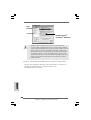
Graphics Chip Model Name Chipset Name
Vendor
NVIDIA
ATI
For the latest updates of the supported PCI Express VGA card list for AGI Express
slot (PCI Express x 4), please visit our website for details.
ASRock website:
http://www.asrock.com/support/index.htm
Note. It is not recommended to use Turbo cache PCI Express x 16 VGA cards.
ASUS Extreme N6200GE/TD GeForce 6200
ASUS Extreme N6200TC256/TD GeForce 6200
ASUS Extreme N6800/TD GeForce 6800
ASUS Extreme N6800GT GeForce 6800GT
ALBATRON PC6600GT GeForce 6600GT
GIGABYTE GV-NX66128D GeForce 6600
Inno3D GeFORCE 6600 LE GeForce 6600LE
LEADTEK PX6200 TC/TDH GeForce 6200TC
MSI PCX 5750-TD128E GeForce PCX5750
SPARKLE GeFORCE 6200TC GeForce 6200TC
ASUS Extreme AX600XT/HTVD RADEON X600XT
ASUS Extreme AX700PRO/TVD RADEON X700PRO
GECUBE Radeon X850XT 256M RADEON X850XT
MSI RX1300GPRO-TD256E RADEON X1300 PRO

99
99
9
ASRock 775XFire-RAID Motherboard
2.2.
2.2.
2.
InstallationInstallation
InstallationInstallation
Installation
Pre-installation PrecautionsPre-installation Precautions
Pre-installation PrecautionsPre-installation Precautions
Pre-installation Precautions
Take note of the following precautions before you install mother-
board components or change any motherboard settings.
1. Unplug the power cord from the wall socket before touching any
component. Failure to do so may cause severe damage to the
motherboard, peripherals, and/or components.
2. To avoid damaging the motherboard components due to static
electricity, NEVER place your motherboard directly on the carpet
or the like. Also remember to use a grounded wrist strap or touch
a safety grounded object before you handle components.
3. Hold components by the edges and do not touch the ICs.
4. Whenever you uninstall any component, place it on a grounded
antstatic pad or in the bag that comes with the component.
5. When placing screws into the screw holes to secure the
motherboard to the chassis, please do not over-tighten the
screws! Doing so may damage the motherboard.
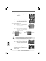
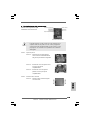
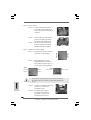
2.12.1
2.12.1
2.1
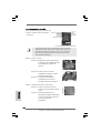
CPU InstallationCPU Installation
CPU InstallationCPU Installation
CPU Installation
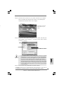
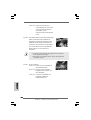
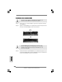
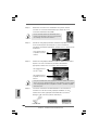
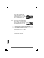
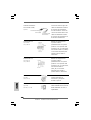
For the installation of Intel 775-LAND CPU,
please follow the steps below.
Before you insert the 775-LAND CPU into the socket, please check if
the CPU surface is unclean or if there is any bent pin on the socket.
Do not force to insert the CPU into the socket if above situation is
found. Otherwise, the CPU will be seriously damaged.
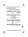
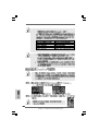
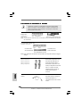
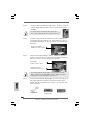
775-Pin Socket Overview
EnglishEnglish
EnglishEnglish
English

1010
1010
10
ASRock 775XFire-RAID Motherboard
EnglishEnglish
EnglishEnglish
English
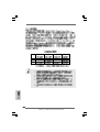
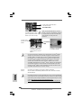
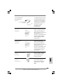
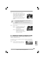
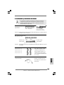
Step 1. Open the socket:
Step 1-1. Disengaging the lever by depressing
down and out on the hook to clear
retention tab.
Step 1-2. Rotate the load lever to fully open po-
sition at approximately 135 degrees.
Step 1-3. Rotate the load plate to fully open po-
sition at approximately 100 degrees.
Step 2. Insert the 775-LAND CPU:
Step 2-1. Hold the CPU by the edges where are
marked with black lines.
Step 2-2. Orient the CPU with IHS (Integrated
Heat Sink) up. Locate Pin1 and the two
orientation key notches.
For proper inserting, please ensure to match the two orientation key
notches of the CPU with the two alignment keys of the socket.
Step 2-3. Carefully place the CPU into the socket
by using a purely vertical motion.
Step 2-4. Verify that the CPU is within the socket
and properly mated to the orient keys.
Step 3. Remove PnP Cap (Pick and Place Cap):
Use your left hand index finger and thumb to
support the load plate edge, engage PnP cap
with right hand thumb and peel the cap from the
socket while pressing on center of PnP cap to
assist in removal.
black line
black line
775-Pin Socket
Pin1
alignment key
alignment key
Pin1
orientation
key notch
orientation
key notch
775-LAND CPU

1111
1111
11
ASRock 775XFire-RAID Motherboard
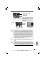
1. It is recommended to use the cap tab to handle and avoid kicking
off the PnP cap.
2. This cap must be placed if returning the motherboard for after
service.
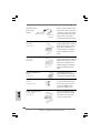
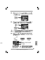
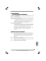
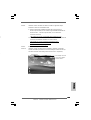
Step 4. Close the socket:
Step 4-1. Rotate the load plate onto the IHS.
Step 4-2. While pressing down lightly on load
plate, engage the load lever.
Step 4-3. Secure load lever with load plate tab
under retention tab of load lever.
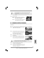
2.22.2
2.22.2
2.2
Installation of CPU Fan and HeatsinkInstallation of CPU Fan and Heatsink
Installation of CPU Fan and HeatsinkInstallation of CPU Fan and Heatsink
Installation of CPU Fan and Heatsink
For proper installation, please kindly refer to the instruction manuals of your CPU fan
and heatsink.
Below is an example to illustrate the installation of the heatsink for 775-LAND CPU.
Step 1. Apply thermal interface material onto center
of IHS on the socket surface.
Step 2. Place the heatsink onto the socket. Ensure
fan cables are oriented on side closest to the
CPU fan connector on the motherboard
(CPU_FAN1, see page 2, No. 6).
Step 3. Align fasteners with the motherboard
throughholes.
Step 4. Rotate the fastener clockwise, then press
down on fastener caps with thumb to install
and lock. Repeat with remaining fasteners.
If you press down the fasteners without rotating them clockwise,
the heatsink cannot be secured on the motherboard.
Step 5. Connect fan header with the CPU fan
connector on the motherboard.
Step 6. Secure excess cable with tie-wrap to ensure
cable does not interfere with fan operation or
contact other components.
EnglishEnglish
EnglishEnglish
English

1212
1212
12
ASRock 775XFire-RAID Motherboard
EnglishEnglish
EnglishEnglish
English
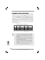
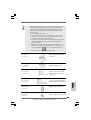
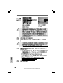
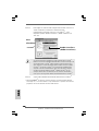
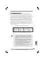
2.3 Installation of Memory Modules (DIMM)2.3 Installation of Memory Modules (DIMM)
2.3 Installation of Memory Modules (DIMM)2.3 Installation of Memory Modules (DIMM)
2.3 Installation of Memory Modules (DIMM)
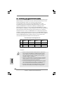
775XFire-RAID motherboard provides four 240-pin DDRII (Double Data Rate II)
DIMM slots, and supports Dual Channel Memory Technology. For dual channel
configuration, you always need to install identical (the same brand, speed,
size and chip-type) DDRII DIMM pair in the slots of the same color. In other words,
you have to install identical DDRII DIMM pair in Dual Channel A (DDRII_1 and
DDRII_3; Yellow slots; see p.2 No.7) or identical DDRII DIMM pair in Dual Chan-
nel B (DDRII_2 and DDRII_4; Orange slots; see p.2 No.8), so that Dual Channel
Memory Technology can be activated. This motherboard also allows you to
install four DDRII DIMMs for dual channel configuration, and please install iden-
tical DDRII DIMMs in all four slots. You may refer to the Dual Channel Memory
Configuration Table below.
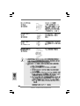
Dual Channel Memory Configurations
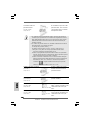
DDRII_1 DD RII_2 DDRII_3 DDRII_4
(Yellow Slot) (Orange Slot) (Yellow Slot) (Orange Slot)
(1) Populated - Populated -
(2) - Populated - Populated
(3)* Populated Populated Populated Populated
* For the configuration (3), please install identical DDRII DIMMs in all four slots.
1. If you want to install two memory modules, for optimal compatibility
and reliability, it is recommended to install them in the slots of the
same color. In other words, install them either in the set of yellow
slots (DDRII_1 and DDRII_3), or in the set of orange slots (DDRII_2
and DDRII_4).
2. If only one memory module or three memory modules are installed
in the DDRII DIMM slots on this motherboard, it is unable to activate
the Dual Channel Memory Technology.
3. If a pair of memory modules is NOT installed in the same Dual
Channel, for example, installing a pair of memory modules in DDRII_1
and DDRII_2, it is unable to activate the Dual Channel Memory
Technology .
4. It is not allowed to install a DDR memory module into DDRII slot;
otherwise, this motherboard and DIMM may be damaged.

1313
1313
13
ASRock 775XFire-RAID Motherboard
EnglishEnglish
EnglishEnglish
English
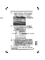
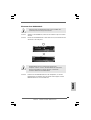
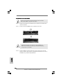
Installing a DIMMInstalling a DIMM
Installing a DIMMInstalling a DIMM
Installing a DIMM
Please make sure to disconnect power supply before adding or
removing DIMMs or the system components.
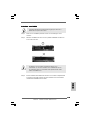
Step 1. Unlock a DIMM slot by pressing the retaining clips outward.
Step 2. Align a DIMM on the slot such that the notch on the DIMM matches the break
on the slot.
The DIMM only fits in one correct orientation. It will cause permanent
damage to the motherboard and the DIMM if you force the DIMM into the
slot at incorrect orientation.
Step 3. Firmly insert the DIMM into the slot until the retaining clips at both ends fully
snap back in place and the DIMM is properly seated.

1414
1414
14
ASRock 775XFire-RAID Motherboard
EnglishEnglish
EnglishEnglish
English
2.4 Expansion Slots (PCI, PCI Express, and AGI Express2.4 Expansion Slots (PCI, PCI Express, and AGI Express
2.4 Expansion Slots (PCI, PCI Express, and AGI Express2.4 Expansion Slots (PCI, PCI Express, and AGI Express
2.4 Expansion Slots (PCI, PCI Express, and AGI Express
Slots) Slots)
Slots) Slots)
Slots)
There are 3 PCI slots, 2 PCI Express slots, and 1 AGI Express slot (PCI Express x 4)
on this motherboard.
PCI slots: PCI slots are used to install expansion cards that have the 32-bit PCI
interface.
PCIE Slots: PCIE1 (PCIE x 16 slot) is used for PCI Express cards with x16 lane
width graphics cards.
PCIE2 (PCIE x 1 slot) is used for PCI Express cards, such as
Gigabit LAN card, SATA2 card, etc. Please check the jumper set
tings on page 15 for different functions.
AGI Express slot (PCI Express x 4):
AGI Express slot (PCI Express x 4) is used to install PCI Express expan-
sion cards. For the information of the compatible PCI Express VGA cards,
please refer to the “Supported PCI Express VGA Card List for AGI Ex-
press Slot (PCI Express x 4)” on page 8. Please check the jumper set-
tings on page 15 for different functions.
Installing an expansion cardInstalling an expansion card
Installing an expansion cardInstalling an expansion card
Installing an expansion card
Step 1. Before installing the expansion card, please make sure that the power
supply is switched off or the power cord is unplugged. Please read the
documentation of the expansion card and make necessary hardware
settings for the card before you start the installation.
Step 2. Remove the bracket facing the slot that you intend to use. Keep the screws
for later use.
Step 3. Align the card connector with the slot and press firmly until the card is
completely seated on the slot.
Step 4. Fasten the card to the chassis with screws.
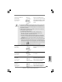
2.5 Dual Graphics Feature2.5 Dual Graphics Feature
2.5 Dual Graphics Feature2.5 Dual Graphics Feature
2.5 Dual Graphics Feature
This motherboard supports Dual Graphics Technology. When installing the add-on
VGA cards to this motherboard, you are allowed to choose two different ways to
decide the function of PCIE2 slot (PCIE x 1) and AGI Express slot. The default value
of this feature is to enable PCIE2 slot (PCIE x 1) and AGI Express slot (only PCI
Express x 1). You can also adjust the jumpers to disable PCIE2 slot (PCIE x 1). Then
only AGI Express slot (PCI Express x 4) will be enabled. In other words, you are able
to adjust the jumpers to enjoy the benefit of Dual Graphics feature. Please refer to the
table below for the correct jumper settings.

1515
1515
15
ASRock 775XFire-RAID Motherboard
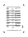
Function Jumper Settings
PCIE x 1_EN4
PCIE x 1_EN3
PCIE x 1_EN2
PCIE x 1_EN1
PCIE x 1_EN4
PCIE x 1_EN3
PCIE x 1_EN2
PCIE x 1_EN1
EnglishEnglish
EnglishEnglish
English
Enable
PCIE2 /
AGI Express
(only PCIE x 1)
(Default)
Enable
AGI Express
(PCIE x 4)
(Disable PCIE2)
PCIE x 1_EN5
PCIE x 1_EN5
2.6 CrossFire2.6 CrossFire
2.6 CrossFire2.6 CrossFire
2.6 CrossFire
TMTM
TMTM
TM
Operation Guide Operation Guide
Operation Guide Operation Guide
Operation Guide
This motherboard supports CrossFire
TM
feature. CrossFire
TM
technology offers the
most advantageous means available of combining multiple high performance Graphics
Processing Units (GPU) in a single PC. Combining a range of different operating
modes with intelligent software design and an innovative interconnect mechanism,
CrossFire
TM
enables the highest possible level of performance and image quality in
any 3D application. Currently CrossFire
TM
feature is only supported with Windows
XP with Service Pack 2; it may be supported with other OS in the future.

1616
1616
16
ASRock 775XFire-RAID Motherboard
EnglishEnglish
EnglishEnglish
English
1. If a customer incorrectly configures their system they will not see the
performance benefits of CrossFire
TM
. All three CrossFire
TM
components, a
CrossFire
TM
Ready graphics card, a CrossFire
TM
Ready motherboard and
a CrossFire
TM
Edition co-processor graphics card, must be installed
correctly to benefit from the CrossFire
TM
multi-GPU platform.
2. If you pair a 12-pipe CrossFire
TM
Edition card with a 16-pipe card, both
cards will operate as 12-pipe cards while in CrossFire
TM
mode.
Enjoy the benefit of CrossFireEnjoy the benefit of CrossFire
Enjoy the benefit of CrossFireEnjoy the benefit of CrossFire
Enjoy the benefit of CrossFire
TMTM
TMTM
TM
Step 1. Adjust the jumpers on this motherboard to enable AGI Express slot (PCI
Express x 4). Please refer to the pictures below for proper jumper setting.
Currently, ATI has released Radeon X850XT, X1800XT, X1300, and X1600
CrossFire
TM
cards, which require different methods to enable CrossFire
TM
feature. In the below procedures, we use Radeon X850XT as the example
graphics card. For other CrossFire
TM
cards that ATI has released or will
release in the future, please refer to ATI graphics card manuals for detailed
installation guide.
It is recommended to use 500-Watt power supply or greater
to perform the benefit of CrossFire
TM
feature.
Step 2. Connect to the system power supply. Please connect a hard
disk power connector to SLI/XFIRE Power connector.
PCIEx1_EN1-4: Short Pin1, Pin2
What graphics cards work with CrossFire
TM
?
A complete CrossFire
TM
system requires a CrossFire
TM
Ready motherboard,
a CrossFire
TM
Edition graphics card and a compatible standard Radeon
(CrossFire
TM
Ready) graphics card from the same series, or two CrossFire
TM
Ready cards if they are software enabled. This applies to cards from ATI or
any of its partners.
Cards For AGI Express Slot Cards For PCI Express Slot
Radeon X1800 Series Radeon X1800 CrossFire
TM
Edition
Radeon X1600 Series Radeon X1600 Series
Radeon X1300 Series Radeon X1300 Series
Radeon X850 Series Radeon X850 CrossFire
TM
Edition
PCIEx1_EN5: Short Pin1, Pin2

1717
1717
17
ASRock 775XFire-RAID Motherboard
EnglishEnglish
EnglishEnglish
English
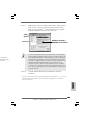
Step 3. Install the standard Radeon (CrossFire
TM
Ready) graphics card to AGI Ex-
press slot (PCI Express x 4). For the proper installation procedures, please
refer to section “Expansion Slots”.
Step 4. Install the Radeon CrossFire
TM
Edition graphics card to PCI Express x 16
slot. For the proper installation procedures, please refer to section “Expan-
sion Slots”.
DVI-DMS cable DMS connector
DVI connector
You are allowed to install two CrossFire
TM
Edition graphics cards to both slots,
or you may use one CrossFire
TM
Edition graphics cards and a compatible
standard Radeon (CrossFire
TM
Ready) graphics card from the same series.
Connect the DVI-DMS
cable to DVI connector of
the compatible standard
Radeon (CrossFire
TM
Ready) graphics card.
Standard Radeon
(CrossFire
TM
Ready)
graphics card
Standard Radeon
(CrossFire
TM
Ready)
graphics card
Radeon CrossFire
TM
Edition graphics card
DVI connector
Standard Radeon (CrossFire
TM
Ready)
graphics card
There are two DVI connectors on the
standard Radeon (CrossFire
TM
Ready)
graphics card. Please connect the DVI-DMS
cable to the correct DVI connector; otherwise
, the graphics card will not work.
ss Slot
re
TM
Edition
e
TM
Edition
Step 5. Correctly connect the DVI-DMS cable to the monitor connector and two
graphics cards that you install. (If you install two standard Radeon
(CrossFire
TM
Ready) graphics cards to this motherboard, please skip this
step.)
1, Pin2

1818
1818
18
ASRock 775XFire-RAID Motherboard
EnglishEnglish
EnglishEnglish
English
Step 6. Power on your computer and boot into OS.
Step 7. Remove the ATI driver if you have any VGA driver installed in your system.
If you install two CrossFire
TM
Edition graphics cards to this motherboard, please
connect one end of DVI-DMS cable to the monitor, another end to DMS of one
of the CrossFire
TM
Edition graphics cards to PCIE1 slot (PCI Express x 16), and
the other end to DVI of another CrossFire
TM
Edition graphics card to AGI
Express slot (PCI Express x 4). If you install one CrossFire
TM
Edition graphics
card and one compatible standard Radeon (CrossFire
TM
Ready) graphics card
to this motherboard, please connect one end of DVI-DMS cable to the monitor,
another end to DMS of the CrossFire
TM
Edition graphics card, and the other end
to DVI of the compatible standard Radeon (CrossFire
TM
Ready) graphics card.
Connect the DVI-DMS
cable to the monitor
connector.
Connect the DVI-DMS
cable to DMS connector
of the CrossFire
TM
Edition
graphics card.
The Catalyst Uninstaller is an optional download. We recommend using this
utility to uninstall any previously installed Catalyst drivers prior to installation.
Please visit this website for the driver:
http://support.ati.com/ics/support/DLRedirect.asp?
fileIDExt=050553d40196ef109fff37cbb40aaf28&accountID=737&deptID=894
Step 8. Install the required drivers to your system. Please visit the websites below
for installing the drivers that ATI recommends:
A. ATI recommends Windows XP Service Pack 2 or higher to be installed
(If you have Windows XP Service Pack 2 or higher installed in your
system, there is no need to download it again):
http://www.microsoft.com/windowsxp/sp2/default.mspx
B. You must have Microsoft .NET Framework installed prior to
downloading and installing the CATALYST Control Center:
http://www.microsoft.com/downloads/details.aspx?
FamilyId=262D25E3-F589-4842-8157-034D1E7CF3A3&displaylang=en
DMS
connector
Radeon
CrossFire
TM
Edition graphics
card
Step 9. Restart your computer.

1919
1919
19
ASRock 775XFire-RAID Motherboard
EnglishEnglish
EnglishEnglish
English
t
t
o
If you install one Radeon CrossFire
TM
Edition graphics card and one compatible
standard Radeon (CrossFire
TM
Ready) graphics card to this motherboard but
not two Radeon CrossFire
TM
Edition graphics cards, please as well follow the
above steps. However, although you have selected the option “Enable
CrossFire
TM
”, the CrossFire
TM
function can not work actually. Your computer
will automatically reboot. After restarting your computer, please confirm whether
the option “Enable CrossFire
TM
” in “ATI Catalyst Control Center” is selected or
not; if not, please select it again, and then you are able to enjoy the benefit of
CrossFire
TM
feature.
Step 12. You can freely enjoy the benefit of CrossFire
TM
feature.
Step 11. Double-click “ATI Catalyst Control Center”. Click “View”, and select “Ad-
vanced View”. Click “CrossFire
TM
”, and then set the option “Enable
CrossFire
TM
” to “Yes”.
Step 10. Install the VGA card drivers to your system, and restart your computer.
Then you will find “ATI Catalyst Control Center” on your desktop (ATI
Catalyst driver should be version 5.10 or higher).
You will find “ATI Catalyst
Control Center” on your
desktop.
View
CrossFire
TM
Enable CrossFire
TM
* CrossFire
TM
appearing here is a registered trademark of ATI Technologies Inc., and is used only
for identification or explanation and to the owners’ benefit, without intent to infringe.

2020
2020
20
ASRock 775XFire-RAID Motherboard
EnglishEnglish
EnglishEnglish
English
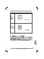
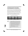
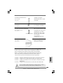
2-pin jumper
Short Open
2.7 Surround Display Feature2.7 Surround Display Feature
2.7 Surround Display Feature2.7 Surround Display Feature
2.7 Surround Display Feature
This motherboard supports Surround Display upgrade. With the external add-on
PCI Express VGA card, you can easily enjoy the benefits of Surround Display
feature. For the detailed instruction, please refer to the document at the following
path in the Support CD:
..\ Surround Display Information
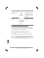
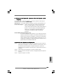
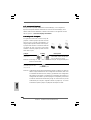
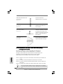
2.8 Jumpers Setup2.8 Jumpers Setup
2.8 Jumpers Setup2.8 Jumpers Setup
2.8 Jumpers Setup
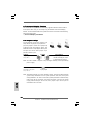
The illustration shows how jumpers are
setup. When the jumper cap is placed on
pins, the jumper is “Short”. If no jumper cap
is placed on pins, the jumper is “Open”. The
illustration shows a 3-pin jumper whose pin1
and pin2 are “Short” when jumper cap is
placed on these 2 pins.
Jumper Setting Description
PS2_USB_PWR1 Short pin2, pin3 to enable
(see p.2 No. 1) +5VSB (standby) for PS/2
or USB wake up events.
Note: To select +5VSB, it requires 2 Amp and higher standby current provided by
power supply.
Clear CMOS
(CLRCMOS1, 2-pin jumper)
(see p.2 No. 10)
Note: CLRCMOS1 allows you to clear the data in CMOS. The data in CMOS includes
system setup information such as system password, date, time, and system
setup parameters. To clear and reset the system parameters to default setup,
please turn off the computer and unplug the power cord from the power
supply. After waiting for 15 seconds, use a jumper cap to short 2 pins on
CLRCMOS1 for 5 seconds.
La pagina si sta caricando...
La pagina si sta caricando...
La pagina si sta caricando...
La pagina si sta caricando...
La pagina si sta caricando...
La pagina si sta caricando...
La pagina si sta caricando...
La pagina si sta caricando...
La pagina si sta caricando...
La pagina si sta caricando...
La pagina si sta caricando...
La pagina si sta caricando...
La pagina si sta caricando...
La pagina si sta caricando...
La pagina si sta caricando...
La pagina si sta caricando...
La pagina si sta caricando...
La pagina si sta caricando...
La pagina si sta caricando...
La pagina si sta caricando...
La pagina si sta caricando...
La pagina si sta caricando...
La pagina si sta caricando...
La pagina si sta caricando...
La pagina si sta caricando...
La pagina si sta caricando...
La pagina si sta caricando...
La pagina si sta caricando...
La pagina si sta caricando...
La pagina si sta caricando...
La pagina si sta caricando...
La pagina si sta caricando...
La pagina si sta caricando...
La pagina si sta caricando...
La pagina si sta caricando...
La pagina si sta caricando...
La pagina si sta caricando...
La pagina si sta caricando...
La pagina si sta caricando...
La pagina si sta caricando...
La pagina si sta caricando...
La pagina si sta caricando...
La pagina si sta caricando...
La pagina si sta caricando...
La pagina si sta caricando...
La pagina si sta caricando...
La pagina si sta caricando...
La pagina si sta caricando...
La pagina si sta caricando...
La pagina si sta caricando...
La pagina si sta caricando...
La pagina si sta caricando...
La pagina si sta caricando...
La pagina si sta caricando...
La pagina si sta caricando...
La pagina si sta caricando...
La pagina si sta caricando...
La pagina si sta caricando...
La pagina si sta caricando...
La pagina si sta caricando...
La pagina si sta caricando...
La pagina si sta caricando...
La pagina si sta caricando...
La pagina si sta caricando...
La pagina si sta caricando...
La pagina si sta caricando...
La pagina si sta caricando...
La pagina si sta caricando...
La pagina si sta caricando...
La pagina si sta caricando...
La pagina si sta caricando...
La pagina si sta caricando...
La pagina si sta caricando...
La pagina si sta caricando...
La pagina si sta caricando...
La pagina si sta caricando...
La pagina si sta caricando...
La pagina si sta caricando...
La pagina si sta caricando...
La pagina si sta caricando...
La pagina si sta caricando...
La pagina si sta caricando...
La pagina si sta caricando...
La pagina si sta caricando...
La pagina si sta caricando...
La pagina si sta caricando...
La pagina si sta caricando...
La pagina si sta caricando...
La pagina si sta caricando...
La pagina si sta caricando...
La pagina si sta caricando...
La pagina si sta caricando...
La pagina si sta caricando...
La pagina si sta caricando...
La pagina si sta caricando...
La pagina si sta caricando...
La pagina si sta caricando...
La pagina si sta caricando...
La pagina si sta caricando...
La pagina si sta caricando...
La pagina si sta caricando...
La pagina si sta caricando...
La pagina si sta caricando...
La pagina si sta caricando...
La pagina si sta caricando...
La pagina si sta caricando...
La pagina si sta caricando...
La pagina si sta caricando...
La pagina si sta caricando...
La pagina si sta caricando...
La pagina si sta caricando...
La pagina si sta caricando...
La pagina si sta caricando...
La pagina si sta caricando...
La pagina si sta caricando...
La pagina si sta caricando...
La pagina si sta caricando...
La pagina si sta caricando...
La pagina si sta caricando...
La pagina si sta caricando...
La pagina si sta caricando...
La pagina si sta caricando...
La pagina si sta caricando...
La pagina si sta caricando...
La pagina si sta caricando...
La pagina si sta caricando...
La pagina si sta caricando...
La pagina si sta caricando...
La pagina si sta caricando...
La pagina si sta caricando...
La pagina si sta caricando...
La pagina si sta caricando...
La pagina si sta caricando...
La pagina si sta caricando...
La pagina si sta caricando...
La pagina si sta caricando...
La pagina si sta caricando...
La pagina si sta caricando...
La pagina si sta caricando...
La pagina si sta caricando...
La pagina si sta caricando...
La pagina si sta caricando...
La pagina si sta caricando...
-
 1
1
-
 2
2
-
 3
3
-
 4
4
-
 5
5
-
 6
6
-
 7
7
-
 8
8
-
 9
9
-
 10
10
-
 11
11
-
 12
12
-
 13
13
-
 14
14
-
 15
15
-
 16
16
-
 17
17
-
 18
18
-
 19
19
-
 20
20
-
 21
21
-
 22
22
-
 23
23
-
 24
24
-
 25
25
-
 26
26
-
 27
27
-
 28
28
-
 29
29
-
 30
30
-
 31
31
-
 32
32
-
 33
33
-
 34
34
-
 35
35
-
 36
36
-
 37
37
-
 38
38
-
 39
39
-
 40
40
-
 41
41
-
 42
42
-
 43
43
-
 44
44
-
 45
45
-
 46
46
-
 47
47
-
 48
48
-
 49
49
-
 50
50
-
 51
51
-
 52
52
-
 53
53
-
 54
54
-
 55
55
-
 56
56
-
 57
57
-
 58
58
-
 59
59
-
 60
60
-
 61
61
-
 62
62
-
 63
63
-
 64
64
-
 65
65
-
 66
66
-
 67
67
-
 68
68
-
 69
69
-
 70
70
-
 71
71
-
 72
72
-
 73
73
-
 74
74
-
 75
75
-
 76
76
-
 77
77
-
 78
78
-
 79
79
-
 80
80
-
 81
81
-
 82
82
-
 83
83
-
 84
84
-
 85
85
-
 86
86
-
 87
87
-
 88
88
-
 89
89
-
 90
90
-
 91
91
-
 92
92
-
 93
93
-
 94
94
-
 95
95
-
 96
96
-
 97
97
-
 98
98
-
 99
99
-
 100
100
-
 101
101
-
 102
102
-
 103
103
-
 104
104
-
 105
105
-
 106
106
-
 107
107
-
 108
108
-
 109
109
-
 110
110
-
 111
111
-
 112
112
-
 113
113
-
 114
114
-
 115
115
-
 116
116
-
 117
117
-
 118
118
-
 119
119
-
 120
120
-
 121
121
-
 122
122
-
 123
123
-
 124
124
-
 125
125
-
 126
126
-
 127
127
-
 128
128
-
 129
129
-
 130
130
-
 131
131
-
 132
132
-
 133
133
-
 134
134
-
 135
135
-
 136
136
-
 137
137
-
 138
138
-
 139
139
-
 140
140
-
 141
141
-
 142
142
-
 143
143
-
 144
144
-
 145
145
-
 146
146
-
 147
147
-
 148
148
-
 149
149
-
 150
150
-
 151
151
-
 152
152
-
 153
153
-
 154
154
-
 155
155
-
 156
156
-
 157
157
-
 158
158
-
 159
159
-
 160
160
-
 161
161
-
 162
162
-
 163
163


ASROCK 775XFire-RAID Manuale del proprietario
- Categoria
- Schede madri
- Tipo
- Manuale del proprietario
in altre lingue
Documenti correlati
-
ASROCK 775XFIRE-ESATA2 - 02-2006 Manuale del proprietario
-
ASROCK 775XFIRE-ESATA2 PLUS Manuale del proprietario
-
ASROCK P4DUAL-915GL Manuale del proprietario
-
ASROCK CONROEXFIRE-ESATA2-1335 Manuale del proprietario
-
ASROCK CONROE865GV Manuale del proprietario
-
ASROCK 4Core1333-eSATA2 Manuale del proprietario
-
ASROCK 775i915P-SATA2 Manuale del proprietario
-
ASROCK 4CORE1600TWINS-P35D Manuale del proprietario
-
ASROCK 4Core1600Twins-P35 Manuale del proprietario
-
ASROCK 4CORE1600P35-WIFI PLUS Manuale del proprietario
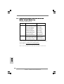
Altri documenti
-
PEAK Radeon HD4870 512MB 256bit PCI-E2.0 Manuale utente
-
Dell XPS 730 H2C Guida Rapida
-
Samsung HD103UJ Guida d'installazione
-
Samsung SP0612N Manuale utente
-
Hama 00049278 Manuale del proprietario
-
Gigabyte GV-RX30128D Manuale del proprietario
-
 Conitech All-in-One Scheda dati
-
 Conitech All-in-One Manuale del proprietario
-
 Sapphire Technology 11265-05-20G Manuale utente
-
 Sapphire Technology 11265-05-20G Manuale utente


