3com 3CR16708-91 Manuale utente
- Categoria
- Switch di rete
- Tipo
- Manuale utente
Questo manuale è adatto anche per

http://www.3com.com/
Part No. DUA1670-8AAA01
Published March 2005
OfficeConnect
®
Managed
Switch 9 and Switch 9 FX
Getting Started Guide
3CR16708-91
3CR16709-91

3Com Corporation
350 Campus Drive
Marlborough, MA
USA 01752-3064
Copyright © 2005, 3Com Corporation. All rights reserved. No part of this documentation may be reproduced
in any form or by any means or used to make any derivative work (such as translation, transformation, or
adaptation) without written permission from 3Com Corporation.
3Com Corporation reserves the right to revise this documentation and to make changes in content from time
to time without obligation on the part of 3Com Corporation to provide notification of such revision or change.
3Com Corporation provides this documentation without warranty, term, or condition of any kind, either
implied or expressed, including, but not limited to, the implied warranties, terms or conditions of
merchantability, satisfactory quality, and fitness for a particular purpose. 3Com may make improvements or
changes in the product(s) and/or the program(s) described in this documentation at any time.
If there is any software on removable media described in this documentation, it is furnished under a license
agreement included with the product as a separate document, in the hard copy documentation, or on the
removable media in a directory file named LICENSE.TXT or !LICENSE.TXT. If you are unable to locate a copy,
please contact 3Com and a copy will be provided to you.
UNITED STATES GOVERNMENT LEGEND
If you are a United States government agency, then this documentation and the software described herein are
provided to you subject to the following:
All technical data and computer software are commercial in nature and developed solely at private expense.
Software is delivered as “Commercial Computer Software” as defined in DFARS 252.227-7014 (June 1995) or
as a “commercial item” as defined in FAR 2.101(a) and as such is provided with only such rights as are
provided in 3Com’s standard commercial license for the Software. Technical data is provided with limited rights
only as provided in DFAR 252.227-7015 (Nov 1995) or FAR 52.227-14 (June 1987), whichever is applicable.
You agree not to remove or deface any portion of any legend provided on any licensed program or
documentation contained in, or delivered to you in conjunction with, this User Guide.
Unless otherwise indicated, 3Com registered trademarks are registered in the United States and may or may not
be registered in other countries.
3Com, OfficeConnect, and the 3Com logo are registered trademarks of 3Com Corporation.
IEEE and 802 are registered trademarks of the Institute of Electrical and Electronics Engineers, Inc.
Intel and Pentium are registered trademarks of Intel Corporation. Microsoft, MS-DOS, Windows, and Windows
NT are registered trademarks of Microsoft Corporation. Novell and NetWare are registered trademarks of
Novell, Inc. UNIX is a registered trademark in the United States and other countries, licensed exclusively
through X/Open Company, Ltd.
Netscape Navigator is a registered trademark of Netscape Communications.
JavaScript is a trademark of Sun Microsystems.
All other company and product names may be trademarks of the respective companies with which they are
associated.
ENVIRONMENTAL STATEMENT
It is the policy of 3Com Corporation to be environmentally-friendly in all operations. To uphold our policy, we
are committed to:
Establishing environmental performance standards that comply with national legislation and regulations.
Conserving energy, materials and natural resources in all operations.
Reducing the waste generated by all operations. Ensuring that all waste conforms to recognized environmental
standards. Maximizing the recyclable and reusable content of all products.
Ensuring that all products can be recycled, reused and disposed of safely.
Ensuring that all products are labelled according to recognized environmental standards.
Improving our environmental record on a continual basis.
End of Life Statement
3Com processes allow for the recovery, reclamation and safe disposal of all end-of-life electronic components.
Regulated Materials Statement
3Com products do not contain any hazardous or ozone-depleting material.
Environmental Statement about the Documentation
The documentation for this product is printed on paper that comes from sustainable, managed forests; it is
fully biodegradable and recyclable, and is completely chlorine-free. The varnish is environmentally-friendly, and
the inks are vegetable-based with a low heavy-metal content.
ENCRYPTION
This product contains encryption and may require U.S. and/or local government authorization prior to export
or import to another country.

CONTENTS
ABOUT THIS GUIDE
Before You Start 7
About Your CD-ROM 7
Conventions 8
Related Documentation 9
Accessing Online Documentation 9
Documentation Comments 10
1 INTRODUCING THE OFFICECONNECT MANAGED
S
WITCH 9 AND SWITCH 9FX
About the Switch 12
Summary of Hardware Features 12
Switch — Front View Detail 13
LEDs 14
Switch — Rear View Detail 16
10BASE-T/ 100BASE-TX Ports 17
10BASE-T/ 100BASE-TX/
1000BASE-T Port 17
SFP Port 17
100BASE-FX Port 18
Console Port 18
Power Socket 18
Default Settings 19
2 INSTALLING THE SWITCH
Package Contents 22
Choosing a Suitable Site 22
Placing Units On Top of Each Other 23
Using a Stacking Clip 23
Wall-mounting 24

Mounting Instructions for Cement Walls 24
Mounting Instructions for Wood Walls 25
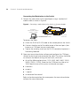
The Power-up Sequence 25
Powering-up the Switch 25
Checking for Correct Operation of LEDs 26
Using Power over Ethernet 26
Choosing the Correct RJ-45 Cables 28
SFP Operation 29
Approved SFP Transceivers 29
Inserting an SFP Transceiver 29
Removing an SFP Transceiver 31
3 SETTING UP FOR MANAGEMENT
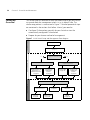
Setting Up Overview 34
IP Configuration 35
Preparing for Management 36
Manually Configuring IP Information 37
Connecting to the Console Port 37
Viewing Automatically Configured IP Information 40
Using 3Com Network Supervisor 40
Connecting to the Console Port 41
Methods of Managing a Switch 43
Command Line Interface Management 43
Web Interface Management 44
SNMP Management 44
Setting Up Command Line Interface Management 45
CLI Management via the Console Port 45
CLI Management over the Network 45
Setting Up Web Interface Management 46
Pre-requisites 46
Web Management Over the Network 47
Setting Up SNMP Management 47
Pre-requisites 48
Default Users and Passwords 48
Changing Default Passwords 48

4 PROBLEM SOLVING
Solving Problems Indicated by LEDs 52
Solving Hardware Problems 53
Solving Communication Problems 54
Solving Software Upgrade Problems 55
Recovering from a Lost Password 55
A SAFETY INFORMATION
Power Cord Set — Japan 58
Important Safety Information 58
L’information de Sécurité Importante 60
Wichtige Sicherheitsinformationen 62
Información de seguridad importante 64
Importanti Informazioni di Sicurezza 66
B PIN-OUTS
RJ-45 to RS-232 Adapter Cable 69
RJ-45 Pin Assignments 70
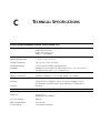
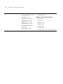
C TECHNICAL SPECIFICATIONS
OfficeConnect Managed Switch 9 and Switch 9 FX 71
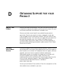
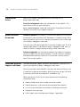
D OBTAINING SUPPORT FOR YOUR PRODUCT
Register Your Product 73
Purchase Value-Added Services 73
Troubleshoot Online 74
Access Software Downloads 74
Telephone Technical Support and Repair 74
Contact Us 75
INDEX
REGULATORY NOTICES


ABOUT THIS GUIDE
This guide provides all the information you need to install and use the
following switches in their default state.
■ OfficeConnect Managed Switch 9 (3CR16708-91)
■ OfficeConnect Managed Switch 9 FX (3CR16709-91)
All procedures described in this guide apply to both models except where
stated. Where a procedure or description applies to both the Switch 9
and the Switch 9 FX, the term Switch is used.
The guide is intended for use by network administrators who are
responsible for installing and setting up network equipment;
consequently, it assumes a basic working knowledge of LANs (Local Area
Networks).
Before You Start This section contains information about the CD-ROM that accompanies
your Switch.
About Your CD-ROM The CD-ROM also contains the following:
■ Online documentation for the Switch — refer to Related
Documentation on page 9 for details.
■ 3Com Network Supervisor — a powerful and easy-to-use network
management platform.
■ A number of other useful applications.
Most user guides and release notes are available in Adobe Acrobat
Reader Portable Document Format (PDF) or HTML on the 3Com
World Wide Web site:
http://www.3com.com/

8 ABOUT THIS GUIDE
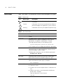
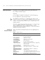
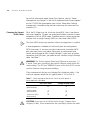
Conventions Table 1 and Table 2 list conventions that are used throughout this guide.
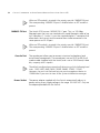
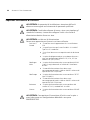
Table 1 Notice Icons
Icon Notice Type Description
Information note Information that describes important features or
instructions
Caution Information that alerts you to potential loss of data or
potential damage to an application, system, or device
Warning Information that alerts you to potential personal injury
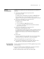
Table 2 Text Conventions
Convention Description
Screen displays This typeface represents information as it appears on the
screen.
<syntax> The word “syntax” means that you must evaluate the syntax
provided and then supply the appropriate values for the
placeholders that appear in angle brackets. Example:
To change your password, use the following syntax:
system management password <password>
In this example, you must supply a password for <password>.
Commands The word “command” means that you must enter the
command exactly as shown and then press Return or Enter.
Commands appear in bold. Example:
To display port information, enter the following command:
bridge port detail
The words “enter”
and “type”
When you see the word “enter” in this guide, you must type
something, and then press Return or Enter. Do not press
Return or Enter when an instruction simply says “type.”
Keyboard key names If you must press two or more keys simultaneously, the key
names are linked with a plus sign (+). Example:
Press Ctrl+Alt+Del
Words in italics Italics are used to:
■ Emphasize a point.
■ Denote a new term at the place where it is defined in the
text.
■ Identify menu names, menu commands, and software
button names. Examples:
From the Help menu, select Contents.
Click OK.

Related Documentation 9
Related
Documentation
In addition to this guide, each Switch documentation set includes the
following:
■ OfficeConnect Managed Switch 9 and Switch 9 FX
Implementation Guide
This guide contains information on the features supported by your
Switch and how they can be used to optimize your network. It is
supplied in PDF format on the CD-ROM that accompanies the Switch.
■ OfficeConnect Managed Switch 9 and Switch 9 FX
Management Quick Reference Guide
This guide contains:
■ a list of the features supported by the Switch.
■ a summary of the Web interface and command line interface
commands for the Switch.
■ OfficeConnect Managed Switch 9 and Switch 9 FX
Management Interface Reference Guide
This guide provides detailed information about the Web interface and
command line interface that enable you to manage the Switch. It is
supplied in HTML format on the CD-ROM that accompanies the
Switch.
■ Release Notes
These notes provide information about the current software release,
including new features, modifications, and known problems.
There are other publications you may find useful, such as:
■ Documentation accompanying 3Com Network Supervisor. This is
supplied on the CD-ROM that accompanies the Switch.
Accessing Online
Documentation
To access the documentation on the CD-ROM supplied with your Switch,
do the following:
1 Insert the CD-ROM into your CD-ROM drive. If your PC has auto-run
enabled, a splash screen will be displayed automatically.
2 Select the Documentation section from the contents page.

10 ABOUT THIS GUIDE
If the online documentation is to be accessed from a local drive or server,
you will need to access the CD-ROM contents via the root directory and
copy the files from the CD-ROM to a suitable directory.
■ The HTML Reference Guide is stored in the Docs/reference
directory on the CD-ROM. The documentation is accessed using the
contents.htm file.
■ The PDF Implementation Guide is stored in the
Docs/implementation directory of the CD-ROM.
3Com recommends that you copy the
Docs/reference directory as a
whole to maintain the structure of the files.
Documentation
Comments
Your suggestions are very important to us. They will help make our
documentation more useful to you. Please e-mail comments about this
document to 3Com at:
pddtechpubs_comments@3com.com
Please include the following information when commenting:
■ Document title
■ Document part number (on the title page)
■ Page number (if appropriate)
Example:
■ OfficeConnect Managed Switch 9 and Switch 9 FX
Getting Started Guide
■ Part Number DUA1670-8AAA01
■ Page 21
Please note that we can only respond to comments and questions about
3Com product documentation at this e-mail address. Questions related to
technical support or sales should be directed in the first instance to your
network supplier.

1
INTRODUCING THE
OFFICECONNECT MANAGED
SWITCH 9 AND SWITCH 9FX
This chapter contains introductory information about the Switch 9 and
Switch 9 FX and how they can be used in your network. It covers
summaries of hardware and software features and also the following
topics:
■ About the Switch
■ Switch — Front View Detail
■ Switch — Rear View Detail
■ Default Settings

12 CHAPTER 1: INTRODUCING THE OFFICECONNECT MANAGED SWITCH 9 AND SWITCH 9FX
About the Switch The Switch is a 10/100 Mbps Ethernet Switch, which consists of:
■ 8 10BASE-T/100BASE-TX ports
and either:
■ One 10BASE-T/100BASE-TX/1000BASE-T (10/100/1000) port or
■ One 100BASE-FX LC port and one SFP port
The 100BASE-FX and SFP port is a combination port. When an SFP
module is inserted it has priority over the 100BASE-FX port of the same
number. The corresponding 100BASE-FX port is disabled when an SFP
module is present.
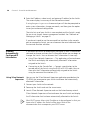
The Switch supports Power over Ethernet on ports 1, 2, 5 and 6. If you
plug in a compatible (IEEE 802.3af compliant) device, it will be
automatically detected and power supplied to it. Power over Ethernet is
enabled on these ports by default.
Summary of
Hardware Features
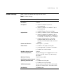
Table 3 summarizes the hardware features that are supported by the
Switch.
Table 3 Hardware features
Feature Switch
MAC Addresses ■ Up to 8000 supported
■ Up to 64 static entries
Auto-negotiation Supported on all ports
Auto MDI/MDI-X Supported on all RJ-45 ports
Forwarding Modes Store and Forward
Duplex Modes Half and full duplex on all ports
Traffic Prioritization Supported (using the IEEE Std 802.ID, 1998 Edition):
4 queues per port
Power over Ethernet Supported on ports 1, 2, 5 and 6
Ethernet/Fast Ethernet
Ports
Auto-negotiating 10BASE-T / 100BASE-TX ports
Ethernet/Fast Ethernet/
Gigabit Ethernet Ports
1 auto-negotiating 10BASE-T / 100BASE-TX /
1000BASE-T port
SFP Port 1 auto-negotiating SFP port on Switch 9 FX
Fiber-Optic Port 1 auto-negotiating 100BASE-FX port on Switch 9 FX
Mounting Wall mounting or stand-alone mounting

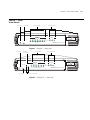
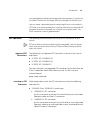
Switch — Front View Detail 13
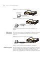
Switch — Front
View Detail
Figure 1 Switch 9 — front view
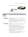
Figure 2 Switch 9 FX — front view
3CR16708-91
678
Blue = 1000M, Green = 100M, Yellow = 10M, Flash = Activity
Duplex : On = Full
OfficeConnect Managed Switch 9
GbE
Alert
Duplex
Link/Activity
On = Delivering Power
PoE Status
6
Port Status LEDS PoE Status LEDSPower LEDAlert LED
3CR16709-91
678
Green = 100M, Yellow = 10M, Flash = Activity
Duplex : On = Full
OfficeConnect Managed Switch 9 FX
Alert
Duplex
Link/Activity
On = Delivering Power
PoE Status
6
SFP FX
Green = Link
Flash = Activity
Module Status
Power LED
Alert LED
Port Status LEDS
Module
Active LED
Combo Port Status LEDS
PoE Status LEDS

14 CHAPTER 1: INTRODUCING THE OFFICECONNECT MANAGED SWITCH 9 AND SWITCH 9FX
LEDs Table 4 lists LEDs visible on the front of the Switch, and how to read their
status according to color. For information on using the LEDs for problem
solving, see “Solving Problems Indicated by LEDs” on page 52.
Table 4 LED behavior
LED Color Indicates
10BASE-T/100BASE-TX Port Status LEDs
Link/
Activity
Green A 100 Mbps link is present.
Yellow A 10 Mbps link is present.
Green flashing There is 100 Mbps activity on the port.
Yellow flashing There is 10 Mbps activity on the port.
Off No link is present.
Duplex Green The port is operating at full duplex
Off The port is operating at half duplex, or there is no link.
10BASE-T/100BASE-TX/1000BASE-T (GbE) Port Status LED (Switch 9 only)
Link/
Activity
Blue A 1000 Mbps link is present.
Green A 100 Mbps link is present.
Yellow A 10 Mbps link is present.
Blue flashing There is 1000 Mbps activity on the port.
Green flashing There is 100 Mbps activity on the port.
Yellow flashing There is 10 Mbps activity on the port.
Off No link is present.
Duplex Green The port is operating at full duplex
Off The port is operating at half duplex, or there is no link.
SFP Module Status LED (Switch 9 FX only)
Link/
Activity
Green The port has a link.
Green flashing There is activity on the port.
Off No link is present.
Module
Status
Green The SFP Module is present.
The corresponding 100BASE-FX port is disabled.
Off No SFP Module has been inserted.
The corresponding 100BASE-FX port can be used.
100BASE-FX Port Status LEDs (Switch 9 FX only)
Link/
Activity
Green The port has a link.
Green Flashing There is activity on the port.
Off No link is present.

Switch — Front View Detail 15
PoE Status LED (Ports 1, 2, 5, 6)
Green Power is being delivered to the attached device.
Off No power is being delivered to the attached device, or no
device is attached to this port.
Power LED
Green The Switch is powered-up and operating normally.
Off The Switch is not receiving power or there is a fault with
the Power Supply Unit.
Power OK LED (rear panel)
Green The power adapter is providing power normally.
Off The power adapter has probably failed (see Chapter 4,
“Problem Solving”).
Alert LED
Orange flashing The Switch is starting up or the Switch software is being
upgraded.
Orange The Switch is reporting a fault (see Chapter 4, “Problem
Solving”), or a user-configured alert condition has occurred
(see the Implementation Guide for information on
configuring alert conditions).
Off The Switch is powered-up and operating normally (if the
Power LED is on).
LED Color Indicates

16 CHAPTER 1: INTRODUCING THE OFFICECONNECT MANAGED SWITCH 9 AND SWITCH 9FX
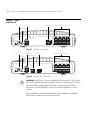
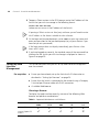
Switch — Rear
View Detail
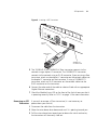
Figure 3 Switch 9 — rear view
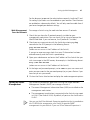
Figure 4 Switch 9 FX — rear view
WARNING: RJ-45 Ports. These are shielded RJ-45 data sockets. They cannot
be used as standard traditional telephone sockets, or to connect the unit to a
traditional PBX or public telephone network. Only connect RJ-45 data
connectors, network telephony systems, or network telephones to these
sockets.
Either shielded or unshielded data cables with shielded or unshielded
jacks can be connected to these data sockets.
12VDC
3.5A MAX
Power LED
10BASE-T/100BASE-TX Ports1000BASE-T PortConsole PortPower Socket
12VDC
3.5A MAX
Power LED
10BASE-T/100BASE-TX PortsSFP PortConsole PortPower Socket
100BASE-FX Port

Switch — Rear View Detail 17
10BASE-T/
100BASE-TX Ports
The Switch has 8 auto-negotiating 10BASE-T/100BASE-TX ports
configured as Auto MDI/MDI-X. These ports automatically provide the
appropriate connection. The default state for 10/100 Mbps ports is
auto-negotiation enabled, where the speed, duplex and flow control
modes are negotiated.
Alternatively, you can manually set these ports to 10BASE-T half duplex,
10BASE-T full duplex, 100BASE-TX half duplex, 100BASE-TX full duplex
and manually enable or disable flow control. The maximum segment
length is 100 m (328 ft) over Category 5 twisted pair cable.
If you disable auto-negotiation, Auto MDI/MDI-X will also be disabled.
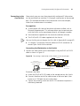
The Switch will supply up to 15.4W of power through ports 1, 2, 5 and 6
in conformance to the 802.3af specification. The Switch incorporates a
PoE Status LED on the front panel, which indicates when power is being
delivered to a device connected to one of these ports.
10BASE-T/
100BASE-TX/
1000BASE-T Port
The Switch 9 has one auto-negotiating
10BASE-T/100BASE-TX/1000BASE-T port configured as Auto MDI/MDI-X.
This port automatically provides the appropriate connection. The default
state for the 10/100/1000 Mbps port is auto-negotiation enabled, where
the speed, duplex and flow control modes are negotiated.
Alternatively, you can manually set these ports to 10BASE-T half duplex,
10BASE-T full duplex, 100BASE-TX half duplex, 100BASE-TX full duplex
or 1000BASE-T full duplex and manually enable or disable flow control.
The maximum segment length is 100 m (328 ft) over Category 5 twisted
pair cable.
If you disable auto-negotiation, Auto MDI/MDI-X will also be disabled.
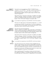
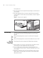
SFP Port The Switch 9 FX has one SFP (Small Form Factor Pluggable) port that
supports Gigabit Ethernet short-wave (SX) or long-wave (LX) fiber-optic
SFP transceivers, or Gigabit Ethernet 1000BASE-TX SFP transceivers. This
offers you the flexibility of using SFP transceivers to provide connectivity
between the Switch and a 1000 Mbps core network or to create a high
capacity aggregated link between two workgroups.
When using fiber-optic SFP transceivers, the only state for this port is
auto-negotiation enabled. As the speed and duplex modes are fixed by
the media type, only the flow control is negotiated with the link partner.

18 CHAPTER 1: INTRODUCING THE OFFICECONNECT MANAGED SWITCH 9 AND SWITCH 9FX
When an SFP module is inserted it has priority over the 100BASE-FX port.
The corresponding 100BASE-FX port is disabled when an SFP module is
present.
100BASE-FX Port The Switch 9 FX has one 100BASE-FX LC port. This is a 100 Mbps
fiber-optic port that can use standard multi-mode fiber-optic cable of up
to 2 kilometers (1.2 miles). It uses the standard duplex LC connector that
allows both the transmit and the receive fibers to be connected in the
same space as an RJ-45 port.
When an SFP module is inserted it has priority over the 100BASE-FX port.
The corresponding 100BASE-FX port is disabled when an SFP module is
present.
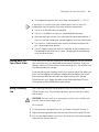
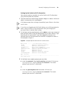
Console Port The console port allows you to connect a terminal and perform local
out-of-band management. The console port uses an RJ-45 to DB-9 null
modem cable (supplied with the Switch) and is set to 19200 baud, 8 data
bits, no parity and 1 stop bit.
The default configuration automatically detects any of the following baud
rates: 1200, 2400, 4800, 9600, 19200, 38400, 57600, 115200.
However, you must set the baud rate on your management device to
19200 baud if you want to view all the system initialization messages.
Power Socket The power adapter supplied with the Switch automatically adjusts its
power setting to any supply voltage in the range 100-240 VAC. Only use
the adapter provided with the Switch.

Default Settings 19
Default Settings Table 5 shows the default settings for the Switch:
Table 5 Default Settings
Feature Switch
IP Configuration Automatic by DHCP client
Port Status Enabled
Port Speed ■ 10BASE-T/100BASE-TX ports are
auto-negotiated
■ 10BASE-T/100BASE-TX/1000BASE-T port is
auto-negotiated
■ 100BASE-FX port is fixed at 100 Mbps
Duplex Mode ■ 10BASE-T/100BASE-TX port is auto-negotiated
■ 10BASE-T/100BASE-TX/1000BASE-T port is
auto-negotiated (half duplex or full duplex at
10/100 Mbps, full duplex only at 1000 Mbps)
■ 100BASE-FX port defaults to 100 Mbps
full-duplex mode (100 FD) and must be
manually set to half-duplex mode (100 HD) if
required.
Power over Ethernet Enabled (ports 1, 2,5 and 6)
Flow Control ■ Disabled in half duplex 10/100 ports
■ Auto-negotiated in full duplex 10/100 ports
■ Disabled for 10/100/1000 port
Broadcast Storm Control Enabled
Virtual LANs (VLANs) All ports belong to the untagged Default VLAN
(VLAN 1) with IEEE Std 802.1Q-1998 learning
operational
Multicast Filtering IGMP Filtering enabled
Rapid Spanning Tree Protocol Enabled
Spanning Tree Fast Start ■ Disabled on 10/100 ports
■ Disabled on 10/100/1000 port
Traffic Prioritization All ports prioritize NBX VoIP traffic (LAN and IP).
All ports set to “best effort” for all other traffic.
Port Security Disabled per port

20 CHAPTER 1: INTRODUCING THE OFFICECONNECT MANAGED SWITCH 9 AND SWITCH 9FX
If you initialize a Switch unit by selecting System > Control > Initialize in
the Web interface or by entering
system control initialize in
the Command Line Interface, the following settings are retained to allow
you to connect to and manage the Switch:
■ IP Address
■ Subnet Mask
■ Default Gateway
La pagina si sta caricando...
La pagina si sta caricando...
La pagina si sta caricando...
La pagina si sta caricando...
La pagina si sta caricando...
La pagina si sta caricando...
La pagina si sta caricando...
La pagina si sta caricando...
La pagina si sta caricando...
La pagina si sta caricando...
La pagina si sta caricando...
La pagina si sta caricando...
La pagina si sta caricando...
La pagina si sta caricando...
La pagina si sta caricando...
La pagina si sta caricando...
La pagina si sta caricando...
La pagina si sta caricando...
La pagina si sta caricando...
La pagina si sta caricando...
La pagina si sta caricando...
La pagina si sta caricando...
La pagina si sta caricando...
La pagina si sta caricando...
La pagina si sta caricando...
La pagina si sta caricando...
La pagina si sta caricando...
La pagina si sta caricando...
La pagina si sta caricando...
La pagina si sta caricando...
La pagina si sta caricando...
La pagina si sta caricando...
La pagina si sta caricando...
La pagina si sta caricando...
La pagina si sta caricando...
La pagina si sta caricando...
La pagina si sta caricando...
La pagina si sta caricando...
La pagina si sta caricando...
La pagina si sta caricando...
La pagina si sta caricando...
La pagina si sta caricando...
La pagina si sta caricando...
La pagina si sta caricando...
La pagina si sta caricando...
La pagina si sta caricando...
La pagina si sta caricando...
La pagina si sta caricando...
La pagina si sta caricando...
La pagina si sta caricando...
La pagina si sta caricando...
La pagina si sta caricando...
La pagina si sta caricando...
La pagina si sta caricando...
La pagina si sta caricando...
La pagina si sta caricando...
La pagina si sta caricando...
La pagina si sta caricando...
La pagina si sta caricando...
La pagina si sta caricando...
-
 1
1
-
 2
2
-
 3
3
-
 4
4
-
 5
5
-
 6
6
-
 7
7
-
 8
8
-
 9
9
-
 10
10
-
 11
11
-
 12
12
-
 13
13
-
 14
14
-
 15
15
-
 16
16
-
 17
17
-
 18
18
-
 19
19
-
 20
20
-
 21
21
-
 22
22
-
 23
23
-
 24
24
-
 25
25
-
 26
26
-
 27
27
-
 28
28
-
 29
29
-
 30
30
-
 31
31
-
 32
32
-
 33
33
-
 34
34
-
 35
35
-
 36
36
-
 37
37
-
 38
38
-
 39
39
-
 40
40
-
 41
41
-
 42
42
-
 43
43
-
 44
44
-
 45
45
-
 46
46
-
 47
47
-
 48
48
-
 49
49
-
 50
50
-
 51
51
-
 52
52
-
 53
53
-
 54
54
-
 55
55
-
 56
56
-
 57
57
-
 58
58
-
 59
59
-
 60
60
-
 61
61
-
 62
62
-
 63
63
-
 64
64
-
 65
65
-
 66
66
-
 67
67
-
 68
68
-
 69
69
-
 70
70
-
 71
71
-
 72
72
-
 73
73
-
 74
74
-
 75
75
-
 76
76
-
 77
77
-
 78
78
-
 79
79
-
 80
80


3com 3CR16708-91 Manuale utente
- Categoria
- Switch di rete
- Tipo
- Manuale utente
- Questo manuale è adatto anche per
in altre lingue
- English: 3com 3CR16708-91 User manual
Documenti correlati
-
3com AP9552 Hardware Installation Manual
-
-
3com 4210 26-PORT Manuale utente
-
-
3com 3CRWE675075 - 11a/b/g Wireless LAN Workgroup Bridge Manuale utente
-
-
-
-
-
Altri documenti
-
D-Link DES-1316 - Switch Manuale utente
-
Intellinet 24-Port Gigabit Ethernet PoE Web-Managed Switch with 4 Gigabit Combo Base-T/SFP Ports Manuale utente
-
-
-
Grandstream GWN7830 Guida d'installazione
-
HP 3C905B-TX Manuale utente
-
-
Intel 330T Manuale utente
-
Intellinet 508988 Istruzioni per l'uso
-