
EVCO S.p.A. | EV3 200 Web | 1043W24A3.00
www.evco.it
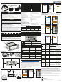
EV3 200 Web | Controllore - Gateway per una rete no a 10 strumenti
1/2
Per maggiori informazioni, consultare il manuale d'uso p/n 114J500I4 scaricabile dal sito www.evco.it o
scansiona il QR CODE.
SCANSIONA IL QR CODE E
LEGGI IL MANUALE UTENTE!
CONNESSIONI ELETTRICHE
PERICOLO
RISCHIO DI SHOCK ELETTRICO, ESPLOSIONE O ARCO ELETTRICO
• Diversi componenti del prodotto, compresi i circuiti stampati, funzionano a tensione pericolosa.
• Utilizzare esclusivamente apparecchiature di misurazione e attrezzi isolati elettricamente e
opportunamente tarati.
• Non aprire, smontare, riparare o modificare il prodotto.
• Prima di maneggiare il prodotto, indossare tutti i dispositivi di protezione individuali necessari.
• Non esporre l'apparecchiatura a sostanze liquide o agenti chimici.
• Utilizzare questo dispositivo e tutti i prodotti collegati solo alla tensione specificata.
• Non utilizzare questa apparecchiatura per funzioni critiche per la sicurezza.
IL MANCATO RISPETTO DI QUESTE ISTRUZIONI PROVOCHERÀ MORTE O GRAVI INFORTUNI.
PERICOLO
RISCHIO DI SHOCK ELETTRICO E INCENDIO
• Non utilizzare l'apparecchiatura con carichi superiori a quelli indicati nei dati tecnici.
• Non eccedere i range di temperatura e umidità indicati nei dati tecnici.
IL MANCATO RISPETTO DI QUESTE ISTRUZIONI PROVOCHERÀ MORTE O GRAVI INFORTUNI.
AVVERTIMENTO
FUNZIONAMENTO ANOMALO DELL'APPARECCHIATURA
• Eseguire il cablaggio con attenzione conformemente ai requisiti in materia di compatibilità elettromagnetica.
• Non mettere in funzione il prodotto con impostazioni o dati ignoti o errati.
• Verificare che il cablaggio sia corretto per le impostazioni.
• Usare cavi schermati per tutti cavi di segnali di I/O e di comunicazione.
• Ridurre il più possibile la lunghezza dei collegamenti ed evitare di avvolgerli intorno a parti collegate elettricamente.
• I cavi di segnale (Ingressi digitali, analogici, uscite analogiche, comunicazione e relative alimentazioni), i
cavi di potenza e di alimentazione dello strumento devono essere instradati separatamente.
• Prima di applicare l’alimentazione elettrica, verificare tutti i collegamenti del cablaggio.
• Non collegare fili a dei morsetti non utilizzati e/o a morsetti che riportano la dicitura “Nessuna connessione “(N.C.)”.
IL MANCATO RISPETTO DI QUESTE ISTRUZIONI PUÒ PROVOCARE MORTE, GRAVI INFORTUNI O
DANNI ALLE APPARECCHIATURE.
Cablaggio adeguato per alimentazione ed I/O SELV
Passo 5,08 mm (0.199 in.)
Ø 3.5 mm (0.14 in.)
mm2
AWG
0.2…2.5
24…14
0.2…2.5
24…14
0.25…2.5
22...14
2 x 0.25…1
2 x 22…18
2 x 0.2…1.5
2 x 24…16
2 x 0.2…1
2 x 24…18
2 x 0.5...1.5
2 x 20...16
mm
in.
7
0.28 C0.5...0.6
4.42...5.31
N•m
lb-in
0.25…2.5
22...14
AVVISO
APPARECCHIATURA NON FUNZIONANTE
• Per il collegamento delle sonde, degli ingressi digitali e della alimentazione, usare cavi con
lunghezza massima inferiore a 10 m (32,80 ft).
• Per il collegamento dell'alimentazione del controllore e delle uscite relè, usare cavi con
lunghezza massima inferiore a 10 m (32,80 ft.).
IL MANCATO RISPETTO DI QUESTE ISTRUZIONI PUÒ PROVOCARE DANNI ALLE APPARECCHIATURE.
DIMENSIONI
33 (1.30)
75 (2.95)
69 (2.71)
59 (2.32)
mm (in.
)
INSTALLAZIONE
71
(
2.7
9)
29 (1.14)
mm (in.)
40 (1.57) 40 (1.57)
mm (in.)
40 (1.57) 40 (1.57)
SCHEMA DI CONNESSIONE
1 2 3 4 5 6
12
13 14 15
Out2
A+
Out4
Out3
Out1
Alimentazione
Massimo 12 A
USB
LT
Pb1
Pb2
ID1
ID3
RS-485
EV3 200 Web
ON
12
12
13 14 15
RS-485
ETHERNET
ETHERNET
8 9 10 11 12
8 9 10 11 12
1 2 3 4 5 6
B- GND
LD3
LD1
LD2
LD4
ON
12
ON
12
LT
LT
TERMINALI
1-6 Uscita relè Out1 (Compressore) 13-14-15 Ingresso seriale RS-485
2-6 Uscita relè Out3 (Ventole) LT 1ON = Resistenza di terminazione inserita
3-6 Uscita relè Out4 (Sbrinamento) 2Riservato
4-6 Ingresso Alimentazione USB Ingresso USB 2.0 per comunicazione
5-6 Uscita relè Out2 (AUX)
ETHERNET
Connettore RJ45 per collegamento seriale
Ethernet
8-10 Ingresso digitale ID1
LED
LD1 Rosso Lampeggia a messaggi da sottorete
9-10 Ingresso digitale ID3 (se P4 = 0)
Ingresso sonda Pb3 (se P4 ≠ 0)
LD2 Verde Acceso fisso se connesso a EPoCA
LD3 Rosso Acceso fisso con Ethernet link-up
11-10
Ingresso analogico Pb1 (Temperatura)
LD4 Verde Acceso fisso con attività Ethernet
12-10
Ingresso analogico Pb2 (Evaporatore)
LED Spenti: Comunicazione assente
DATI TECNICI
Il prodotto è conforme alle seguenti norme
armonizzate:
EN60730-1 e EN60730-2-9
Costruzione del dispositivo: Dispositivo elettronico incorporato
Scopo del dispositivo: Dispositivo di comando di funzionamento
Tipo di azione: 1
Grado di inquinamento: 2
Categoria di sovratensione: III
Tensione impulsiva nominale: 4000 V
Alimentazione: 115...230 Vac, ±10%, 50/60 Hz
Consumo: 10 VA massimo
Condizioni operative ambientali:
-10 ... 50 °C (14 ... 122 °F) 10 … 90 % RH non condensante
Condizioni di trasporto e immagazzinamento:
-20 ... 70 °C (-4 ... 158 °F) 10 … 90 % RH non condensante
Classe del software: A
Protezione frontale ambientale: IP65
Orologio (rtc): Batteria al litio incorporata
Deriva orologio: ≤ 60 s/mese a 25 °C (77 °F)
Durata batteria: 30 giorni
Tempo di ricarica batteria: 24 h tramite alimentazione strumento
Memoria dati: 32 MB
Memoria dati per risorsa: ~2,7 MB
ALTRE INFORMAZIONI TECNICHE
Ingressi digitali: 2 ingressi digitali a contatto pulito
Ingressi analogici per temperatura: 2 ingressi analogici per sonde NTC
Uscita digitale a tensione non pericolosa (SELV): 4 uscite relè
Seriale: 1 seriale Ethernet RJ45 10/100 MAC
1 seriale USB
CARATTERISTICHE INGRESSI ANALOGICI
Default NTC 10 kΩ a 25
°C BETA 3435
PTC KTY 81-121
990 Ω a 25 °C RH Ingresso
digitale
Pb1
Sonda Temperatura
•--- --- ---
Pb2
Sonda Evaporatore
•--- --- ---
Range --- -40...105 °C
(-40...220 °F) --- --- ---
Risoluzione --- 0,1 °C (1 °F) --- --- ---
Impedenza d'ingresso --- 10 kΩ --- --- ---
CARATTERISTICHE USCITE DIGITALI
Default Descrizione Carico (a 250 Vac) Tipo di carico
Out1 Compressore SPDT 16 A Resistivo
Out2 AUX SPDT 5 A Resistivo
Out3 Ventole SPDT 5 A Resistivo
Out4 Non configurata SPDT 8 A Resistivo
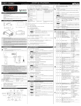
INTERFACCIA UTENTE
Tasto... Toccare e rilasciare per... Toccare per almeno 3 secondi per...
• Scorrere i valori verso l'alto
• Spostarsi all'interno del menu
Attivare sbrinamento manuale
• Scorrere i valori verso il basso
• Spostarsi all'interno del menu
Accedere al menu funzioni FNC (funzioni da tasto)
Attivare manualmente relè luce Accendere/Spegnere (stand-by) dispositivo
• Confermare i valori a display
• Impostare il setpoint Entrare nel menu parametri
Icona Accesa ssa Lampeggiante OFF
Compressore ON
• Ritardo protezione
compressore ON
• Modica setpoint in corso
Compressore OFF
• Sbrinamento ON
• Pre-sgocciolamento ON
• Ritardo sbrinamento ON
• Sgocciolamento ON
---
Ventole evaporatore ON
Ritardo attivazione ventole
evaporatore
ON
Ventole evaporatore OFF
Allarme HACCP registrato in
memoria
Nuovo allarme HACCP
registrato ---
Temperatura visualizzata in °C
--- • Sovra-riscaldamento ON
• Sovra-raffreddamento ON
Temperatura visualizzata in °F
---
• Funzione AUX ON
• Uscita digitale AUX ON --- Funziona AUX OFF
Risparmio energetico ON ---
Risparmio energetico OFF
Richiesta manutenzione
compressore
• Modica parametri in corso
• Accesso a menu FNC
(funzioni da tasto)
•
Collegamento con EVconnect
attivo
---
Dispositivo in OFF --- Dispositivo accesso
CONFIGURAZIONE COMUNICAZIONE REMOTA
La configurazione di EV3 200 Web, per collegamento con EPoCA, può avvenire in 2 modalità:
• Da PC (solo Windows), attraverso EPOCA.exe (in rete/ofine) scaricabile dal sito:
https://www.evco.it/assets/doc/EVCO-EV3200Web_congurator_for_EPoCA.zip;
• Da Smartphone/Tablet, attraverso l'APP EVLink Wi-Fi.
In entrambi i casi, i dispositivi devono essere visibili sulla rete locale. Se la rete locale richiede un
IP statico, utilizzare la configurazione tramite cavo USB micro-B.
In caso di utilizzo in sottorete, configurare il parametro BLE per ogni strumento da 1 a 10, prima
di effettuare la ricerca sulla rete.
NOTA: Per maggiori informazioni riguardanti le possibili congurazioni della comunicazione
remota, scansiona il QR code presente in questo foglio istruzioni e leggi il manuale utente.
Congurazione tramite PC (collegamento con
cavo USB micro-B)
1. Collegare il cavo USB micro-B dal PC allo strumento;
2. Assicurarsi di avere installato nel PC EPoCA.exe;
3. Avviare EPoCA.exe;
4. Impostare i dati del Plant e del Device, salvare la congurazione premendo Save Cong. e
proseguire premendo Next;
3
Next
Prev
1. Plant Configuration
EPOCA
Plant Name:
Plant Password:
Plant Category:
Device Name:
Serial Code:
Plant ID:
Build:
Last Reset:
Mac address:
Internet Status:
Save Config.
Export plant fileUpload plant file
Erase Config.
4 5
Next
Prev
2. Date and Time
EPOCA
Day, NN MM YYYY hh:mm:ss
Daylight saving time Addr. 1
Off
Set local time
Next
Prev
3. Controllers
EPOCA
Autoaddress
Com1
On Line
On Line
Off Line
Off Line
Off Line
Off Line
Off Line
Off Line
Off Line
Off Line
Name Name
Name
Addr. 2
Addr. 3
Addr. 4
Addr. 5
Addr. 6
Addr.7
Addr. 8
Addr. 9
Addr. 10
Name
Name
Name
Name
Name
Name
Name
Name
Name
5. Impostare data, ora e fuso orario usato e premere Next;
6. Impostare il nome delle risorse collegate in RS-485 al EV3 200 Web e premere Next;
7. Impostare il tipo di indirizzo IP e premere Next;
8. Premere Congure per terminare la fase di congurazione dello strumento.
6 7
Next
Prev
4. IP Address
EPOCA
IP address:
Dynamic
Next
Prev
EPOCA
Configure
Next
Prev
4. IP Address
EPOCA
Static
IP address
Netmask
Gateway
Dns 1
Dns 2
0.0.0.0
0.0.0.0
0.0.0.0
0.0.0.0
0.0.0.0
6
Congurazione tramite PC (
Collegamento tramite cavo Ethernet su modem)
1. Assicurarsi di avere installato nel PC EPoCA.exe;
2. Avviare EPoCA.exe, il programma scansiona la rete locale LAN a cui è collegato il PC, per
rilevare gli strumenti;
3. Selezionare lo strumento da congurare e premere Next;
4. Impostare i dati del Plant e del Device, salvare la congurazione premendo Save Cong. e
proseguire premendo Next;
3 4
Next
Device selection
Device web page
EPOCA
EPOCAAXXXXX
Next
Prev
1. Plant Configuration
EPOCA
Plant Name:
Password:
Plant Category:
Device Name:
Serial Code:
Plant ID:
Build:
Last Reset:
Mac address:
Internet Status:
Save Config.
Export plant fileUpload plant file
Erase Config.
5. Impostare data, ora e fuso orario usato e premere Next;
6. Impostare il nome delle risorse collegate in RS-485 al EV3 200 Web e premere Next;
5 6
Next
Prev
2. Date and Time
EPOCA
Day, NN MM YYYY hh:mm:ss
Daylight saving time Addr. 1
Off
Set local time
Next
Prev
3. Controllers
EPOCA
Autoaddress
Com1
On Line
On Line
Off Line
Off Line
Off Line
Off Line
Off Line
Off Line
Off Line
Off Line
Name Name
Name
Addr. 2
Addr. 3
Addr. 4
Addr. 5
Addr. 6
Addr.7
Addr. 8
Addr. 9
Addr. 10
Name
Name
Name
Name
Name
Name
Name
Name
Name
Impostare il tipo di indirizzo IP e premere Next;
7. Premere Congure per terminare la fase di congurazione dello strumento.
7 8
Next
Prev
4. IP Address
EPOCA
IP address:
Dynamic
Next
Prev
EPOCA
Configure
Cod.
Descrizione Causa Effetti Risoluzione
Pr1
Sonda in
errore
• Sonda non
funzionante
• Sonda collegata
non correttamente
• Tipo sonda non
corretto
• Visualizzazione codice Pr1
• Uscita allarme ON
• Regolazione compressore in
funzione di C4 e C5
• Sbrinamento sospeso • Controllare il tipo di
sonda (PO)
• Controllare il cablaggio
sonda
• Cambiare il tipo di sonda
Pr2
• Visualizzazione codice Pr2
• Uscita allarme ON
• Se P4 = 1, sbrinamento attivo per
un tempo d3
Pr3
• Visualizzazione codice Pr3
• Nessun effetto sulla regolazione
rtc
Allarme
orologio
Allarme orologio
(RTC) non
funzionante
Funzioni collegate all'orologio non
presenti o non sincronizzate con
l'orario effettivo
Impostare l'ora corretta.
Se l'errore permane
sostituire lo strumento
(batteria RTC scarica)
AL
Allarme di
bassa temp.
Pb1
Temperatura Pb1 > A1
per un tempo = A7
• Visualizzazione codice AL
• Nessun effetto sulla regolazione
Attendere che la temp. letta
Pb1 < (A1-A11)
AH
Allarme di
alta temp.
Pb1
Temperatura Pb1 > A4
per un tempo = A7
• Visualizzazione codice AH
• Nessun effetto sulla regolazione
Attendere che la temp. letta
Pb1 > (A4+A11)
id
Allarme porta
aperta
ID ON per un
tempo > i2
• Visualizzazione codice id
• Blocca regolatori in base alla
funzione attiva in iC1 = 7, 8 o 9
• Se i2 = -1 l' allarme è
disabilitato;
• Vericare i2 e iP1
PF
Allarme
mancanza
tensione
Mancanza di
tensione per un
tempo > A10 Registrazione codice PF Verificare il cablaggio
alimentazione
COH
Segnalazione
condensatore
surriscaldato
Temp. cond. > C6 • Visualizzazione codice COH
• Nessun effetto sulla regolazione Verificare C6
CSd
Allarme alta
cond.
Temp. cond. > C7
per un tempo = C8 • Visualizzazione codice CSd
• Blocca compressore
• Spegnere e accendere lo
strumento;
• Vericare C7 e C8
iA
Allarme
ingresso
multifunzione
ID ON (iC1 = 2) per
un tempo = i5
• Visualizzazione codice iA
• Nessun effetto sulla regolazione Verificare i5 e i6
CtH
Allarme
termica
compr.
ID ON
(iC1 = 5) Il regolatore conta dal primo il
numero di eventi i8 nel tempo i7
• Se i7 = 0 il riarmo è
sempre automatico
• Vericare i5 e i6
th
Allarme
termica
globale
ID ON
(iC1 = 5) Il regolatore conta dal primo il
numero di eventi i8 nel tempo i7
• Spegnere e accendere lo
strumento;
• Verificare i5 e i6
dFd
Allarme
timeout
sbrinamento
Sbrinamento
terminato per
timeout anziché per
raggiungimento
temperatura d2
• Visualizzazione codice dFd
• Nessun effetto sulla regolazione
• Toccare un tasto qualsiasi
• Vericare d2, d3 e d11
CONSIDERA L'AMBIENTE
Si prega di leggere e conservare il documento
SMALTIMENTO
Il dispositivo deve essere smaltito secondo le normative locali in merito alla raccolta
delle apparecchiature elettriche ed elettroniche.
Declinazione di responsabilità
La presente documentazione è proprietà esclusiva di EVCO. Contiene la descrizione
generale e/o le caratteristiche tecniche per le prestazioni dei prodotti qui contenuti. Questa
documentazione non è destinata e non deve essere utilizzata per determinare l'adeguatezza o
l'affidabilità di questi prodotti relativamente alle specifiche applicazioni dell'utente. Ogni utente o
specialista di integrazione deve condurre le proprie analisi complete e appropriate del rischio,
effettuare la valutazione e il test dei prodotti in relazione all'uso o all'applicazione specifica.
Né EVCO né qualunque associata o filiale deve essere ritenuta responsabile o perseguibile per il
cattivo uso delle informazioni ivi contenute. Gli utenti possono inviarci commenti e suggerimenti
per migliorare o correggere questa pubblicazione.
EVCO adotta una politica di continuo sviluppo. Pertanto EVCO si riserva il diritto di effettuare
modifiche e miglioramenti a qualsiasi prodotto descritto nel presente documento senza previo
preavviso.
I dati tecnici presenti nel manuale possono subire modifiche senza obbligo di preavviso.

www.evco.it
2/2
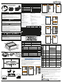
EV3 200 Web | Controller - Gateway for a network of up to 10 devices
EVCO S.p.A. | EV3 200 Web | 1043W24A3.00
EVCO S.p.A.
Via Feltre 81, 32036, Sedico (BL) ITALIA
Telephone: 0437 8422 | Fax: 0437 83648
Email: [email protected] | Web: www.evco.it
Disclaimer
This document is the exclusive property of EVCO. It contains a general description and/or a description of
the technical specifications for the services offered by the products listed herein. This document should not
be used to determine the suitability or reliability of these products in relation to specific user applications.
Each user or integration specialist should conduct their own complete and appropriate risk analysis, in
addition to carrying out a product evaluation and test in relation to its specific application or use. Users
can send us comments and suggestions on how to improve or correct this publication.
Neither EVCO nor any of its associates or subsidiaries shall be held responsible or liable for improper use
of the information contained herein.
EVCO has a policy of continuous development. Therefore, EVCO reserves the right to make changes and
improvements to any product described in this document without prior notice.
The technical data in this manual is subject to change without prior notice.
Consider the environment
Please consider the environment before printing this document.
Disposal
The device must be disposed of in accordance with local regulations regarding the
collection of electrical and electronic appliances.
For further information, consult the user manual p/n 114J500E4
downloadable from the website
www.evco.it or scan the QR CODE.
SCAN THE QR CODE AND
READ THE USER MANUAL!
ELECTRICAL CONNECTIONS
DANGER
RISK OF ELECTRIC SHOCK, EXPLOSION OR ELECTRIC ARC
• Various product components, including the printed circuits, run at hazardous voltage levels.
• Only use electrically insulated and suitably calibrated measuring devices and equipment.
• Do not open, disassemble, repair or modify the product.
• Before handling the product, make sure you are wearing all the necessary personal protective
equipment (PPE).
• Do not expose the equipment to liquids or chemicals.
• Use this device and all parts connected to it at the specified voltage only.
• Do not use this equipment for critical safety functions.
FAILURE TO FOLLOW THESE INSTRUCTIONS WILL RESULT IN DEATH OR
SERIOUS INJURY.
DANGER
RISK OF ELECTRIC SHOCK AND FIRE
• Do not use the device with loads greater than those indicated in the technical specifications.
• Do not exceed the temperature and humidity ranges indicated in the technical specifications.
FAILURE TO FOLLOW THESE INSTRUCTIONS WILL RESULT IN DEATH OR
SERIOUS INJURY.
WARNING
MALFUNCTIONING OF THE EQUIPMENT
• Perform the wiring carefully, in compliance with electromagnetic compatibility and safety
requirements.
• Do not operate the product with unknown or incorrect settings or data.
• Make sure the wiring is correct for the final application.
• Use shielded cables for all I/O signal and communication cables.
• Minimise the length of the connections as much as possible and avoid winding the cables
around electrically connected parts.
• The signal cables (analogue and digital inputs, communication and corresponding power
supplies), power cables and power supply cables for the device must be routed separately.
• Before applying the power supply, check all the wiring connections.
• Do not connect wires to unused terminals and/or to terminals labelled “No connection “(N.C.)”.
FAILURE TO FOLLOW THESE INSTRUCTIONS CAN RESULT IN DEATH, SERIOUS
INJURY, OR EQUIPMENT DAMAGE.
Suitable wiring for power supply and I/O SELV
Passo 5,08 mm (0.199 in.)
Ø 3.5 mm (0.14 in.)
mm2
AWG
0.2…2.5
24…14
0.2…2.5
24…14
0.25…2.5
22...14
2 x 0.25…1
2 x 22…18
2 x 0.2…1.5
2 x 24…16
2 x 0.2…1
2 x 24…18
2 x 0.5...1.5
2 x 20...16
mm
in.
7
0.28 C0.5...0.6
4.42...5.31
N•m
lb-in
0.25…2.5
22...14
NOTICE
INOPERABLE DEVICE
• When connecting the probes, the digital inputs and the power supply, use cables with a
maximum length of 10 m (32.80 ft).
• When connecting the power supply of the controller and the relay outputs, use cables with
a maximum length of 10 m (32.80 ft.).
FAILURE TO FOLLOW THESE INSTRUCTIONS CAN RESULT EQUIPMENT DAMAGE
.
DIMENSIONS
33 (1.30)
75 (2.95)
69 (2.71)
59 (2.32)
mm (in.
)
INSTALLATION
71
(
2.7
9)
29 (1.14)
mm (in.)
40 (1.57) 40 (1.57)
mm (in.)
40 (1.57) 40 (1.57)
WIRING DIAGRAM
1 2 3 4 5 6
12
13 14 15
Out2
A+
Out4
Out3
Out1
Power Supply
Maximum 12 A
USB
LT
Pb1
Pb2
ID1
ID3
RS-485
EV3 200 Web
ON
12
12
13 14 15
RS-485
ETHERNET
ETHERNET
8 9 10 11 12
8 9 10 11 12
1 2 3 4 5 6
B- GND
LD3
LD1
LD2
LD4
ON
12
ON
12
LT
LT
TERMINALS
1-6 Relay output Out1 (Compressor) 13-14-15 RS-485 serial input
2-6 Relay output Out3 (Fans) LT 1ON = Termination resistor inserted
3-6 Relay output Out4 (Defrost) 2Reserved
4-6 Power supply input USB USB 2.0 input for communication
5-6 Relay output Out2 (AUX)
ETHERNET
RJ45 connector to connect to Ethernet
serial port
8-10 Digital input ID1
LED
LD1 Red
Flashes with messages from
subnetwork
9-10 Digital input ID3 (if P4=0)
Probe input Pb3 (if P4 ≠ 0)
LD2 Green Stays on if connected to EPoCA
LD3 Red Stays on with Ethernet link-up
11-10 Analogue input Pb1 (Temperature) LD4 Green Stays on with Ethernet activity
12-10 Analogue input Pb2 (Evaporator) LED Spenti: No communication
TECHNICAL SPECIFICATIONS
The product complies with the following
harmonised standards:
EN60730-1 and EN60730-2-9
Device construction: Built-in electronic device
Device purpose: Operating control device
Type of action: 1
Pollution category: 2
Overvoltage category: III
Rated impulse withstand voltage: 4000 V
Power supply: 115...230 Vac, ±10%, 50/60 Hz
Consumption: 10 VA maximum
Ambient operating conditions: -10 ... 50 °C (14 ... 122 °F) 10 … 90 % RH non-condensing
Transportation and storage conditions: -20 ... 70 °C (-4 ... 158 °F) 10 … 90 % RH non-condensing
Software class: A
Environmental front protection: IP65
Clock (RTC): Built-in lithium battery
Clock drift: ≤ 60 s/month at 25 °C (77 °F)
Battery life: 30 days
Battery charging time: 24 h through device’s power supply
Data memory: 32 MB
Data memory per device: ~2.7 MB
OTHER TECHNICAL INFORMATION
Digital inputs: 2 voltage-free digital inputs
Analogue inputs for temperature: 2 analogue inputs for NTC probes
Digital output with non-hazardous voltage (SELV): 4 relay outputs
Serial: 1 Ethernet RJ45 10/100 MAC serial port
1 USB serial port
ANALOGUE INPUT FEATURES
Default NTC 10 kΩ at 25
°C BETA 3435
PTC KTY 81-121
990 Ω at 25 °C RH Digital
input
Pb1
Probe Temperature
•--- --- ---
Pb2
Probe Evaporator
•--- --- ---
Range --- -40...105 °C
(-40...220 °F) --- --- ---
Resolution --- 0.1 °C (1 °F) --- --- ---
Input impedance --- 10 kΩ --- --- ---
DIGITAL OUTPUT FEATURES
Default Description Load (at 250 Vac) Type of load
Out1 Compressor SPDT 16 A Resistive
Out2 AUX SPDT 5 A Resistive
Out3 Fans SPDT 5 A Resistive
Out4 Not configured SPDT 8 A Resistive
USER INTERFACE
Key... Press once... Hold down...
• Scroll up through values
• Move within a menu Activate manual defrost
• Scroll down through values
• Move within a menu
Access the FNC functions menu (functions activated
by key)
Manually activate the light relay Switch the device on/off (stand-by)
• Conrm values on the display
• Set the setpoint Enter the parameter menu
Icon ON... Flashing... OFF...
Compressor ON
• Protection delay compressor ON
• Setpoint being changed
Compressor OFF
• Defrost ON
• Pre-dripping ON
• Defrost delay ON
• Dripping ON ---
Evaporator fans ON
Evaporator fan activation delay ON
Evaporator fans OFF
HACCP alarm saved New HACCP alarm recorded ---
Temperature displayed in °C --- • Over-heating ON
• Over-cooling ON
Temperature displayed in °F ---
• AUX function ON
• AUX digital output ON --- AUX function OFF
Energy saving ON --- Energy saving OFF
Compressor maintenance
request
• Parameters being changed
• Access to FNC menu (functions activated by key)
• Active connection with EVconnect
---
Device off --- Device on
REMOTE COMMUNICATION CONFIGURATION
EV3 200 Web can be configured to connect with EPoCA in two different ways:
•
From a PC (Windows only) through EPoCA.exe (online/ofine) which can be downloaded from
the website: https://www.evco.it/assets/doc/EVCO-EV3200Web_congurator_for_EPoCA.zip
• From a smartphone/tablet using the EVLink Wi-Fi app.
In both cases, the devices must be visible on the local network. If the local network requires a
static IP address, configure using the micro-B USB cable.
If used in a subnetwork, configure the BLE parameter for every device from 1 to 10 before
searching on the network.
NOTE: For more information regarding the possible congurations of remote communication,
scan the QR code in this instruction sheet and read the user manual.
Conguration using PC (
Connecting using a micro-B USB cable)
1. Connect the micro-B USB cable from the PC to the device;
2. Make sure EPoCA.exe has been installed in the PC;
3. Boot up EPoCA.exe;
4. Set the Plant and Device data, save the conguration by pressing Save Cong. and continue
by pressing Next;
3
Next
Prev
1. Plant Configuration
EPOCA
Plant Name:
Plant Password:
Plant Category:
Device Name:
Serial Code:
Plant ID:
Build:
Last Reset:
Mac address:
Internet Status:
Save Config.
Export plant fileUpload plant file
Erase Config.
4 5
Next
Prev
2. Date and Time
EPOCA
Day, NN MM YYYY hh:mm:ss
Daylight saving time Addr. 1
Off
Set local time
Next
Prev
3. Controllers
EPOCA
Autoaddress
Com1
On Line
On Line
Off Line
Off Line
Off Line
Off Line
Off Line
Off Line
Off Line
Off Line
Name Name
Name
Addr. 2
Addr. 3
Addr. 4
Addr. 5
Addr. 6
Addr.7
Addr. 8
Addr. 9
Addr. 10
Name
Name
Name
Name
Name
Name
Name
Name
Name
5. Set the date, time and local time used and press Next;
6. Set the name of the controllers connected via RS-485 to EV3 200 Web and press Next;
7. Set the type of IP address and press Next;
8. Press Congure to complete conguration of the device.
6 7
Next
Prev
4. IP Address
EPOCA
IP address:
Dynamic
Next
Prev
EPOCA
Configure
Next
Prev
4. IP Address
EPOCA
Static
IP address
Netmask
Gateway
Dns 1
Dns 2
0.0.0.0
0.0.0.0
0.0.0.0
0.0.0.0
0.0.0.0
6
Conguration using PC (Connecting using an Ethernet cable with connection to modem)
1. Make sure EPoCA.exe has been installed in the PC;
2. Boot up EPoCA.exe, the programme scans the local network (LAN) which the PC is
connected to to detect the devices;
3. Select the device to congure and press Next;
4. Set the Plant and Device data, save the conguration by pressing Save Cong. and continue
by pressing Next;
3 4
Next
Device selection
Device web page
EPOCA
EPOCAAXXXXX
Next
Prev
1. Plant Configuration
EPOCA
Plant Name:
Password:
Plant Category:
Device Name:
Serial Code:
Plant ID:
Build:
Last Reset:
Mac address:
Internet Status:
Save Config.
Export plant fileUpload plant file
Erase Config.
5. Set the date, time and local time used and press Next;
6. Set the name of the controllers connected via RS-485 to EV3 200 Web and press Next;
5 6
Next
Prev
2. Date and Time
EPOCA
Day, NN MM YYYY hh:mm:ss
Daylight saving time Addr. 1
Off
Set local time
Next
Prev
3. Controllers
EPOCA
Autoaddress
Com1
On Line
On Line
Off Line
Off Line
Off Line
Off Line
Off Line
Off Line
Off Line
Off Line
Name Name
Name
Addr. 2
Addr. 3
Addr. 4
Addr. 5
Addr. 6
Addr.7
Addr. 8
Addr. 9
Addr. 10
Name
Name
Name
Name
Name
Name
Name
Name
Name
Set the type of IP address and press Next;
7. Press Congure to complete conguration of the device.
7 8
Next
Prev
4. IP Address
EPOCA
IP address:
Dynamic
Next
Prev
EPOCA
Configure
Cod.
Description Cause Effects Resolution
Pr1
Probe error
• Probe not working
• Probe incorrectly
connected
• Incorrect type of
probe
• Code Pr1 displayed
• Alarm output ON
• Compressor regulated
according to C4 and C5
• Defrost suspended
• Check the type of probe
(PO)
• Check probe wiring
• Change type of probe
Pr2
• Code Pr2 displayed
• Alarm output ON
• If P4 = 1, defrost active for time d3
Pr3
• Code Pr3 displayed
• No effect on regulation
rtc
Clock alarm Clock (RTC) alarm
not working
Clock-connected functions not
present or not synchronised with
the actual time
Set the right time.
If the error persists, replace
the device (RTC battery dead)
AL
Low
temperature
alarm Pb1
Temperature Pb1 >
A1 for a time = A7
• Code AL displayed
• No effect on regulation
Wait until the temperature
read by Pb1 goes below the
alarm threshold (A1-A11)
AH
High
temperature
alarm Pb1
Temperature Pb1 >
A4 for a time = A7
• Code AH displayed
• No effect on regulation
Wait until the temperature
read by Pb1 goes above the
alarm threshold (A4+A11)
id
Door open
alarm
Digital input
activated for a
time > i2
• Code id displayed
• Regulators blocked depending on
the current function in iC1 = 7, 8 or 9
• If i2 = -1 the alarm is
disabled;
• Check i2 and iP1
PF
Power outage
alarm
Power outage for
longer than A10 Code PF is recorded Check the power supply
wiring
COH
Cond. overheat
signal
Condenser
temperature > C6
• Code COH displayed
• No effect on regulation Check C6
CSd
High
condensation
alarm
Condenser
temperature > C7
for a time = C8
• Code CSd displayed
• Compressor locked
• Switch the device off then
on again;
• Check C7 and C8
iA
Multi-
purpose
input alarm
Digital input
activated (iC1 = 2)
for a time = i5
• Code iA displayed
• No effect on regulation Check i5 and i6
CtH
Compressor
thermal
switch alarm
Digital input
activated (iC1 = 5)
The regulator counts the number
of events i8 in the time i7 from
the rst one
• If i7 = 0 alarm is always
automatically reset
• Check i5 and i6
th
Thermal
switch global
alarm
Digital input
activated (iC1 = 5)
The regulator counts the number
of events i8 in the time i7 from
the rst one
• Switch the device off then
on again;
• Check i5 and i6
dFd
Defrost
timeout
alarm
Defrost terminated
due to timeout and
not to reaching
temperature d2
• Code dFd displayed
• No effect on regulation
• Touch any key
• Check d2, d3 and d11
-
 1
1
-
 2
2


Evco EV3W24N9R Instructions Sheet
- Tipo
- Instructions Sheet
- Questo manuale è adatto anche per
Documenti correlati
-
 Evco EV3W24N9RRH Guida d'installazione
-
 Evco EV3W01N9R Guida d'installazione
-
 Evco EV3294Z3 Instructions Sheet
-
 Evco EV3B81N9 Instructions Sheet
-
 Evco EVCMC37DJ2E Guida d'installazione
-
 Evco EV3423M3 Instructions Sheet
-
 Evco EVCMC689N9EH Guida d'installazione
-
 Evco EV3411M3 Instructions Sheet
-
 Evco EVCMC689N9EH Guida d'installazione
-
 Evco EV3B73N9 Instructions Sheet


Altri documenti
-
GGM Gastro BRF207D#2#SG12 Manuale del proprietario
-
 Olimpia Splendid SiOS control Guida d'installazione
-
Omega CN32Pt, CN16Pt, CN16PtD, CN8Pt, CN8PtD Manuale del proprietario
-
Samsung SNS-110P Manuale utente
-
Dell Stud Sensor MP2000 Manuale utente
-
Ascon tecnologic X36P Manuale del proprietario
-
