
www.quikoitaly.com
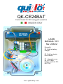
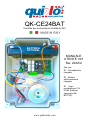
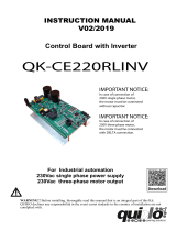
QK-CE24BAT
Control board for 24V swing gate operators
USER
MANUAL V01
Sw: 2432/2
Now with:
! Built in battery
charger
! Built in electric
lock module
! Apposite room
for 12V 2.6Ah
battery (optional QK-
BATT26)
OPTIONAL
BATTERY

www.quikoitaly.com
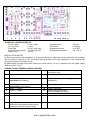
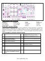
1 2 3 4 5 6 7 8 9 10 11 12 13 14 15 16 17
TECHNICAL CHARACTERISTICS
Power supply 24 AC, 100W Operating time 120 sec.
No. of motors 2 x 24V Pause time 15-60 sec.
Flash light 24V AC 10W max Displacement time 3-10 SEC
Photocell power supply 12 V DC 8W max Operating temperature -30 +70 °C
Battery input 14V DC
INSTALLATION NOTES
A) Before proceeding with installation, fit a magneto-thermal or differential switch upstream of the system
with a maximum capacity of 10A. The switch must guarantee omni polar separation of the contacts with
an opening distance of at least 3 mm.
B) Differentiate and keep the power cables (min cross-section 1.5 mm2) separate from the signal cables
which may be 0.5 mm2.
CONNECTIONS (TERMINAL BOARD LEGEND)
1
Input 0V AC
10
COMMON for NEGATIVE of flashing lamp
and Electric lock
2
Input 20VAC
11
Electric lock output 12Vdc 15W
3
Battery positive input
(red faston from battery)
12
Output 12V DC for power supply and
accessories
4
Battery negative input
(black faston from battery)
13
Common
5
Motor 1 + output
14
START input (NO)
6
Motor 2 - output
15
PHOTOCELL input (NC)
(can be disabled with DIP6)
7
Motor 2 + output
16
COMMON and ANTENNA SCREEN
8
Motor 2 – output
17
ANTENNA SIGNAL
9
Flash light POSITIVE output 24V DC
10W max (relay flashes quickly during
opening and slowly during closing).
18

www.quikoitaly.com
IMPORTANT: THE CONTROL BOARD WILL STOP THE MOTION OF THE GEARMOTORS WHEN THESE HAVE
REACHED THE MECHANICAL LIMIT SWITCHES / GROUND STOPPERS AT THE END OF THE OPENING OR
CLOSING MANOEUVRES
DIP SWITCH SETTING
DIP
ON
OFF
DIP1
(If DIP2 is in OFF) COMMUNITY MODE (after the
first Start signal it doesn't accept other start signals
during opening. A Start signal during pause causes
a recharge of pause time)
(If Dip2 is in ON) STEP BY STEP WITH
AUTOMATIC CLOSING (a start signal during
opening causes a stop. A start signal during pause
causes a stop. A start signal during closing causes a
re-opening)
RESIDENTIAL if DIP2 is in OFF.
DIP2
STEP BY STEP WITHOUT AUTOMATIC CLOSING
(open-stop-close-stop-open...)
RESIDENTIAL
(open-stop-close-open) After STOP,
PAUSE or START from tx the gate closes
automatically after pause time
DIP3
PAUSE time 60 seconds (function of rapid closing)
PAUSE time 15 seconds
DIP4
Displacement time 10 SEC
Displacement time 3 SEC
DIP5
1 motor functioning
2 motors functioning
DIP 6
Disables photocell input
Enables photocell input
OBSTACLE SENSING TRIMMERS AMPMOT1-AMPMOT2
By means of the trimmers AMPMOT1 and AMPMOT2 the intervention of the obstacle sensing of every motor can be
adjusted. The intervention of the obstacle sensing stops the motion (moving the trimmers clockwise increases the
strength necessary to obstacle sensing to stop the motion of the gate). If backup battery is being used, make sure to set
the trimmers so that the system is stopping the gate properly when touching ground stoppers at the end of opening and
closing manoeuvres.
FINAL CHECKS AND TESTING
Before powering the control unit, check the following:
• Check that the dip switches have been set correctly (by default ALL DIPs are OFF)
• Check the electrical connections; improper connection may cause damage to the control unit or the operator.
• POWER THE DEVICE
• Check that LEDs of the security devices are ON and LEDs START are OFF
• Check that when passing across the range of the photocells, the corresponding LED switches off.
• Check that the gate is closed and that the motors are locked and ready for operation. Remove any obstacles from
the range of action of the gate.
• Power the device and pass to the code learning and the programming phase.
RADIO RECEIVER
The control unit version is supplied complete with receiver with an operating frequency of 433.92 MHz and it is fitted with
a circuit for decoding Rolling-code remote controls (max. 200 codes).
LEARNING OF NEW CODES (to be carried out with closed gate):
Press once P1 button on control board, the programming LED switches on to indicate that the receiver is ready to learn
the START key of a remote control. Now you can press one of the keys of a transmitter. The LED flashes once to
indicate that the new code has been learned (if not, go first through the “memory reset” phase). Pressing again P1 button
more remote controls can be learned one after the other.
MEMORY RESET
When all codes need to be deleted, press P1 button on control board(the red LED switches on) and keep it pressed until
the LED switches off again. When the button is released the LED flashes 3 times (which indicates that the memory is
empty) and now pressing P1 again, the system is ready to learn once again a remote control.

www.quikoitaly.com
FAST RE-CLOSING FUNCTION (DIP3 = ON):
With this function you can reduce pause time to 3 seconds from intervention and clearing of the
photocells. To enable this function set DIP3 in ON position
INCREASED PAUSE TIME (DIP 3= ON )
Putting in ON the DIP 3, pause time increases from 15 to 60 seconds
EMERGENCY BATTERY SETTINGS: Make sure to connect + and – of battery to the proper connectors
fo control board: a wrong connection may damage the board. The control unit is equipped with battery
charger. It can operate the system in case of emergency with only one 12V battery, and detect
automatically when the system is battery operated (the microprocessor recognizes the emergency status
and adapt to the situation, switches the flash light off in order to save energy and carry out about 10
cycles with a battery of 2,6Ah).
1 MOTOR FUNCTIONING (DIP 5=ON ):
Putting In On the Dip 5 The Equipment Works With MOTOR 1 only
TROUBLESHOOTING
Before any installation or maintenance operation, ensure that the power supply has been cut !!
FAULT
POSSIBLE CAUSES AND SOLUTIONS
The operator does not
open or re-close
Check if the safety LEDs are ON and the LED of START is OFF
LEDs START are always
ON
Check that START input is connected to normally open contact
DIP remote control is
learned but doesn’t
function properly
Check that at least two DIP are in ON position (both combination all
ON and all OFF is not accepted for safety reasons)
Motor starts but stops
immediately after
Check that trimmer AMPMOT1 and AMPMOT2 is not at its
minimum level and that gate has not too much friction
The transmitter has a short
range
Check that the antenna is positioned properly (screen = terminal 16,
signal = terminal 17). Check that there are no sources of disturbance
nearby which limit the range.
WARNINGS
During the connections the power supply must be switched off
The control unit must be used rigorously respecting the technical safety standards. Installation and/or
maintenance must be carried out by qualified personnel in compliance with the provisions of the laws in
force. The manufacturer cannot be held responsible for damage caused by improper and/or irrational use.
A wrong installation or improper use of the products can compromise the safety of the unit. All materials
have to be kept far from the children since they can be dangerous
EC DECLARATION OF CONFORMITY
(EEC directive 89/392, annex II, part B) the manufacturer declares that the product QK-CE24BAT is in
conformity with EECC Directives 89/336/EEC, 92/31/EEC, 93/68/EEC on the electromagnetic
compatibility and that following harmonised standards have been applied: EN60335-1, EN60204-1,
EN55014, EN6100-3-2, EN 6100-3-3, EN 6100-4-2, EN 6100-4-4, ENV50140, EN50081-1, EN50082-1.
Moreover the manufacturer declares that it is not permitted to operate the products until the machine in
which they will be incorporated or of which they will become components has been identified and its
conformity with the provisions set out in Directive 89/392 /EEC and the national legislation has been
declared, i.e. until the products as set forth in this declaration form a single unit with the final machine.

www.quikoitaly.com
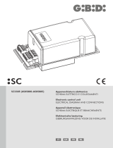
QK-CE24BAT
Centrale per automazioni a battente 24V
MANUALE
UTENTE V01
Sw: 2432/2
Ora con:
! Caricabatterie
integrato
! Modulo
elettroserratura
integrato
! Vano
portabatteria 12V
2.6Ah (batteria
opzionale QK-
BATT26)
BATTERIA
OPTIONAL

www.quikoitaly.com
1 2 3 4 5 6 7 8 9 10 11 12 13 14 15 16 17
CARATTERISTICHE TECNICHE
Alimentazione 24 VCA 100W T lavoro 120 sec.
N° motori 2 x 24V T pausa 15-60 secondi
Lampeggiante 24 Vca 10Wmax T sfasamento 3-10 SEC
Alim. Fotocellule 12 Vcc 8W Max T° utilizzo -30+70°C
Ingresso batteria 14VCC Serratura 12vcc 15W
NOTE PER L’INSTALLAZIONE
A) Prima di procedere con l’installazione bisogna predisporre a monte dell’impianto un interruttore
magneto termico o differenziale con portata massima di 10A. L’interruttore deve garantire una
separazione omnipolare dei contatti, con distanza di apertura di almeno 3 mm B) Differenziare e tenere
separati i cavi di potenza (sezione minima 1,5mm2 ) dai cavi dei segnale che possono essere da
0,5mm2.
COLLEGAMENTI (LEGENDA MORSETTIERE)
1
Ingresso 0V VCA
10
Uscita COMUNE NEGATIVO lampeggiante
E SERRATURA 12VCC max 15W
COMUNE per alimentazione accessori
2
Ingresso 20VCA
11
USCITA 12Vcc SERRATURA
3
Ingresso positivo batteria
(faston ROSSO da batteria)
12
USCITA 12VCC PER ACCESSORI 500mA
4
Ingresso negativo batteria
(faston NERO da batteria)
13
COMUNE
5
Uscita motore 1+
14
Ingresso START (NA)
6
Uscita motore 1-
15
Ingresso FOTOCELLULA (NC)
(escludibile con DIP6 )
7
USCITA MOTORE 2 +
16
COMUNE E CALZA ANTENNA
8
USCITA MOTORE 2 –
17
ANTENNA
9
Uscita POSITIVO lampeggiante 24VCC
max 10W (il relè lampeggia velocemente
in apertura e lentamente in chiusura).
10W
18

www.quikoitaly.com
IMPORTANTE: LA CENTRALE DI COMANDO INTERROMPERA’ IL MOTO DEI MOTORI A
FINECORSA QUANDO QUESTI SARANNO ARRIVATI IN BATTUTA DI APERTURA O CHIUSURA
GESTIONE DIP
Lettura Dip (a cancello chiuso)
DIP
ON
OFF
DIP1
(Se DIP2 in OFF)CONDOMINIALE(dopo il
primo Start non ne accetta altri durante
l’apertura. Uno Start durante il tempo di
pausa causa il ricaricamento del tempo di
pausa)
(Se Dip2 in ON) PASSO-PASSO con
richiusura (se durante il moto non premo
start dopo tempo pausa richiude in
automatico
-se premo start durante apre o pausa il moto
si ferma ed è necessario uno START per far
ripartire ,se premo START durante chiude
inverte moto )
RESIDENZIALE con DIP2 in OFF.
DIP2
PASSO - PASSO (apre-stop-chiude-stop-
apre….)
Senza autorichiusura.
RESIDENZIALE (apre-stop-chiude-
apre) Dopo stop, pausa o start da tx
richiude in automatico dopo T pausa
DIP3
Tempo PAUSA 60 secondi (RICHIUSURA
RAPIDA)
Tempo PAUSA 15 secondi
DIP4
TEMPO SFASAMENTO CHIUSURA
10SECONDI
TEMPO SFASAMENTO CHIUSURA
3 SECONDI
DIP5
1 MOTORI
2 MOTORE
DIP 6
Esclude ingresso FOTOCELLULA
Ingresso FOTOCELLULA libero
GESTIONE AMPEROMETRICA TRIMMER AMPMOT1-AMPMOT2
Tramite i trimmer AMPMOT1 AMPMOT2 si può regolare l’intervento dell’amperometrica del motore. L’intervento
dell’amperometrica FERMA IL MOTO . ( muovendo i trimmer in senso orario si aumenta la forza amperometrica
necessaria per fermare il moto del cancello)
SE SI UTILIZZA LA BATTERIA 12VCC PER EMERGENZA : REGOLARE LE AMPEROMETRICHE IN MODO CHE IN
BATTUTA INTERVENGANO (durante il funzionamento a batteria, per consentire un maggior numero di cicli, il
lampeggiante viene disattivato automaticamente)
LA FUNZIONE AMPEROMETRICA NON DISPENSA DALL’ISTALLARE I DISPOSITIVI DI SICUREZZA PREVISTI
DALLA LEGGE VIGENTE
VERIFICHE FINALI E COLLAUDO
PRIMA DI DARE TENSIONE all’apparecchiatura occorre procedere alle seguenti verifiche:
• Verificare se abbiamo impostato correttamente i DIP.(di default tutti i DIP sono in OFF)
• Verificare i collegamenti elettrici; un collegamento errato può risultare dannoso sia per l’apparecchiatura che
per l’operatore
• ALIMENTARE IL DISPOSITIVO
• Verificare che i LED dei dispositivi di sicurezza siano accesi il Led START siano spento
• Verificare che passando attraversando il raggio delle fotocellule il Led corrispondente si spenga.
• Verificare che il cancello sia chiuso e che i motori siano bloccati e pronti per il funzionamento. rimuovere
eventuali ostacoli nel raggio d’azione del cancello
• Passare alla fase di apprendimento TX e di programmazione.
MODULO RADIO
La centralina è completa di ricevitore con frequenza di lavoro 433.92MHz (max 200 codici).
APPRENDIMENTO CODICI (effettuare a cancello chiuso ) :
Premere una volta il tasto P1 il led di programmazione si accende per indicare che il ricevitore è pronto ad apprendere il
tasto del telecomando per azionare lo START. Ora si può premere uno dei tasti di un Trasmettitore.: il led dà un
lampeggio per indicare “appreso” (se così non fosse passare prima per la fase di “cancellazione della memoria”.
Premendo nuovamente il tasto P1 è possibile apprendere altri telecomandi.

www.quikoitaly.com
CANCELLAZIONE DELLA MEMORIA: quando si deve fare la cancellazione totale dei codici occorre premere il pulsante
P1 (il led rosso si accende ), occorre mantenerlo premuto sino a quando il led si spegne nuovamente ,rilasciare il tasto e
attendere che il led si riaccenda facendo 3 lampeggi che indicano “memoria vuota” ora premendo P1 il sistema è pronto
per apprendere di nuovo un telecomando.
FUNZIONE DI RICHIUSURA RAPIDA (dip3 on): questa funzione consente di ridurre il tempo di pausa a
3sec. dall’intervento e liberazione delle fotocellule. Per abilitare questa funzione occorre mettere in ON il
DIP 3 (tempo pausa 60 sec)
FUNZIONE AUMENTO TEMPO PAUSA
Mettendo in ON il DIP 3 si porta il tempo pausa da 15 a 60 secondi
FUNZIONE EMERGENZA A BATTERIA(ATTENZIONE AI COLLEGAMENTI una inversione del
collegamento della batteria può danneggiare l’apparecchiatura) : la centralina è predisposta per
funzionare in emergenza con una sola batteria 12VCC con circuito di ricarica e riconoscimento
funzionamento a batteria (il microprocessore si accorge di essere in emergenza e regola le sicurezze
adattandole alla situazione, spegne il lampeggiante in modo da poter effettuare fino a 10 manovre con
una batteria da 2.6Ah).
FUNZIONE 1 MOTORE (DIP5 = ON) : mettendo in ON il DIP 5 la centrale funziona con il solo motore 1
RISOLUZIONE ANOMALIE
Prima di ogni installazione o intervento di manutenzione, assicurarsi di aver staccato
l’alimentazione
ANOMALIE
POSSIBILI CAUSE e SOLUZIONI
L’operatore non apre o
non richiude
Verificare che i led delle sicurezze (foto ) siano accesi e quello
START sia spento
Led START sempre
acceso
Controllare che l’ingresso START sia collegato a pulsanti
normalmente aperti
Il telecomando a DIP viene
appreso ma non funziona
regolarmente
Controllare che almeno due DIP siano in ON (la combinazione tutti
in ON e tutti in OFF, per sicurezza , non viene accettata)
Il motore parte ma si ferma
subito
Controllare di non avere i trimmer AMPMOT1 E AMPMOT2
AMPEROMETRICHE al MINIMO e di non avere troppo attrito sul
cancello
La resistenza vicino al
cond 2000UF scalda
Controllare batteria troppo scarica (deve essere superiore a 10v)
Il trasmettitore ha poca
portata
Controllare che l’antenna sia posta correttamente(calza morsetto 16
anima morsetto 17). Controllare che nelle vicinanze non vi siano
fonti di disturbo che ne limitano la portata.
AVVERTENZE
Durante il cablaggio l’apparecchiatura non deve essere alimentata.
L’impiego di questa apparecchiatura deve seguire e rispettare rigorosamente le norme tecniche di riferimento.
L’installazione e/o la manutenzione deve essere eseguita solo da personale qualificato nel rispetto delle disposizioni
legislative vigenti. Il costruttore non può essere considerato responsabile per eventuali danni causati da uso improprio
e/o irragionevole. Una errata installazione o un uso errato del prodotto può compromettere la sicurezza dell’impianto,tutti
i materiali presenti nell’imballo non devono essere lasciati alla portata dei bambini in quanto,fonti di pericolo.
DICHIARAZIONE DI CONFORMITA’ CE PER MACCHINA
(direttiva 89/392 CEE,annesso II, parte B) Il costruttore dichiara che il prodotto QK-CE24BAT è conforme alle normative
previste dalle direttive 89/336//EEC, 92/31/EEC,93/68/EEC sulla compatibilità elettromagnetica Sono state applicate le
seguenti norme armonizzate:
EN 60335-1,EN 60204-1,EN 55014, EN 6100-3-2, EN 6100-3-3, EN 6100-4-2, EN 6100-4-4, ENV50140, EN50081-1,
EN50082-1
Dichiara allo stesso tempo che è vietato mettere i suddetti prodotti in servizio prima che la macchina alla quale essi
saranno incorporati o di cui faranno parte,non sia identificata e che non sia dichiarata conforme alle condizioni richieste
dalla direttiva 89/392 CEE e alla legislazione nazionale d’applicazione ,cioè finchè il materiale in oggetto della presente
dichiarazione non formi un tuttuno con la macchina finale.
-
 1
1
-
 2
2
-
 3
3
-
 4
4
-
 5
5
-
 6
6
-
 7
7
-
 8
8


in altre lingue
- English: quiko QK-CE24BAT User manual
Documenti correlati

Altri documenti
-
VDS Euro24M2 Manuale del proprietario
-
Chamberlain HC600ML-MLS Manuale del proprietario
-
-
-
 GiBiDi SC230E Manuale del proprietario
-
Ducati CTR34 Manuale del proprietario
-
-
Erone SEP230M2X Manuale del proprietario
-
