dBTechnologies DRK-210 Manuale del proprietario
- Tipo
- Manuale del proprietario

Rev 1.0 cod. FOT000075
Istruzioni di utilizzo
Operating instructions
A.E.B. Industriale Srl Via Brodolini, 8 Località Crespellano 40053 VALSAMOGGIA BOLOGNA (ITALIA)
Tel +39 051 969870 Fax +39 051 969725 www.dbtechnologies.com info@dbtechnologies-aeb.com

2 Rev 1.0 cod. FOT000075
Grazie per aver acquistato un prodotto dBTechnologies!
Thank you for choosing a dBTechnologies Product!
1- Panoramica e contenuto della confezione
1- Overview and contents of the pack
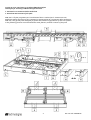
DRK-210 è il fly-bar progettato per l’installazione flown e stacked per il sistema VIO L210.
Nell’illustrazione seguente ne sono riportate le caratteristiche ed il contenuto della confezione.
DRK-210 is the fly-bar frame designed for flown and stacked configurations of VIO L210 systems.
In the following pictures are summarized the main features, and the contents of the pack.

3 Rev 1.0 cod. FOT000075
Una staffa inclusa nella confezione (con le relative viti necessarie al montaggio), permette l’eventuale utilizzo di un
inclinometro laser (opzionale), utile per determinare in maniera precisa l’angolazione del flybar in fase di
installazione e messa a punto dell’impianto.
One bracket (supplied in the pack together with all the screws needed for the mounting), allows the use of an optional
laser inclinometer, useful to estimate precisely the tilt angle of the flybar frame, in installing and tuning of the sound
system.

4 Rev 1.0 cod. FOT000075
2- Utilizzo del software di riferimento: dBTechnologies Composer
2-
Reference software use: dBTechnologies Composer
Il software di riferimento per il sistema VIO, è dBTechnologies Composer. Questo software fornisce un valido
supporto alla configurazione di sistemi audio indoor ed outdoor, ed in particolare è il software necessario ad
ogni calcolo strutturale relativo all’utilizzo di DRK-210. Il software è gratuito ed è scaricabile liberamente dal sito:
www.dbtechnologies.com nella sezione DOWNLOADS. Consigliamo di avvalersi da subito di questo indispensabile
strumento, insieme a queste istruzioni.
The reference software to design VIO sytems, is dBTechnologies Composer. It helps in any indoor or outdoor
configuration needs, and it is necessary for every DRK-210 safety calculations in its use. It is downloadable for free,
check it on www.dbtechnologies.com in DOWNLOADS section. We strongly recommend to start to use it
immediately within these instructions.
3- Importanti informazioni di sicurezza
3-
Important safety notice
DRK-210 deve essere utilizzato solo da personale esperto! Assicurarsi che l’installazione sia posizionata in
modo stabile e sicuro per scongiurare ogni condizione di pericolo per persone, animali e/o cose.
L’utilizzatore è tenuto a seguire le regolamentazioni e le leggi cogenti in materia di sicurezza nel Paese in cui si
utilizza il prodotto. Per l’utilizzo in sicurezza dell’accessorio, verificare periodicamente la funzionalità di tutte le
sue parti e l’integrità prima dell’utilizzo. La progettazione, i calcoli, l’installazione, il collaudo e la manutenzione
di sistemi sospesi o stack audio professionali deve essere effettuata esclusivamente da personale autorizzato. AEB
Industriale non è responsabile per installazioni improprie, in assenza dei requisiti di sicurezza.
DRK-210 must be installed by specialized personnel only! Make sure that the installation is positioned in a
stable and safe way in order to avoid any dangerous conditions for people, animals and/or objects. It is
mandatory to follow the safety law and regulations of the Country in which the equipment is installed.
Check periodically the integrity and functionality of all the parts of this optional equipment before the use, for a
safety installation. Design, calculation, installation, testing and maintainance of suspended and stacked
professional sound systems must be performed by qualified and authorized personnel only. AEB Industriale s.r.l.
denies any and all responsibility for improper installations, in the absence of safety requirements.

5 Rev 1.0 cod. FOT000075
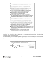
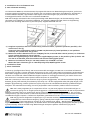
4- Installazione di un inclinometro laser
4-
Laser clinometer mounting
L’inclinazione di DRK-210, calcolata durante il progetto del sistema con dBTechnologies Composer, può essere
misurata tramite inclinometro laser (non fornito), per una maggiore precisione di installazione. Ad esempio, il
modello TEQSAS LAP-TEQ, rappresentato nelle figure successive. Vengono qui presentate le istruzioni di
montaggio della staffa a corredo con la confezione di DRK-210:
DRK-210 tilt-angle, calculated in the sound system design with dBTechnologies, can be measured by a laser
clinometer (not supplied), for a precise installation. For example, TEQSAS LAP-TEQ, shown in the following
pictures. The mounting instructions of the laser plate, supplied with DRK-210 are:
a) Scegliere la posizione del laser su DRK-210 (2 posizioni frontali, 2 posizioni posteriori possibili). I fori
relativi sono i fori [J].
Choose the laser-inclinometer position on DRK-210 placement (2 frontal positions, 2 rear positions
allowed). The related holes are [J] holes.
b) Montare la staffa in dotazione con le 2 viti M5X25 fornite, a seconda della scelta al punto a). Le viti devono
essere avvitate dall’esterno verso l’interno.
Mount the supplied plate for laser with the 2 supplied M5x25 screws, in the position of the a) choice. The
user has to screw them from the outside to the internal side of flybar frame.
c) Montare l’inclinometro laser (es. LAP-TEQ) tramite le 4 viti M4x8 a corredo.
Mount the laser clinometer (for ex. LAP-TEQ) using the 4 M4X8 supplied screws.
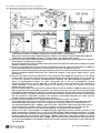
5- Installazione flown
5- Flown installation
In line-array (configurazione flown), VIO L210 necessita del montaggio con DRK-210. La massima inclinazione
ammessa fra il fly-bar e il primo elemento del line-array è di 4°. Tutti i dati relativi a inclinazione, posizionamento
delle staffe di aggancio motore [F], numeri di elementi del line-array ed ogni altra impostazione devono essere
calcolati con l’ausilio del software dBTechnologies Composer. Il montaggio meccanico, per motivi di sicurezza
deve avvenire in condizione statica (senza l’utilizzo di motori in movimento).
DRK-210 is necessary to mount VIO L210 line arrays in flown confifguration. The maximum admitted splay angle
between fly-bar frame and the first element of line-array is 4°. All the configuration data, like splay angles, load
adaptors [F] positioning, number of elements of line array must be calculated with the help of dBTechnologies
Composer. The mechanical mounting, has to be performed in static conditions, without motors movement.
DRK-210 è stato progettato per la sospensione di fino a 25 VIO L210 (oppure di 16 moduli Sub) per un
massimo di 750 kg con un singolo punto di aggancio. I componenti di sospensione di VIO L210 permettono
di connettere fino a 10 moduli (max 300 kg) senza limiti sull’angolazione del line array. Per ogni altra
configurazione, ogni informazione su dati come la portata massima e i punti di aggancio deve essere verificata
con dBTechnologies Composer. Il software è disponibile gratuitamente sul sito www.dbtechnologies.com.
DRK-210 fly frame is designed to suspend up to 25 x VIOL210 modules (or 16 x Sub modules) which
correspond to a total maximum weight of 750 kg (2000 lbs) with single hook connection. The rigging
components of VIO L210 allow to connect up to 10 modules (max 300 kg – 804 lbs) without any vertical
angle’s limit. For any other configuration, all the data about max load capability of VIO System and pick up point
of main/s hook/s, must be checked using dBTechnologies Composer software. Download it for free on
www.dbtechnologies.com.

6 Rev 1.0 cod. FOT000075
La procedura di installazione flown è la seguente:
The mounting instructions in flown configuration are:
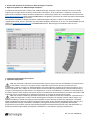
a) Progettare il sistema con dBTechnologies Composer. Riguardo l’installazione con DRK-210,
confrontare la sezione LAs PREDICT (schermate “System Data” e “Safety Data”).
Design the sound system with dBTechnologies Composer. For the most relevant data about DRK-210
installation, check LAs PREDICT section, in “System Data” and “Safety Data” pages.
b) Estrarre le staffe frontali del modulo VIO L210. Bloccarle in posizione fissa con gli appositi pin superiori
dello speaker come mostrato in figura.
Pull-up the brackets on the front side of VIO L210. Fasten them with the related quick-release pins of the
speaker as shown in the picture.
c) Estrarre i pin L da DRK-210. Inserire le staffe frontali del modulo VIO L210 nelle sedi relative su DRK-210,
in corrispondenza dei fori di questi pin. Fissare infine con i pin L lo speaker al fly-bar.
Extract the L quick-release pins from DRK-210 fly bar frame. Insert the front brackets of VIO L210 in the
houses of DRK-210 related with these pins. Fasten the speaker to the fly-bar frame using L quick-
release pins.
d) Estrarre il pin della sezione D e abbassare la staffa posteriore H sul DRK-210. Avvicinare il retro di VIO
L210 al fly-bar ed inserire la staffa H all’interno dell’alloggiamento posteriore di VIO L210. E’ necessario
un solo pin, inserito nell’angolo precedentemente calcolato con dBTechnologies Composer, per
fissare la configurazione flown sul retro. Assicurarsi che il pin sia correttamente inserito
all’interno della staffa, e sia ben bloccato. Il secondo pin può essere mantenuto nella posizione di
riposo “PIN HOLD”. Il massimo angolo ammesso, per motivi di sicurezza, tra il fly-bar ed il primo
modulo del line-array è 4°.
Extract the quick-release pin of D section and pull-down the H rear bracket in DRK-210. Move the rear
side of VIO L210 close to the DRK-210 fly-bar. It is necessary only one pin, inserted in the splay angle
calculated by dBTechnologies Composer, to fasten each module in the rear side in flown configuration.
Check that the pin is correctly inserted into the bracket and which is fastened correctly. The second pin
can be inserted in “PIN HOLD” position. The maximum splay angle admitted, for safety reasons,
between the first module and DRK-210 fly-bar frame is 4°.
e) Installare sul fly-bar DRK-210 1 o 2 giunti motori F (a seconda del numero di motori
nell’installazione flown del line-array). Nel caso di un solo giunto, dBTechnologies Composer nella
schermata Safety Data indica i 2 fori A in cui agganciare coi pin B il giunto F. E’ indicato anche il
verso di posizionamento di F: “FRONT” indica che il lato * del giunto F deve essere orientato verso il
fronte del line-array, “REAR” che deve essere orientato verso il retro del line-array. Nel caso di 2
giunti, il software indica i fori estremi di montaggio A, e l’orientamento è ininfluente.
Install one or two F load adaptors on DRK-210 fly-bar (depending on the number of motors in the
flown configuration of line-array). In case of one load adaptor, dBTechnologies Composer, in Safety
Data screen, show the number of 2 holes (A) in which F load adaptor has to be fastened by quick-release
pins B. It shows also the position reference of F: “FRONT” shows that * side of load adaptor F must be
oriented towards the front of line-array, “REAR” that it must be oriented toward the rear of line-array.
In case of 2 load adaptors, the software shows the extreme positions of the holes A, the orientation is
not important.

7 Rev 1.0 cod. FOT000075
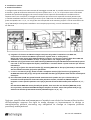
6- Installazione stacked
6- Stacked installation
In configurazione stacked, VIO L210 necessita del montaggio con DRK-210. E’ possibile montare un array di massimo
4 elementi. I gradi di inclinazione ammessi fra fly-bar e speaker sono: -3°, 0°, +3°. Il fly-bar deve avere inclinazione
parallela alla superficie d’appoggio. Può essere montato sul lato superiore di VIO S318 per l’installazione di un
impianto sonoro. Per il trasporto, il fissaggio del solo fly-bar può avvenire sul coperchio di un dolly DT-VIO L210.
In stacked installation DRK-210 is necessary to mount up to 4 VIO L210. The admitted splay angles between fly-bar
frame and speakers are: -3°, 0°, +3°. The fly-bar has to be parallel to the mounting surface. It can be mounted on the
top of VIO S318 for sound systems installation. For transport purpose only, It can be mounted on the cover of
DT-VIO L210.
a) Progettare il sistema con dBTechnologies Composer. Riguardo l’installazione con DRK-210,
confrontare la sezione LAs PREDICT (schermate “System Data” e “Safety Data”).
Design the sound system with dBTechnologies Composer. For the most relevant data about DRK-210
installation, check LAs PREDICT section, in “System Data” and “Safety Data” pages.
b)
Utilizzare i pin [L] per fissare con le staffe interne [K] DRK-210 sul top di VIO S318 o di DT-VIO L210 (in questo
caso solo ai fini del trasporto del fly-bar)
.
Confrontare i manuali relativi a questi accessori per ulteriori
informazioni.
Use pins [L] to fasten the internal brackets [K], mounting DRK-210 on the top of VIO S318, or DT-VIO L210.
See the related instructions for further information.
c) Su DRK-210
estrarre il pin [C]. Alzare le staffe a scomparsa anteriori [H] e fissarle con gli appositi pin.
On DRK-210 extract the pin [C]. Pull-up the retractable brackets [H] and fasten them with the related quick-
relase pins.
d)
Porre VIO L210 su DRK-210, prima fissando anteriormente lo speaker con i pin a rilascio veloce, poi
inserendo la staffa posteriore di VIO L210 nella posizione corretta, calcolata con dBTechnologies
Composer. Fissare quindi la posizione con il pin [C] inserito all’interno della staffa (valori ammessi +3°, 0°, -
3°).
Put VIO L210 on DRK-210. Fasten frontally the speaker, then insert the rear bracket of DRK-210, in the
correct position, calculated with dBTechnologies Composer as shown. Fasten that position with pin [C],
with the rear bracket of VIO L210 inserted in (admitted angles: +3°, 0°, -3°).
Features, specification and appearance of products are subject to change without notice.
dBTechnologies reserves the right to make changes or improvements in design or
manufacturing without assuming any obligation to change or improve products
previously manufactured.
-
 1
1
-
 2
2
-
 3
3
-
 4
4
-
 5
5
-
 6
6
-
 7
7


dBTechnologies DRK-210 Manuale del proprietario
- Tipo
- Manuale del proprietario
in altre lingue
Documenti correlati
-
dBTechnologies WB-VIOX15H Manuale del proprietario
-
-
-
 dB VIO S118 Manuale utente
-
-
-
-
-
-
