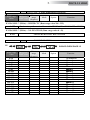
DTS DELTA 12 HEAD Manuale utente
- Categoria
- Proiettori
- Tipo
- Manuale utente

GB
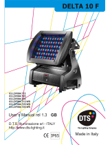
DELTA 12 HEAD
User’s Manual rel 1.1
D.T.S. Illuminazione srl - ITALY
http://www.dts-lighting.it
Made in Italy

2
DELTA 12 HEAD
Le informazioni contenute in questo documento sono state attentamente redatte e controllate. Tuttavia
non è assunta alcuna responsabilità per eventuali inesattezze. Tutti i diritti sono riservati e questo
documento non può essere copiato, fotocopiato, riprodotto per intero o in parte senza previo consenso
scritto della D.T.S .
DTS si riserva il diritto di apportare senza preavviso cambiamenti e modifiche estetiche , funzionali o di
design a ciascun proprio prodotto. D.T.S non assume alcuna responsabilità sull’uso o sull’applicazione
dei prodotti o dei circuiti descritti.
The information contained in this publication has been carefully prepared and checked. However, no
responsibility will be taken for any errors. All rights are reserved and this document cannot be copied,
photocopied or reproduced, in part or completely, without prior written consent from D.T.S.
D.T.S. reserves the right to make any aesthetic, functional or design modifications to any of its products
without prior notice. D.T.S. assumes no responsibility for the use or application of the products or circuits
described herein.
Les informations contenues dans le présent manuel ont été rédigées et contrôlées avec le plus grand
soin. Nous déclinons toutefois toute responsabilité en cas d'éventuelles inexactitudes. Tous droits
réservés. Ce document ne peut être copié, photocopié ou reproduit, dans sa totalité ou partiellement,
sans le consentement préalable de .
se réserve le droit d'apporter toutes modifications et améliorations esthétiques, fonctionnelles ou
de design, sans préavis, à chacun de ses produits. décline toute responsabilité sur l'utilisation ou
sur l'application des produits ou des circuits décrits.
D.T.S
D.T.S.
D.T.S.
Las informaciones contenidas en este documento han sido cuidadosamenteredactadas y
controladas. Con todo, no se asume ninguna responsabilidad por eventuales inexactitudes.
Todos los derechos han sido reservados y este documento no puede ser copiado, fotocopiado
o reproducido, total o parcialmente, sin previa autorizaciónescrita de
se reserva el derecho a aportar sin previo aviso cambios y modificaciones de carácter
estético, funcional o de diseño a cada producto suyo. no se asume responsabilidad de
ningún tipo sobre la utilización o sobre la aplicació
n de los productos o de los circuitos descritos.
D.T.S.
D.T.S.
D.T.S.

3
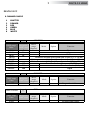
INDEX:
1- SYMBOLS 4
2- GENERAL WARNING 4
3- GENERAL WARRANTY CONDITION 4
4- TECHNICAL FEATURES 5
5- ACCESSORIES 7
6- IMPORTANT SAFETY INFORMATION 8
6.1 Fire prevention
6.2 Prevention of electric shock
6.3 Protection against direct light radiation
6.4 Safety
6.5 Level of protection against the penetration of solid and liquid matter
6.6 Waste Electrical and Electronic Equipment directive
7- VOLTAGE AND FREQUENCY 8
8- INSTALLATION 9
8.1 Safety cable
8.2 Protection against liquid
8.3 Movement
8.4 Risk of fire
8.5 Forced ventilation
8.6 Ambient temperature
9- MAINS CONNECTION 11
9.1 Protection:
10- DMX SIGNAL CONNECTION 12
10.1 DMX Addresses
10.2 Selecting the DMX address
11- FIRMWARE UPDATING 13
12- ACCESS TO DISPLAY CARD 13
13- DISPLAY FUNCTIONS 14
14- AUTOMATIC OPERATION 19
14.1 CUPr-RAIn-CU01/CU16-Wh01/Wh16
14.2 ChPr MASTER/SLAVE
14.3 Rec mode
15- PERIODIC CLEANING 21
16- PERIODIC CONTROLS 21
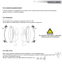
17- REPLACING THE LENSES 22
18- DMX PROTOCOL 24
19- AMPHENOL CABLE CONNECTOR WIRING CONNECTIONS 46
DELTA 12 HEAD

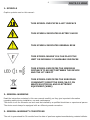
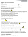
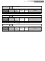
1- SYMBOLS
Graphic symbols used on this manual:
2- GENERAL WARNING
Read the instruction contained in this user manual carefully, as they give important information
regarding safety during installation, use and maintenance.
The device is not for domestic use and must be installed by a qualified electrician or experienced person.
The device must always be equipped with an efficient ground connection.
3- GENERAL WARRANTY CONDITIONS
The unit is guaranteed for 36 months from the date of purchase against manufacturing material defects.
THIS SYMBOL INDICATES A HOT SURFACE
THIS SYMBOL INDICATES ELECTRIC SHOCK
THIS SYMBOL INDICATES GENERAL RISK
THIS SYMBOL MEANS YOU CAN PLACE THE
UNIT ON NORMALLY FLAMMABLE SURFACES
!
THIS SYMBOL INDICATES THE MINIMUM
DISTANCE TO BE KEPT BETWEEN THE DEVICE
AND THE LIT OBJECT
4
DELTA 12 HEAD
THIS SYMBOL INDICATES THE EUROPEAN
COMMUNITY DIRECTIVE 2002/96/EC ON
WASTE ELECTRICAL AND ELECTRONIC
EQUIPMENT (WEEE)

5
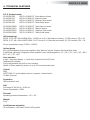
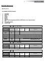
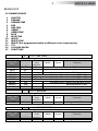
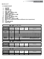
4- TECHNICAL FEATURES
D.T.S. Product codes:
03.LDF008.F08 DELTA 12 HEAD FC *Ultra-Narrow lenses
03.LDF008.F12 DELTA 12 HEAD FC *Narrow lenses
03.LDF008.F25 DELTA 12 HEAD FC *Medium flood lenses
03.LDF008.F45 DELTA 12 HEAD FC *Wide flood lenses
03.LDF008.FW08 DELTA 12 HEAD CT *Ultra-Narrow lenses
03.LDF008.FW12 DELTA 12 HEAD CT *Narrow lenses
03.LDF008.FW25 DELTA 12 HEAD CT *Medium flood lenses
03.LDF008.FW45 DELTA 12 HEAD CT *Wide flood lenses
LED technology
DELTA 12 FC: 48 x FULL RGBW LEDs; 22.050 Lux at 5 m (Ultra-Narrow lenses); 17.728 Lumens; CRI > 90
DELTA 12 CT: 48 x FULL WHITE LEDs; 31.972 Lux at 5 m (Ultra-Narrow lenses); 25.700 Lumens; CRI > 90
Colour temperature range: 2700°K - 6500°K
Optical group
Four interchangeable lenses sets available: Ultra-Narrow; Narrow; Medium flood and Wide flood
8 additional (optional) holographic filters available (user interchangeable): 10° / 20° / 30° / 40° / 60° / 80° /
60° x 10° / 75° x 45°
User interface
4 digit 7 segments display + 4 soft keys (located into the PSU box)
Independent operation
Fully programmable via built-in user interface
Master or Slave capability (chains of up to 32 interconnected units)
Control
RDM
USITT DMX 512 serial digital protocol (reception / transmission)
10 DMX channels
Protection
IP65 protection level
PSU
Full-range AC 90-260 V / 50-60 Hz
Power consumption: 500W
Thermal
Operating ambient temperature: -10° / 40°
Weight
9 Kg
Certifications and safety
CE certification; LED class: Class 2 LED product
DELTA 12 HEAD

6
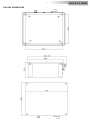
PSU BOX DIMENSIONS
DELTA 12 HEAD

7
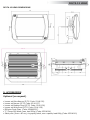
DELTA 12 HEAD DIMENSIONS
5- ACCESSORIES
Optional (on request)
• Lenses set Ultra-Narrow (D.T.S. Code: 03.LK.130)
• Lenses set Narrow (D.T.S. Code: 03.LK.127)
• Lenses set Medium flood (D.T.S. Code: 03.LK.128)
• Lenses set Wide flood (D.T.S. Code: 03.LK.129)
• Diffusion Frost Glass (Code: 0506V022.F)
• “C” Clamp G60 black (max. load 50Kg) (Code: 0521A004)
• Safety wire (3mm x 60 cm), ring spring catch, max. capacity load 60Kg (Code: 0521A010)
DELTA 12 HEAD

!
!
8
6- IMPORTANT SAFETY INFORMATION
6.1 Fire prevention:
-It is permissible to place the unit on normally flammable surfaces.
Suitable for mounting on normally flammable materials surfaces greater than 200°C with some
combustion time lag.
-Minimum distance from the closest illuminable surface: 1 m.
-Replace any blown or damaged fuses only with those of identical value (6,3A T).
Refer to the wiring diagrams if there is any doubt.
-Connect the PSU to mains power via a thermal magnetic circuit breaker.
6.2 Prevention of electric shock:
-High voltage is present inside the PSU. Isolate the PSU from the mains supply prior to performing any
function which involves touching the inside of the box.
-The level of technology inherent in the DELTA 12 HEAD requires the assistance of specialised personnel
for all servicing. Please refer to an authorised D.T.S. service centre.
-A good earth connection is essential for proper functioning of the projector.
Never connect the unit without proper earth connection.
-The fixture should be located in places with a good air ventilation.
6.3 Protection against direct light radiation:
-Never turn the unit on if any of the lenses or the glass lenses protection is damaged.
-Never look directly the LEDs when they are on.
6.4 Safety:
-The projector should always be installed with bolts, clamps and other tools that are capable of
supporting the weight of the unit.
-Always use a second safety chain to sustain the weight of the unit in case of the failure of the main
fixing point.
-The external surface of the unit, at various points, may exceed 80°C.
Never handle the unit until it’s on.
-Never install the fixture in an enclosed area lacking sufficient air flow.
-The ambient temperature should not exceed 40°C.
6.5 Level of protection against the penetration of solid and liquid matter:
-The projector and the PSU are classified as an outdoor appliances and their protection level against the
penetration of solid and liquid matter is IP 65.
6.6 Waste Electrical and Electronic Equipment (WEEE) directive:
The machine, accessories and packaging should be sorted for environmental-friendly recycling.
For EC countries: according to the European Directive 2002/96/EC for Waste Electrical and Electronic
Equipment and its implementation into national right, luminaires that are no longer usable must be
collected separately and disposed of in an environmentally correct manner.
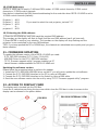
7- VOLTAGE AND FREQUENCY:
DELTA 12 HEAD with PSU can operates at 90-260V AC , 50 or 60 Hz.
DELTA 12 HEAD

9
DELTA 12 HEAD may be ceiling mounted.
We recommend the use of appropriate clamps to fix the unit to the mounting surface.
The supporting structure from which the unit is hung should be capable of bearing the weight of the unit,
as should any clamps used to hang it.
Fixing clamps for truss are not included into the unit box.
8- INSTALLATION
8.1 Safety cable:
We recommend the use of a safety cable or chain connected to the DELTA 12 HEAD and to the
suspension truss in order to avoid the fixture accidentally falling should the main fixing point fail.
Make sure that the iron cable or chain can bear the weight of the entire unit.
!
DELTA 12 HEAD

8.2- Protection against liquids
If IP 65 protection is impaired for any reason, do not expose this product to external atmospheric
agents, because it could be damaged.
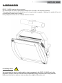
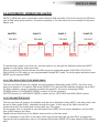
8.3- Movement
The projector has a maximum movement of 90° for Tilt.
Do not place any obstructions in the path of the projector's movement.
8.4- Risk of fire
Each fixture produces heat and must be installed in a well-ventilated place.
It is permissible to place the unit on normally flammable materials surfaces greater than 200°C
with some combustion time lag.
Minimum distance from the object being illuminated is 1 m.
WARNING
Do not place any object in the path
of the projector’s movement
!
90°
10
DELTA 12 HEAD
90°

11
8.5- Forced ventilation
You can reduce the noise level, if needed, by setting the internal fans to minimum speed or completely
eliminate the noise by turning the fans Off (see page 16). The projector always works safely, thanks
to a built-in thermal protection that automatically dims LED power in case the temperature of the LED
Panel exceeds 70°C .
8.6- Ambient temperature
The projector should never be installed in places that lack a constant air flow.
The ambient temperature should not exceed 40°C.
Prior to connecting the PSU to your mains supply, ensure that the model in your possession correctly
matches the mains supply available.
9- MAINS CONNECTION:
DELTA 12 HEAD with PSU can operates at 90-260 V AC / 50 or 60 Hz.
For connection purposes, ensure that your plug can support 6 amps at 110V and 3 amps at 230V each
unit connected.
Strict adherence to regulatory norms is strongly recommended.
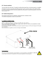
9.1 Protection:
The use of a thermal magnetic circuit breaker is recommended for each DELTA 12 HEAD PSU.
A good earth connection is essential for the correct operation of the projector.
!
FUSE
6,3A T
MAINS AC INPUT
90-260V 50/60 Hz
DMX IN
PSU BOX
GORE
VALVE
LED OUT
To DELTA 12 HEAD
DMX OUT
DELTA 12 HEAD

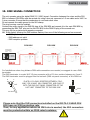
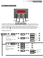
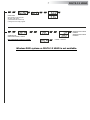
10- DMX SIGNAL CONNECTION
The unit operates using the digital DMX 512 (1990) signal. Connection between the mixer and the PSU
BOX or between PSU BOXs must be carried out using a two pair screened ø 0.5 mm cable and a XLR 5 or
3 pins connector. Ensure that the conductors do not touch each other.
Do not connect the cable ground to the XLR chassy.
The plug housing must be isolated.
Connect the mixer signal to the DMX IN plug of the PSU BOX and connect it to the next PSU BOX by
connecting the DMX OUT plug on the first PSU BOX to the DMX IN plug of the second one.
This way, all the projectors are cascade connected.
NB. If the display showing the DMX address flashes, then one of the following errors has occurred:
- DMX signal not present
- DMX address not valid
- DMX reception problem
For Installations where long distance DMX cable connections are needed, we suggest to use a DMX
terminator.
The DMX terminator is a male XLR 3-5 pins connector with a 120 ohm resistor between pin 2 and 3.
The DMX terminator must be plugged into the last unit (DMX out panel connector) of the DMX line.
1
2
3
5
4
OUT
120 ohm
PIN 3
PIN 2
PLACE A 120 OHM RESISTOR BETWEEN PIN 2
AND 3 OF A MALE XRL CONNECTOR AND PLUG IT
INTO THE DMX OUT PANEL CONNECTOR OF THE
LAST UNIT CONNECTED TO THE DMX LINE
12
Please note that the XLR connectors installed on the DELTA 12 HEAD PSU
BOX have an IP20 protection rate.
Thus, for any application where an IP65 rate is needed, the XLR connectors
must be protected within an IP65-rated container.
!
5
3
4 2
1
1=GND
2=DATA-
3=DATA+
CONTROLLER
S T A N D A R D
D M X 5 1 2
DMX OUTDMX OUT
DMX OUTDMX OUT
DMX IN
DMX INDMX IN DMX INDMX IN
DMX OUTDMX OUT
DMX INDMX IN
DMX OUTDMX OUT
PSU BOX PSU BOX PSU BOX
DELTA 12 HEAD

10.1 DMX Addresses:
DELTA 12 HEAD can be used in 3 different DMX modes: 10 DMX control channels, 6 DMX control
channels or 15 DMX control channels.
Here below is described the DMX channels addressing for the controller when DELTA 12 HEAD is set to
10 DMX control channels (default):
Projector 1 A001
Projector 2 A011 If you want to select the next projector, just add “10”
Projector 3 A021
….. A….
projector 6 A051
10.2 Selecting the DMX address:
1) Press the UP-DOWN key until you reach the required DMX address.
The numbers on the display will start to flash (but the new DMX address hasn't yet been set).
2) Press ENTER to confirm your selection. The numbers on the display will stop flashing and the
projector is now controlled by the new DMX address.
TIPS: if you keep pushed the UP or DOWN keys, the channels are calculated more quickly and you get a
faster selection.
- “D.T.S. Firmware upgrade utility” program installed on PC
- Latest firmware release available for DELTA 12 HEAD unit
D.T.S. Firmware upgrade utility”
11- FIRMWARE UPDATING
To update the software version of the DELTA 12 HEAD you need:
- D.T.S. RED BOX interface (D.T.S. Code: 03.LA.008)
- USB-DMX Driver for the D.T.S. RED BOX interface
Updating the software version.
Please follow the procedure below to perform the update:
1. Install the D.T.S. RED BOX USB-DMX driver on the PC you will use to update the unit software.
2. Connect the D.T.S. RED BOX interface to the PC by using a USB cable.
3. Connect the D.T.S. RED BOX interface to the fixture by using a DMX cable.
4. Send the new software version into the unit by using “ program.
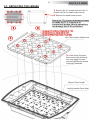
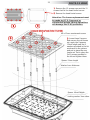
12- ACCESS TO DISPLAY CARD
The display card is located into the PSU Box.
Loose the 4 marked screws fixing the top cover which close the PSU box in order to access to the
display card as showed in the picture below.
13
DISPLAY
CARD
DISPLAY
CARD
PSU BOX INTERNAL VIEW
PSU BOX
DELTA 12 HEAD

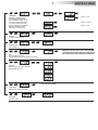
13- DISPLAY FUNCTIONS
DOWN
UP
ENTER
MENU
14
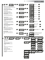
DISPLAY FUNCTIONS
The DELTA 12 HEAD display panel shows all the available functions. Using these functions, it is
possible to change some of the parameters and add some functions. Changing the D.T.S. setting
can vary the functions of the unit so that it does not respond to the DMX 512 signal used to
control it. Carefully follow the instructions below before carrying out any variations or selections.
NOTE: the symbol shows which key has to be pushed to obtain the desired function.
Up-DownMENU ENTER
DMX MODE
To select DMX mode: 10 ch (Default), 6
ch, 15 ch and MACRO mode
6 CHANNELS
Up-Down
Up-Down
ENTER
Up-Down
MENU
ENTERUp-Down
REVERSE DISPLAY
Reverses display's reading depending on
the mounting position (on the ground or
suspended).
Up-Down
Floor
position
Suspension
position
Up-DownENTER
Up-DownENTER
DISPLAY STAND BY
To turn off the display (after 5 seconds)
Or leave it always on.
Display OFF
Display
always ON
ENTER
ENTER
ENTER
ENTER
Default
10 CHANNELS
Up-Down
Up-Down
MACRO
MACRO Function, enable channel
mapping macro rainbow effects
STD (default)
Up-DownENTER
ENTER
ENTER
No rainbow macros
(Default)
Rainbow macros
activated
15 CHANNELS
ENTER
ENTER
DELTA 12 HEAD
Software version 2.25

Up-Down
MENU
ENTERUp-Down
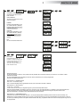
LED
RGBA Min/Max, Smooth, Compression,
Sync level values settings and Boost mode
Up-Down
Up-DownENTER
Up-DownENTER
ENTER
ENTER
ENTER
ENTER
Up-Down
Up-DownENTER
ENTER
ENTER
RGBA MINIMUM VALUES
This menu allows to select the
minimum levels for Red, Green,
Blue and White
RGBA MAXIMUM VALUES
This menu allows to select the
maximum levels for Red, Green,
Blue and White
Default = 100
Default = 0
Default = 0
Default = 0
Default = 100
Default = 100
These settings have priority on
Master Dimmer (DMX channel 2)
Up-Down
Up-DownENTER
ENTER
Range = Off - 20
Default = 4
SMOOTH VALUE
This menu allows to select the
value of the delay (in milliseconds)
for RGBW and Dimmer channels
reaction to DMX or Program
variation.
Off = 25 ms delay (Fast response)
20 = 250 ms delay (Slow response)
Up-Down
Up-DownENTER
ENTER
Linear = Linear
current output
COMPRESSION
This menu allows to select between
Linear current output or Quadratic
current output for LEDs
Default = Linear
Quadratic =
Linear light
output
ENTER
Up-DownENTER
ENTER
ENTER
Default = 0
Default = 100
SYNC
This menu allows to adjust the
PWM frequency value (Hz) in order
to reduce flickering in the process
of your camera recordings
Up-Down
Up-DownENTER
Range = 610 Hz -10 KHz
Default = 610 Hz
ENTER
15
Up-DownENTER
BOOST DRIVING
This menu allows to increase the
LED’s current from 350 mA to 500
mA
Up-Down
With BOOST active, the LED’s
current is setted to 500 mA
(30% more gain).
Default = Enabled
Up-Down
AUTOMATIC MODE
Automatic demo game without
DMX controller
Up-DownENTER
ENTER
MENU
Up-Down
ENTER
ENTER
Up-Down
CUPr
RGBW values selectable by user
CU01-CU16
Color Macros as on DMX channel
8 (Macro)
ENTER
Up-Down
ENTER
ChPr
Chase with 16 steps previously
created in REC MODE
Speed and Wait time selectable
by user
ENTER
Rainbow (rAIn)
Rainbow colours effect.
Speed time selectable by user
ENTER
Up-Down
Up-DownENTER ENTER
Up-Down
DELTA 12 HEAD

16
AUTOMATIC MODE
Automatic demo game without
DMX controller
Up-DownENTER
ENTER
MENU
Up-Down
Up-DownENTER ENTER
WHITE MACROS
16 macros for White colour from
2700°K to 6500°K
Up-DownENTER
Up-DownENTER
ENTER
ENTER
DIMMER
Dimmer level selectable by user
as on DMX channel 2 (Dimmer)
Dimmer level is active for all the
programs and macros
SHUTTER
Shutter level selectable by user
as on DMX channel 1 (Shutter)
Shutter level is active only for
CU01/CU16 and Wh01/Wh16
macros
ESC
Esc from Automatic Mode Menu
ENTER
ENTER
MENU
Up-Down
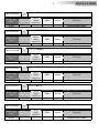
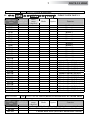
DMX Recorder Mode
For the programming of ChPr by using a DMX controller, besides the 10 channels necessary to control the unit a further 3 DMX
channels are needed.
So that in RECORDER mode (via DMX) the unit will need 13 channels to be correctly programmed.
The three new DMX channels are:
DMX channel 11 = SCENES channel
From 0-10 = no function (r001)
From 11-255 are displayed the programmable scenes (max 16 scenes from M001 to M0016)
DMX channel 12 = EDIT channel:
-From 0-19 = no function
-From 20-234 the unit runs the configuration given by the received input DMX values.
With the channel SCENES it is possible to pass from one step to the next while with REC it is possible to record the selected scene.
-From 235-255 the unit runs the configuration given by the received input DMX values closing the sequence as last scene.
With the channel REC it is possible to record the selected scene as last scene.
DMX channel 13 = RECORDING channel
Records the set scene with a variation between 0 to 255 (the display flashes indicating that the scene has been recorded). It is
advised that you keep the REC channel set to 0 and to run through the 255 only once you have decided to save the scene. If ChPr is
not closed, by indicating the last scene (Edit channel between 235-255), in playback mode all 16 scenes will be played through even if
not programmed.
REC MODE
In DMX Recorder Mode, it is
possible to create and store the
scenes of the ChPr by using an
external DMX controller.
The unit must be setted to 10
DMX channels mode
DELTA 12 HEAD

17
Up-DownENTER
ENTER
MENU
Up-Down
ENTER
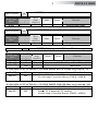
SLAVE MODE
Slave mode for ChPr program.
All slave units will be
synchronised with master unit,
running their own Chpr program.
Up-DownENTER
MENU
Up-Down
WIRELESS DMX
Wieless DMX enabled / disabled.
Not implemented on DELTA 12 HEAD.
Up-DownENTER
ENTER
ENTER
UNLINK = LOG OUT
WIRELESS DMX SYSTEM
ENABLED
WIRELESS DMX SYSTEM
DISABLED
DELTA 12 HEAD
Wireless DMX system on DELTA 12 HEAD is not available.

ENTER
FAN
Fan max speed regulation
Off (fan always off) -12-14-16-18-20-22-24 Volt
Up-Down
MENU
Up-Down
MENU
Up-DownENTER
TEMPERATURE
Unit temperature
.
ENTERENTER
DEFAULT
To restore default settings
Up-Down
MENU
EMERGENCY
Emergency operating mode.
By setting Emergency mode, it
will be possible to select one of
the 16 pre-programmed WHITE
cues that will then ran if DMX
signal is missing or not available.
Usefull for Emergency EXIT
illumination on public areas.
Up-Down
MENU
Up-DownENTER
Up-DownENTER
ENTER
ENTER
Default = OFF
Default = White 1
Default = 255
ENTER
18
ENTER
Up-DownENTER
LIFE TIME
This menu show the total unit life time
and the RGBW life time
Up-Down
MENU
ENTER
Up-Down
MENU
ENTER
TEST MODE
RGBW colours test with rainbow
Up-Down
MENU
SOFTWARE
Software version
.
.
ENTER
ENTER
Not yet activated
FAN OFF or set from 12V to 24V = Unit thermally
protected with automatic LED power dimming in
case temperature of the LED panel exceed 70°C .
DELTA 12 HEAD

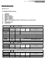
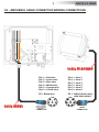
14-AUTOMATIC OPERATION (AUTO)
DELTA 12 HEAD can work in automatic mode without a DMX controller. First of all connect the PSU Boxs
with a DMX cable (picture below). A maximum quantity of 32 slave units can be connected to the same
Master unit.
To activate Auto mode on the first unit, use the menu to run through the different modes until AUTO
appears on the display, and press enter.
Now it is possible to choose between the different pre-programmed games (CUPr-RAIn-CU01/CU16-
Wh01/Wh16) or ChPr which is user programmable through REC mode. To confirm game activation press
ENTER on the selected GAME.
14.1 CUPr-RAIn-CU01/CU16-Wh01/Wh16
The first unit that will work as a Master should be placed in Automatic mode (AUTO), the other units
have to be placed in 10 channels DMX mode (MODE 10CH) and the DMX address should be set at A001.
For RaIn (rainbow) game it is possible to select the speed for the colour changhing (SPEE).
DIMMER function (in AUTOMATIC MODE) is active for all the programs.
SHUTTER function (in AUTOMATIC MODE) is active only for CU01/CU16 and Wh01/Wh16 macros.
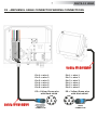
14.2 ChPr MASTER/SLAVE
The first unit that will function as a Master must be set to Automatic mode (AUTO), the other units must
be set to Slave mode (SLAV), selectable through the menu. In this way all the Slave units will be
synchronised with the master and running their own ChPr game.
On the master unit it is possible to vary the Speed time (SPEE) for the colour changhing and the Wait
time (UAIt) between the steps.
Speed time and Wait time on the Master, have priority on the slave units.
NB: It is possible to run GA.Pr on the other units even though these do not have GA.Pr programmed.
You can do this by setting the units to 10 channels DMX mode (MODE 10CH) and selecting DMX address
A001.
19
DELTA 12 HEAD
DMX OUTDMX OUT
DMX IN
DMX INDMX IN
DMX OUTDMX OUT
DMX INDMX IN
DMX OUTDMX OUT
SLAVE 1 SLAVE 2
DMX INDMX IN
SLAVE 32MASTER
PSU BOXPSU BOX PSU BOX PSU BOX

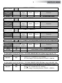
14.3 Rec mode
It is possible to program your own game on DELTA 12 HEAD that will then run it in AUTO mode (ChPr).
Each unit can have its own programmed game.
In REC mode the unit must be set to 10 DMX channels mode.
To program the ChPr by using a DMX controller, you need 3 more channels in addition to the 10 channels
necessary to control the unit.
So that in RECORDER mode (via DMX) the unit will need 13 DMX channels to be correctly programmed.
The three new DMX channels are:
DMX channel 11 = SCENES channel
From 0-10 = no function (r001)
From 11-255 are displayed the programmable scenes (max 16 scenes from M001 to M0016)
DMX channel 12 = EDIT channel:
-From 0-19 = no function
-From 20-234 the unit runs the configuration given by the received input DMX values.
With the channel SCENES it is possible to pass from one step to the next while with REC it is possible to
record the selected scene.
-From 235-255 the unit runs the configuration given by the received input DMX values closing the
sequence as last scene.
With the channel REC it is possible to record the selected scene as last scene.
DMX channel 13 = RECORDING channel
Records the set scene with a variation between 0 to 255 (the display flashes indicating that the scene
has been recorded). It is advised that you keep the REC channel set to 0 and to run through the 255 only
once you have decided to save the scene. If ChPr is not closed, by indicating the last scene (Edit channel
between 235-255), in playback mode all 16 scenes will be played through even if not programmed.
20
DELTA 12 HEAD
La pagina si sta caricando...
La pagina si sta caricando...
La pagina si sta caricando...
La pagina si sta caricando...
La pagina si sta caricando...
La pagina si sta caricando...
La pagina si sta caricando...
La pagina si sta caricando...
La pagina si sta caricando...
La pagina si sta caricando...
La pagina si sta caricando...
La pagina si sta caricando...
La pagina si sta caricando...
La pagina si sta caricando...
La pagina si sta caricando...
La pagina si sta caricando...
La pagina si sta caricando...
La pagina si sta caricando...
La pagina si sta caricando...
La pagina si sta caricando...
La pagina si sta caricando...
La pagina si sta caricando...
La pagina si sta caricando...
La pagina si sta caricando...
La pagina si sta caricando...
La pagina si sta caricando...
La pagina si sta caricando...
La pagina si sta caricando...
-
 1
1
-
 2
2
-
 3
3
-
 4
4
-
 5
5
-
 6
6
-
 7
7
-
 8
8
-
 9
9
-
 10
10
-
 11
11
-
 12
12
-
 13
13
-
 14
14
-
 15
15
-
 16
16
-
 17
17
-
 18
18
-
 19
19
-
 20
20
-
 21
21
-
 22
22
-
 23
23
-
 24
24
-
 25
25
-
 26
26
-
 27
27
-
 28
28
-
 29
29
-
 30
30
-
 31
31
-
 32
32
-
 33
33
-
 34
34
-
 35
35
-
 36
36
-
 37
37
-
 38
38
-
 39
39
-
 40
40
-
 41
41
-
 42
42
-
 43
43
-
 44
44
-
 45
45
-
 46
46
-
 47
47
-
 48
48


DTS DELTA 12 HEAD Manuale utente
- Categoria
- Proiettori
- Tipo
- Manuale utente
in altre lingue
- English: DTS DELTA 12 HEAD User manual
Documenti correlati
-
 DTS F-25 Manuale utente
-
 DTS SCENA LED 80 FR FC Manuale utente
-
 DTS Delta 8 Full Colour R Manuale utente
-
 DTS Brick Manuale utente
-
 DTS DRIVENET 1664 Manuale utente
-
 DTS TITAN PLUS SOLO Manuale utente
-
 DTS FOS 100 FULL RGBW Manuale utente
-
 DTS FOS 100 SOLO FULL WHITE CT Manuale utente
-
 DTS X-BRICK Manuale utente
-
 DTS SCENA LED 200 MZ FC Manuale utente


