Trox FAM-RADIODUCT Guida d'installazione
- Tipo
- Guida d'installazione

X-AIRCONTROL
FAM-RD
Installation and operating manual GB/en
Field Application Module
with RadioDuct expansion module

A00000092825, 1, GB/en
Translation of the original
TROX GmbH
Heinrich-Trox-Platz
47504 Neukirchen-Vluyn
Germany
Phone: +49 (0) 2845 2020
Fax: +49 (0) 2845 202-265
E-mail: [email protected]
Internet: http://www.troxtechnik.com
09/2022
X-AIRCONTROL FAM-RD2

1 Product overview....................................... 4
2 General information................................... 6
3 Safety.......................................................... 7
Correct use.................................................. 7
Dangers and risks........................................ 8
Qualified staff............................................... 8
4 Delivery and storage.................................. 9
Transport...................................................... 9
Storage ....................................................... 9
Packaging.................................................... 9
5 Parts and function..................................... 9
Functional description.................................. 9
6 Installation................................................ 11
General installation information.................. 11
Fixing the antenna mounting bracket......... 11
7 Electrical connection............................... 12
General information................................... 12
Wiring examples........................................ 12
8 Commissioning........................................ 14
General...................................................... 14
Activation................................................... 15
9 Diagnosis / troubleshooting................... 18
Diagnosis information in the configuration
software..................................................... 18
Diagnosis information on the main PCB.... 18
Diagnosis information on the RadioDuct
expansion module...................................... 19
10 Technical data.......................................... 20
Dimensions................................................ 20
11 Decommissioning.................................... 21
Safety......................................................... 21
Disassembly............................................... 21
Disposal..................................................... 21
12 Index........................................................ 0
Table of contents
X-AIRCONTROL FAM-RD 3

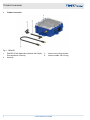
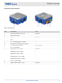
1 Product overview
Fig. 1: FAM-RD
1 FAM-RD (Field Application Module with Radio-
Duct expansion module)
2 Antenna
3 Antenna mounting bracket
4 Antenna cable, 50 cm long
Product overview
X-AIRCONTROL FAM-RD4

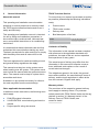
Connections and interfaces
Fig. 2: Connections
Item Description Note
1 Sensor connections S1, S2, S3 Not used
2 Antenna connection
3 CL1
CL2
Not used
4 T5 = X-AIRCONTROL connection
5 Push button for enabling service port T1
6 T1 = service and multi port
T2 -T4 = multi ports
T2-T4 not used
7 Digital input 1 (DI1 + GND)
Digital input 2 (DI2 + GND)
Digital input 3 (DI3 + GND)
Analogue input 1 (AI1 + GND)
Temperature input (TI1 + GND)
Not used
8 Power = power supply
9 Digital output DO (NO, C, NC) Not used
Product overview
X-AIRCONTROL FAM-RD 5

2 General information
About this manual
This operating and installation manual enables
operating or service personnel to correctly install
the TROX product described below and to use it
safely and efficiently.
This operating and installation manual is intended
for use by fitting and installation companies, in-
house technicians, technical staff, instructed per-
sons, and qualified electricians or air conditioning
technicians.
It is essential that these individuals read and fully
understand this manual before starting any work.
The basic prerequisite for safe working is to comply
with the safety notes and all instructions in this
manual.
The local regulations for health and safety at work
and general safety regulations also apply.
This manual must be given to the system owner
when handing over the system. The system owner
must include the manual with the system documen-
tation. The manual must be kept in a place that is
accessible at all times.
Illustrations in this manual are mainly for informa-
tion and may differ from the actual design.
Other applicable documentation
In addition to these instructions, the following docu-
ments apply:
FAM-RD product information
X-AIRCONTROL commissioning and service
manual
Project-specific wiring documents
TROX Technical Service
To ensure that your request is processed as quickly
as possible, please keep the following information
ready:
Product name
TROX order number
Delivery date
Brief description of the fault
Online www.troxtechnik.com
Phone +49 2845 202-400
Limitation of liability
The information in this manual has been compiled
with reference to the applicable standards and
guidelines, the state of the art, and our expertise
and experience of many years.
The actual scope of delivery may differ from the
information in this manual for bespoke construc-
tions, additional order options or as a result of
recent technical changes.
The obligations agreed in the order, the general
terms and conditions, the manufacturer's terms of
delivery, and the legal regulations in effect at the
time the contract is signed shall apply.
Warranty claims
The provisions of the respective general delivery
terms apply to warranty claims. For purchase
orders placed with TROX GmbH, these are the reg-
ulations in section "Vl. Warranty claims" of the
Delivery Terms of TROX GmbH, see
www.trox.de/en/.
General information
X-AIRCONTROL FAM-RD6

Copyright
This document, including all illustrations, is pro-
tected by copyright and pertains only to the corre-
sponding product.
Any use without our consent may be an infringe-
ment of copyright, and the violator will be held liable
for any damage.
This applies in particular to:
Publishing content
Copying content
Translating content
Microcopying content
Saving content to electronic systems and
editing it
Safety notes
Symbols are used in this manual to alert readers to
areas of potential hazard. Signal words express the
degree of the hazard.
Comply with all safety instructions and proceed
carefully to avoid accidents, injuries and damage to
property.
DANGER!
Imminently hazardous situation which, if not
avoided, will result in death or serious injury.
WARNING!
Potentially hazardous situation which, if not
avoided, may result in death or serious injury.
CAUTION!
Potentially hazardous situation which, if not
avoided, may result in minor or moderate injury.
NOTICE!
Potentially hazardous situation which, if not
avoided, may result in property damage.
ENVIRONMENT!
Environmental pollution hazard.
3 Safety
Correct use
FAM-RD is used as part of X-AIRCONTROL for
radio-based data transmission through ducting.
The data is transmitted in two directions between
zone module and zone master.
Safety
X-AIRCONTROL FAM-RD 7

Correct use requires that both the transmitter
module and the receiver module are placed in the
same duct system, i.e. either in the supply air duct
or in the extract air duct. FAM-RD must not be used
outdoors.
Residual risks
A power failure will interrupt data transmission. If a
system has to be highly reliable and available, you
should take backup measures to prevent problems
in case of a power failure.
Also, the radio communication between the various
nodes of an X-AIRCONTROL system can be inter-
rupted by interference. This, too, may lead to trans-
mission losses.
If a system has to be highly reliable and available, a
wired connection is the better option for data trans-
mission.
Incorrect use
Do not use the product for areas of application that
are not described in this manual.
Do not use the product:
outdoors
in wet areas
in areas with potentially explosive atmospheres
Dangers and risks
NOTICE!
Risk of damage to property due to large tem-
perature differences
If any electronic components have been kept in
an unheated area, condensation may form and
damage the electronic components beyond
repair.
– Before you start commissioning, make sure
that all devices have warmed up to the
ambient temperature. Only after about
2 hours will the system have reached
ambient temperature.
NOTICE!
Risk of damage to property due to foreign
matter and liquids!
Foreign matter and liquids that get into the unit
may damage the electronic parts.
– Remove foreign matter, if any.
– If the device emits a smell or smoke, have it
checked by the manufacturer.
– If liquid gets into the module, let the module
completely dry before commissioning.
NOTICE!
Risk of damage to property!
Over tightening the fixing screws may damage
the device.
– Tighten the screws only finger-tight.
Qualified staff
The work described in this manual has to be carried
out by individuals with the qualification, training,
knowledge and experience described below:
Safety
X-AIRCONTROL FAM-RD8

Skilled qualified electrician
Skilled qualified electricians are individuals who
have sufficient professional or technical training,
knowledge and actual experience to enable them to
work on electrical systems, understand any poten-
tial hazards related to the work under consideration,
and recognise and avoid any risks involved.
4 Delivery and storage
Supply package
Check delivered items immediately after arrival for
transport damage and completeness.
Supply package
FAM-RD
Antenna
Antenna cable, 50 cm long
Antenna mounting bracket
Installation and operating manual
Transport
If possible, take the product in its transport
packaging up to the installation location.
Do not remove the protective wrapping until
just before installation.
Storage
For temporary storage please note:
Leave the product in its packaging and do not
expose it to the effects of weather.
Store the product in a dry place and away from
direct sunlight.
Temperature –10 °C to +70 °C, humidity 90%
max. (no condensation)
Packaging
Properly dispose of packaging material.
5 Parts and function
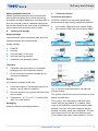
Functional description
FAM-RD is used for two-way radio-based data
transmission through ducting, specifically between:
zone master (ZMA) and zone module (ZMO)
zone module (ZMO) and zone module (ZMO)
Fig. 3: Two-way data transmission via radio link
through ducting
The system uses all the nodes of a network to route
data to its destination.
This is why it is an advantage to have as many
nodes (devices) as possible in a network. Each
node in the RadioDuct network forwards the data
packets it receives from other nodes so that the
packets eventually reach their destination. The net-
work always tries to find the most efficient route.
Such networks are called mesh networks. The con-
Delivery and storage
X-AIRCONTROL FAM-RD 9

nection between the RadioDuct slaves (which are
connected to the zone modules) and the RadioDuct
master (which is connected to the zone master) is
made with a simple procedure using the service
tool.
Security
Radio communication across the entire system is
encrypted and authenticated according to the
AES-128 method. This technology provides high
data security and meets the requirements of the rel-
evant data protection standards.
The transmission output power is adapted to the
transmission distance, 100 mW max. So the system
meets the radio standards applicable to the
2.4 GHz band.
The RadioDuct module allows for frequency hop-
ping to reduce interference caused by other radio
transmitters in the same frequency band. The sys-
tems keeps changing, or hopping, to the radio
channel with the least interference.
Installation example 1
Fig. 4: Radio transmission between zone master
and zone module 1
The connection between the first zone module and
the zone master is made with one FAM-RD at each
end of the transmission route. The zone modules
are interconnected by cables.
Installation example 2
Fig. 5: Radio transmission between zone module 1
and zone module 2
The connection between the first zone module and
the second zone module is made with one FAM-RD
at each end of the transmission route. Zone
module 1 and the zone master as well as zone
modules 2 and 3 are interconnected by cables.
Parts and function
X-AIRCONTROL FAM-RD10

6 Installation
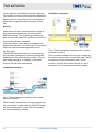
General installation information
Fig. 6: Positioning
Please note:
All modules that should communicate via radio
have to be installed in the same duct system,
i.e. either in the supply air duct or in the extract
air duct.
Place the antenna at least 1 m away from con-
trol dampers, shut-off dampers and measuring
devices.
The distance between the RadioDuct module
and the antenna must not exceed 40 cm.
The distance between the RadioDuct module
and ZMA / ZMO must not exceed 30 m.
Fix the antenna in the middle of the duct wall
(applies to rectangular ducts).
Fig. 7: Position on ducts
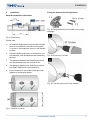
Fixing the antenna mounting bracket
Fig. 8: Fixing material (not included in the supply
package)
Fig. 9: Drill a hole
Æ
10 mm
Fig. 10: Use the screws to fix the bracket
Installation
X-AIRCONTROL FAM-RD 11

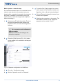
Fig. 11: Insert the antenna so that it locks into place
7 Electrical connection
General information
Connecting the power supply
Personnel:
Skilled qualified electrician
Supply voltage
Ä
‘Technical data’
on page 20
Do not connect more than 5 RadioDuct mod-
ules in series using the double terminals.
Note that a series connection with a zone
master or zone module requires 24 V AC
supply.
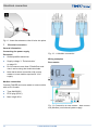
Modbus connection
Connect FAM-RD and zone master or zone module
with an RJ12 cable:
Type AWG26/6C
RJ12 plug (6P6C)
Max. length 30 m
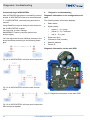
Fig. 12: 1:1 Modbus connection
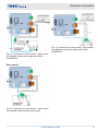
Wiring examples
Zone master
Fig. 13: Connection to zone master – data connec-
tion (Modbus) and external power supply
Electrical connection
X-AIRCONTROL FAM-RD12

Fig. 14: Connection to zone master – data connec-
tion (Modbus) and power supply with X-AIR-
PCASE230 V
Zone module
Fig. 15: Connection to zone module – data connec-
tion (Modbus) and external power supply
Fig. 16: Connection to zone module – data connec-
tion (Modbus) and power supply with X-AIR-
PCASE230 V
Electrical connection
X-AIRCONTROL FAM-RD 13

8 Commissioning
General
Commissioning
RadioDuct module commissioning and radio link
setup are part of commissioning of the X-AIR-
CONTROL single room control system and are
carried out by the HVAC contractor, the system
owner or the TROX Technical Service.
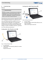
Commissioning requires that the ‘RadioDuct Config
Tool’ configuration software is installed on a PC.
Once the software has been enabled, the PC can
communicate with FAM-RDs. The configuration
software is not only used for commissioning, it also
includes functions for diagnosis and for saving the
settings. To make a connection to the PC, you need
one of the following components:
Configuration cable: EasyConnect-CAB
Fig. 17: EasyConnect-CAB
1 PC (by others)
2 USB–RS485 and connecting cable (for a wired
connection)
EasyConnect-CAB
Configuration cable: EasyConnect-BC
Fig. 18: EasyConnect-BC
1 PC (by others)
2 Bluetooth adapter module BlueCON (for wire-
less connection)
Order code: EasyConnect-BC
Commissioning
X-AIRCONTROL FAM-RD14

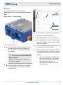
Activation
Activate the system as described below.
Important: Always commission the mesh master
first.
Mesh master – network setup
Fig. 19: Service port T1
1. Connect your PC with the module. To do so,
plug the configuration cable (yellow) into
port ‘Service/T1’ , then start the configura-
tion software.
For connections with a Bluetooth
adapter module:
Make the connection according to the
instructions supplied.
2. Press the [Push Service] (Fig. 19/1) button
on the FAM-RD for 2 seconds to activate
port Service/T1.
3
5
6
7
4
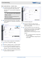
Fig. 20: Zone master configuration for RadioDuct
3. Go to the ‘Configuration’ page.
4. Set the operation mode to ‘Zone master’ .
5. Click on [Generate new network settings] to
have a Pan ID and a network code (128 Bit
AES Key) created.
6. Click on [Transmit changes] to transmit your
entries to the RadioDuct master.
7. Click on [Save network settings] to save the
network parameters on your PC so that you
can use them later for other other network
devices.
ðOnce the integration is complete and
the connections to the zone modules
have been established, you can con-
figure the zone master, Ä ‘X-
AIRCONTROL commissioning and
service manual’ .
Commissioning
X-AIRCONTROL FAM-RD 15

Mesh nodes (devices) – network setup
1. Connect your PC with the module. To do so,
plug the configuration cable (yellow) into
port Service/T1, then start the configuration
software.
For connections with a Bluetooth
adapter module:
Make the connection according to the
instructions supplied.
2. Press the [Push Service] (Fig. 19/1) button
on the module for 2 seconds to activate port
Service/T1.
3
4
5
6
Fig. 21: Zone module configuration for RadioDuct
3. Go to the ‘Configuration’ page.
4. Set the ‘Operation mode’ to ‘Zone module’ .
5. To use the Pan ID and network key saved
earlier as part of the RadioDuct master con-
figuration, click on [Load network settings].
6. Click on [Transmit changes] to transmit your
entries to the zone module.
7
Fig. 22: RadioDuct diagnosis
7. Go to the ‘Diagnosis’ page to check
whether the connection to the master has
been correctly made.
8. To find out whether the zone master has
assigned the zone modul a correct address,
see the segmented display of the X-AIR-
CONTROL zone module Ä ‘X-
AIRCONTROL commissioning and service
manual’ .
ð99 = no address has been assigned by
the zone master
1 – 25 = valid address assigned by the
zone master
Commissioning
X-AIRCONTROL FAM-RD16

Mesh repeater – network setup
If a connection tends to fail of if a connection from a
network node (device) to the master has a poor
signal quality, a repeater is required in the transmis-
sion path. A repeater is just another node in the
mesh network; it receives a signal and amplifies it
before forwarding it.
1. Connect your PC with the module. To do so,
plug the configuration cable (yellow) into
port Service/T1, then start the configuration
software.
For connections with a Bluetooth
adapter module:
Make the connection according to the
instructions supplied.
2. Press the [Push Service] (Fig. 19/1) button
on the module for 2 seconds to activate port
Service/T1.
3
4
5
6
Fig. 23: Repeater configuration for RadioDuct
3. Go to the ‘Configuration’ page.
4. Set the ‘Operation mode’ to ‘Repeater’ .
5. To use the Pan ID and network key saved
earlier as part of the RadioDuct master con-
figuration, click on [Load network settings].
6. Click on [Transmit changes] to transmit your
entries to the repeater.
7. Checking the connection to the master: The
radio status is shown on the ‘Diagnosis’
page and on the module, Fig. 22.
Commissioning
X-AIRCONTROL FAM-RD 17

Commissioning X-AIRCONTROL
After all FAM-RDs have been successfully commis-
sioned, X-AIRCONTROL has to be commissioned
Ä ‘X-AIRCONTROL commissioning and service
manual’ .
Using RadioDuct requires that you set a timeout in
the X-AIRCONTROL master.
You can enter it under ‘Settings
è MODBUS Timeout’ (requires special user
access rights).
You can adjust the timeout (Modbus timeout) to the
actual conditions according to the following exam-
ples:
Fig. 24: X-AIRCONTROL with one mesh connection
Fig. 25: X-AIRCONTROL with two mesh connec-
tions
Fig. 26: X-AIRCONTROL with one mesh connection
that includes a repeater
9 Diagnosis / troubleshooting
Diagnosis information in the configuration soft-
ware
The following status information displays:
Radio status
Signal quality:
– green (1 – 2) = good
– yellow (2 – 3) = sufficient
– red (3 – 5) = poor
Signal time [ms]
Connection loss (counter)
Network address
Device ID
Diagnosis information on the main PCB
Fig. 27: Diagnosis information on the main PCB
Diagnosis / troubleshooting
X-AIRCONTROL FAM-RD18

(1) Yellow LED (CONFIG)
On - The connection between FAM and the
RadioDuct expansion module has been
established.
Off - No connection between FAM and the
RadioDuct expansion module
Blinking - Data transmission from FAM to the
RadioDuct expansion module is in pro-
gress. The blinking frequency depends
on the data transmission rate.
(2) Red LED (SYSTEM)
On - Device not configurated
Off - Device OK
(3) Green LED (SYSTEM)
On - Normal (error free) system opera-
tion
Off - Normal system operation or no
voltage
Blinking,
2 Hz
- Heartbeat controller is working
(4) Red LED (ALARM)
Off - Not used, LED remains off
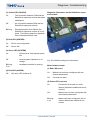
Diagnosis information on the RadioDuct expan-
sion module
Fig. 28: RadioDuct diagnosis information
Mesh network master
(1) Red LED (error)
On - Module has not been configured with the
network parameters
Off - Currently no alarm
(2) Green LED (connect)
On - Connection to at least one node
(device) has been established and is
working
Off - Module has not been configured with
the network parameters
Blinking,
1 Hz
- Master has been configured, but no
network device has initiated a con-
nection
Diagnosis / troubleshooting
X-AIRCONTROL FAM-RD 19

(3) Yellow LED (data)
Blinking - Data transmission in progress, blinking
frequency depends on data transmis-
sion rate
Mesh network devices and mesh repeaters
(1) Red LED (error)
On - Module has not been configured
with the network parameters
Off - Currently no alarm
Blinking,
2 Hz
- ETX value > 3 = network connec-
tion with poor signal quality
(2) Green LED (connect)
On - Connection to radio network has
been correctly established
Off - Module has not been connected to a
radio network
Blinking,
1 Hz
- Connection to the network is being
established (state: network calibra-
tion)
Blinking,
2 Hz
- Connection to the network is being
established (state: network assign-
ments)
(3) Yellow LED (data)
Blinking - Data transmission in progress, blinking
frequency depends on data transmis-
sion rate
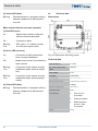
10 Technical data
Dimensions
Fig. 29: Dimensions and fixing points
Technical data
Radio frequency 2.4 GHz
Max. radio transmission
output
100 mW
Power rating 5 VA
Encryption 128 bit AES
Power supply 24 V AC or DC
IEC protection class III (protective extra-low
voltage)
Ambient temperature 10 to 50 °C
Protection level IP20
CE conformity EMC directive
2014/30/EU
RoHS 2011/65/EU
Radio equipment
directive ‘RED
2014/53/EU’
Weight 500 g
Technical data
X-AIRCONTROL FAM-RD20
La pagina si sta caricando...
La pagina si sta caricando...
La pagina si sta caricando...
La pagina si sta caricando...
-
 1
1
-
 2
2
-
 3
3
-
 4
4
-
 5
5
-
 6
6
-
 7
7
-
 8
8
-
 9
9
-
 10
10
-
 11
11
-
 12
12
-
 13
13
-
 14
14
-
 15
15
-
 16
16
-
 17
17
-
 18
18
-
 19
19
-
 20
20
-
 21
21
-
 22
22
-
 23
23
-
 24
24


Trox FAM-RADIODUCT Guida d'installazione
- Tipo
- Guida d'installazione
in altre lingue
Documenti correlati
Altri documenti
-
WAGO Fieldbus Coupler Modbus TCP M12 Manuale utente
-
VIPA CPU 019-CEFPM00 Manuale del proprietario
-
-
-
-
YASKAWA VIPA System SLIO Manuale utente
-
-
-
CAME AGATAKIT/X1-DVC Guida d'installazione
-
ELPRO LIBERO Ti1-S Manuale utente