ProLights LED Fresnel pole operated Manuale utente
- Categoria
- Stroboscopi
- Tipo
- Manuale utente

USER MANUAL
MANUALE UTENTE
ECLFRJPTU-DY
EN - IT
POLE OPERATED FRESNEL PROJECTOR

All rights reserved by Music & Lights S.r.l. No part of this instruction manual may be
reproduced in any form or by any means for any commercial use.
In order to improve the quality of products, Music&Lights S.r.l. reserves the right to modify the
characteristics stated in this instruction manual at any time and without prior notice.
All revisions and updates are available in the ‘manuals’ section on site www.musiclights.it
REV.01-04/20

1
ECLFRJPTU - DY
Packing content
• ECLFRJPTU-DY
• ECLIPSEFRSJBD
• ECLFRSPG
• Power cable
• User manual
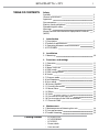
TABLE OF CONTENTS
Safety
SymbolsSymbols
General instructionsGeneral instructions
ApprovalsApprovals
Fire preventionFire prevention
Electric shock preventionElectric shock prevention
Photobiological safetyPhotobiological safety
WarningsWarnings
Waste Electrical and Electronic Equipment Directive Waste Electrical and Electronic Equipment Directive
(WEEE)(WEEE)
1 Introduction
1. 1 Description1. 1 Description
1. 2 Technical specications1. 2 Technical specications
1. 3 Operating elements and connections1. 3 Operating elements and connections
1. 4 ECLFRSJBP41. 4 ECLFRSJBP4
2 Installation
2. 1 Mounting2. 1 Mounting
3 Functions and settings
3. 1 Operation3. 1 Operation
3. 2 Basic3. 2 Basic
3. 3 Menu structure3. 3 Menu structure
3. 4 DMX mode3. 4 DMX mode
3. 5 DMX conguration3. 5 DMX conguration
3. 6 Screen3. 6 Screen
3. 7 Dimmer mode3. 7 Dimmer mode
3. 8 Led frequency3. 8 Led frequency
3. 9 Fans mode3. 9 Fans mode
3. 10 Factory Reload3. 10 Factory Reload
3. 11 Fixture Information3. 11 Fixture Information
3. 12 Maste/Slave3. 12 Maste/Slave
3. 13 Eects3. 13 Eects
3. 14 Static3. 14 Static
3. 15 Connection of the DMX line3. 15 Connection of the DMX line
3. 16 Construction of the DMX termination3. 16 Construction of the DMX termination
3. 17 Channels DMX3. 17 Channels DMX
4 Maintenance
4. 1 Maintenance and cleaning the unit4. 1 Maintenance and cleaning the unit
4. 2 Fuse replacement4. 2 Fuse replacement
4. 3 Trouble shooting4. 3 Trouble shooting
2
3
3
3
3
4
4
4
5
7
7
8
10
11
11
12
13
13
13
14
14
14
14
14
15
15
15
16
16
17
18
18
19

ECLFRJPTU - DY
2
WARNING! Before carrying out any operations with the unit, carefully read this instruction
manual and keep it with cure for future reference. It contains important information about
the installation, usage and maintenance of the unit.
T 45°C
a
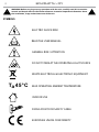
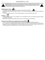
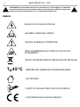
ELECTRIC SHOCK RISK
READ THE USER MANUAL
GENERAL RISK / ATTENTION
DO NOT STARE AT THE OPERATING LIGHT SOURCE
WASTE ELECTRICAL & ELECTRONIC EQUIPMENT
MAX OPERATING AMBIENT TEMPERATURE
INDOOR USE
FIXING POINT FOR SAFETY CABLE
EUROPEAN UNION CONFORMITY
SYMBOLS

3
ECLFRJPTU - DY
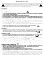
SAFETY
General instruction
• This unit is not for home use, only professional applications.
• The connection to the main network of electric distribution must be carried out by a qualied electrical
installer.
• Before starting any maintenance work or cleaning the projector, cut o power from the main supply.
• Connection must be made to a power supply system tted with ecient earthing (Class I appliance ac-
cording to standard EN 60598-1). It is, moreover, recommended to protect the supply lines of the units
from indirect contact and/or shorting to earth by using appropriately sized residual current devices.
• Do not modify the unit in any way not described in this manual or install parts other than the original
Music & Lights parts. Do not apply lters, lenses or other materials on lenses or other optical compo-
nents. Use only accessories approved by Music & Lights.
• If this device will be operated in any way dierent to the one described in this manual, it may suer
damage and the guarantee becomes void.
• We decline any liability deriving from improper use of the product.
Approvals
• The products referred to in this manual conform to the European Community Directives LVD (Low Volt-
age Directive) 2014/35 / EC, EMC (Electromagnetic Compatibility Directive) 2014/30 / EU, RoHS (Restric-
tion of Hazardous Substances Directive) 2011/65 / CE and are therefore marked with .
Fire prevention
• The minimum distance between the projector and the surrounding walls and ammable materials
must be greater than 50 cm and the ventilation openings must in no case be blocked.
• Replace a defective, blown or damaged fuse only with one of the same type. To replace the fuse, refer
to the “Maintenance” paragraph.
• Do not use the unit if the ambient temperature exceeds 45 ° C (122 ° F).
• The surface of the appliance can reach up to 50 ° C (158 ° F) during operation. Avoid contact with peo-
ple and materials.
• Make sure there is a free and unobstructed air ow around the appliance.
Electric shock prevention
• The unit is supplied with hazardous network voltage (230V~). Leave servicing to skilled personnel only.
Never make any modications on the unit not described in this instruction manual, otherwise you will
risk an electric shock.
• Disconnect power to the unit when not in use.
• Install the xture in a well ventilated place.
• Refer to any service operation not described in this manual to Music & Lights technical support.
• Isolate the unit immediately from the power supply if any gaskets, covers, cables or other components
are damaged, defective, deformed or showing signs of overheating. Do not reapply power until repairs
are complete. Before using the unit, check that all components and power distribution cables are in
perfect condition.Check that the frequency and voltage of the network correspond to the frequency
and voltage for which the unit is set up, indicated on the electrical data plate.
WARNING! Before carrying out any operations with the unit, carefully read this instruction
manual and keep it with cure for future reference. It contains important information about
the installation, usage and maintenance of the unit.
T 45°C
a
0,5 m

ECLFRJPTU - DY
4
Photobiological safety
• This device is a product identied in risk group 2 according to EN 62471.
• Emits potentially dangerous optical radiation. It falls into the categories of the risk group according to
EN 62471.
• Do not look directly at the LED source during operation. It can be harmful to the eyes.
Warnings
• This device is rated IP20. It is not suitable for use in humid places. Never use the xture in places subject
to vibrations or bumps.
• Make certain that no inammable liquids, water or metal objects enter the xture.
Waste Electrical and Electronic Equipment Directive (WEEE)
• The unit, accessories and packaging should be sorted for environmetal-friendly recycling.
• For EC countries: according to the European Directive 2012/19/EC for Waste Electrical and Electronic
Equipment and its implementation into national right, luminaires that are no longer usable must be
collected separately and disposed of in an environmentally correct manner.
WARNING! Before carrying out any operations with the unit, carefully read this instruction
manual and keep it with cure for future reference. It contains important information about
the installation, usage and maintenance of the unit.

5
ECLFRJPTU - DY
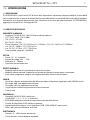
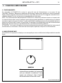
- 1 - INTRODUCTION
1.1 DESCRIPTION
ECLIPSEFRESNELJ is the LED replacement for a standard tungsten 650 W Fresnel. Featuring the output
characteristics of the traditional Fresnel, with beam control from functional barn doors and a powerful
source that focuses on outstanding colour rendering. The ECLIPSEFRESNELJ adds all the advantages of
LED to the Fresnel.
1.2 TECHNICAL SPECIFICATIO
LIGHT SOURCE
• Source:(TU) 69 W (DY) 74 W high-power white LED
• CCT:(TU) 3.100 K - (DY) 5.600 K
• CRI:(TU) 97 - (DY) 90
• R9:(TU) 97 - (DY) 54
• Luminous ux:(TU) (15°) 3’018 lm (51°) 4’549 lm - (DY) (15°) 3’847 lm (51°) 5’903 lm
• Lux:TU (15°) 3’630 lx - (51°) 775 lx @3 m
• Lux:DY (15°) 4’770 lx - (51°) 772 lx @3 m
• Source life expectancy: > 50.000 h
OPTICS
• Zoom:15 ° - 51 ° manual
• Field angle:26,7 ° - 75,6 °
• Lens diameter:6’’ - 150 mm
• Lens type:fresnel zoom lens
DYNAMIC EFFECTS
• Static colour mode: selection of static colour
• Manual colour mode: manual adjust of dimmer throught menu and knob
• Auto mode: built-in programs with execution speed adjustment
BODY
• Hardware on-board:included lter frame, 8 doors barndoor, omega bracket spigot
• Pan angle:360 ° with manual regulation
• Tilt angle:340 ° with manual regulation
• Body: sturdy die-cast aluminium body conceived for long-time durability
• Body colour: black
CONTROL
• Protocols: DMX512, RDM, local knob
• DMX channels:1 / 2 - 1 / 2 - 2 / 3 / 5 channel
• RDM: RDM ready for xture remote monitor and settings
• Display: black OLED high resolution display
• Firmware upgrade: yes, via USB - DMX interface (UPBOX1) not included
• Other: 16bit control of dimmer and colour
ELECTRONICS
• Dimmer: linear 0 ~ 100% electronic dimmer

ECLFRJPTU - DY
6
• Dimmer curves:4 dierent dimming curves available
• Strobe / shutter:0 ~ 30 Hz, electronic
• Operating temperature: -10° ~ +45°
• Flicker: icker free frequency with adjustable PWM
• Selectable PWM: 600 ~ 25.000 Hz
ELECTRICAL
• Power supply: 100-240 V – 50/60 Hz
• Power consumption (at 230 V):82,7 W
• Power consumption (at 120 V):83,3 W
• Output (at 230 V):30 units on a single power line
• Output (at 120 V):16 units on a single power line
BATTERY
• Battery:29,6 V 4400 mAh (optional) external battery
• Re-charge connection: XLR 4p
PHYSICAL
• Cooling: forced air with low noise fan
• Sospension and xing: hanging bracket suitable for safe hanging and positioning
• Signal connection: Amphenol XLR 5p IN/OUT connectors
• Power connection: Neutrik powerCON TRUE1 IN/OUT connectors
• IP rating:20
• Dimensions (WxHxD):297x497x260 mm
• Weight:6 kg
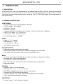
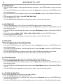
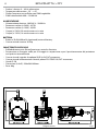
Technical drawing Fig.1

Fig.2
5
6
7
3
4
2
1
13
10
9
14
15
16
17
8
11
12
7
ECLFRJPTU - DY
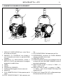
1.3 OPERATING ELEMENTS AND CONNECTIONS
1. VENTILATION GRID for air ow outlet not to be
obstructed.
2. CONTROL PANEL with display and a knob
used to access the control panel functions
and manage them.
3. ZOOM ADJUSTMENT AND FOCUS knob to
zoom the projected image clearly.
4. LENS
5. SPIGOT
6. POLE OPERATED BRACKET
7. GUIDE for locking and releasing accessories.
8. HANDLE
9. YELLOW POLE OPERATOR: Zoom pole
operator.
10. WHITE POLE OPERATOR: Tilt pole operator.
11. BLUE POLE OPERATOR: Pan pole operator.
12. MAIN FUSE HOLDER: replace a burnt-out fuse
by one of the same type only
13. BATTERY 4pin-in.
14. POWER IN (PowerCON IN): for connection to
a socket (100-240V~/50-60Hz) via the sup-
plied mains cable.
15. DMX IN (5-pole XLR): 1 = ground, 2 = DMX-, 3
= DMX+, 4 N/C, 5 N/C.
16. DMX OUT (5-pole XLR): 1 = ground, 2 = DMX-,
3 = DMX+, 4 N/C, 5 N/C.
17. POWER OUT (PowerCON OUT): power output
for connection of multiple units in series.

ECLFRJPTU - DY
8
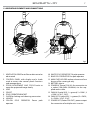
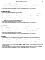
Fig.4
1
3
8
5
4
7
4
3
2
10
9
6
442
355
175
Fig.3
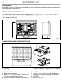
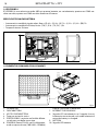
1.4 ECLFRSJBP4
ECLFRSJBP4 is a sturdy ABS case with four battery, a charger for them, four DMX cable male to male, four
DMX cable male to female inside
BATTERY TECHNICAL SPECIFICATIONS
• Estimated battery life in single colour mode up to:(R) 8 h - (G) 8 h - (B) 7 h - (L) 3 h - (O) 4 h - (RB) 7 h
• Estimated battery life in full-mode up to:(TW) 1,25 h - (TU, DY) 1,5 h
• Re-charge time:5 h/max
1.5 OPERATING ELEMENTS AND CONNECTIONS
1. ABS case
2. CHARGER
3. CHARGER OUT
4. Button to start charging
5. MAIN FUSE HOLDER: replace a burnt-out
fuse by one of the same type only
6. POWER IN (PowerCON IN): for connection to
a socket (100-240V~/50-60Hz) via the supplied
mains cable.
7. SWITCH
8. Charger status LED: if it is red, the battery is
charging, if it is green, the battery is charged.
9. BATTERY
10. Battery status LED

9
ECLFRJPTU - DY
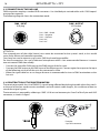
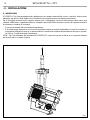
Fig.5
Fig.6
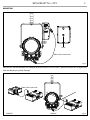
MOUNTING
Holes
DMX cable male-female
DMX cable male-male
CORRECT WRONG
IMPORTANT: do not connect this charger directly to the ECLIPSEFESNELJ, please connect this charger only
with the battery as power charger.

Fig.7
ECLFRJPTU - DY
10
- 2 - INSTALLATION
2.1 MOUNTING
ECLFRJPTU-DY is designed for applications in exhibition areas, commercial spaces, museums, restaurant,
churches, and any other installation where size is an important factor. For xing, stable mounting clips are
required. The mounting place must be of sucient stability and be able to support a weight of 10 times
of the unit’s weight.
When carrying out any installation, always comply scrupulously with all the regulations (particularly re-
garding safety) currently in force in the country in which the xture’s being used.
• Install the projector at a suitable location.
• Always additionally secure the projector with the safety rope from falling down. For this purpose, fas-
ten the safety rope at a suitable position so that the maximum fall of the projector will be 20 cm. The
adjust the projector and use the knobs.
NOTE - For the installation of the ECLFRJPTU-DY make sure that the ridge of the adaptor is in with the
groove of the track..

11
ECLFRJPTU - DY
- 3 - FUNCTIONS AND SETTINGS
3.1 OPERATION
To turn on the ECLFRJPTU-DY connect the supplied main cable to a socket (100-240 VAC-50/60 Hz). Then
the unit is ready for operation. You can also adjust the dimmer and zoom using the knobs.
To switch o, disconnect the mains plug from the socket. For a more convenient operation it is recom-
mended to connect the unit to a socket which can be switched on and o via a light switch.
NOTE - To operate the projector ECLFRJPTU-DY you need a system track. The track system must be in-
stalled and maintained by a suitably qualied person in compliance with latest construction and relevant
legislation. It is the responsibility of the installer to ensure the electrical, mechanical and thermal com-
patibility of the track system and the ttings. The connection to the main network of electric distribution
must be carried out by a qualied electrical installer.
ATTENTION - Mains voltage must be switched o before mounting; maintenance; insert and replace
Adaptors; spots and luminaires.
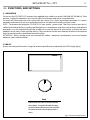
3.2 BASIC
Access control panel functions using the knob located directly underneath the LED Display (g.8).
Fig.8- Functions of the buttons
Knob
Used to access the menu, to return a previous
menu option, to navigate through the menu,
to select and store the current menu or conrm
the current function value or option within a
menu

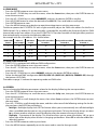
MENU
1 CONNECT
ð
DMX Address
ð
Value (001-512)
DMX Mode
ð
EASY-1Ch
BASIC-2Ch 1
BASIC-2Ch 2
BASIC-3Ch
STANDARD–5CH
2 SETUP
ð
Screen
ð
Back Light
ð
On
10S
20S
30S
ð
Flip Display
ð
NO-Yes
3 ADVANCED
ð
Dimmer Mode
ð
O
Dimmer 1
Dimmer 2
Dimmer 3
Led Frequency
ð
600Hz
1200 Hz
2000 Hz
4000 Hz
6000Hz
25kHZ
Fan Mode
ð
Auto
On
Factory Reload
ð
NO-Yes
4 INFORMATION
ð
Fixture TIme
ð
0-9999
Version
ð
V1.0
UID
ð
15D00219****
5 STAND ALONE
ð
Master/Slave
ð
Master
Slave
Eect
ð
Eect 1
Eect 2
Eect 3
Eect 4
ð
<1-100>
Static
ð
Dimmer
Strobe
ð
<0-255>
ECLFRJPTU - DY
12
3.3 MENU STRUCTURE

13
ECLFRJPTU - DY
3.4 DMX MODE
• Press the ENTER button to access the main menu.
• Press the UP / DOWN keys to scroll the menu, select the Connect icon, then press the ENTER button to
enter the next menu.
• Press the UP / DOWN keys to select DMX ADDRESS, and press the button ENTER to conrm.
• Press UP/DOWN button to select the desired value (001-512). Press and hold to scroll quickly.
• Press ENTER button to store.
• Press the MENU button to go back or to meet the waiting time to exit the setup menu.
To able to operate the ECLFRJPTU-DY with a light controller, adjust the DMX start address for the rst a
DMX channel. If e. g. address 33 on the controller is provided for controlling the function of the rst DMX
channel, adjust the start address 33 on the ECLFRJPTU-DY. The other functions of the light eect panel are
then automatically assigned to the following addresses.
An example with the start address 33 is shown below:
3.5 DMX CONFIGURATION
ECLFRJPTU-DY is equipped with dierent DMX conguration.
• Press the ENTER button to access the main menu.
• Press the UP / DOWN keys to scroll the menu, select the Connect icon, then press the ENTER button to
enter the next menu.
• Press the UP / DOWN keys to select DMX MODE, and press the button ENTER to conrm.
• Select the desired DMX conguration (EASY-1Ch, BASIC-2Ch 1, BASIC-2Ch 2, BASIC-3Ch, STANDARD–5CH) through
the buttons UP/DOWN.
The tables on page 15 indicate the operating mode and DMX value.
3.6 SCREEN
You can change the following parameters related to the display, following the same procedure:
• Press the ENTER button to access the main menu.
• Press the UP / DOWN keys to scroll the menu, select the Set Up icon, then press the ENTER button to
enter the next menu.
• Press UP / DOWN to scroll through the menu, then select Screen, and press the ENTER button to enter
the next menu.
• Press UP / DOWN to scroll through the menu, and then select one of the following settings for the dis-
play and press the ENTER key to display it.
- Back Light - Backlight display Auto O. This feature allows you to automatically turn o the backlight
after a specied time that you can set using the arrow buttons. To have the display always on select
On or choose another value to turn o the display after the amount of time you choose.
- Flip Display - Orientation of the display. This function allows you to rotate the display 180° to get a
better view of the display when the unit is hanging upside down. Select YES to activate or NO to dis-
able this function.
• Press the ENTER button to conrm your choice.
• Press the MENU button repeatedly to exit the menu and to save the changes made.
Number DMX
channels
Address of
start (example)
DMX address
occupied
Next possible start address
for unit No. 1
Next possible start address
for unit No. 2
Next possible start address
for unit No. 3
1 33 33 34 35 36
2 33 33-34 35 37 39
3 33 33-35 36 39 42
5 33 33 - 37 38 43 48

ECLFRJPTU - DY
14
3.7 DIMMER MODE
• Enter in Dimmer mode to select specic dimming curve, press the ENTER button to access the main
menu.
• Press the UP/DOWN keys to scroll the menu, select the Advanced icon, then press the ENTER button to
enter the next menu.
• Press UP/DOWN to scroll through the menu, then select DIM MODE, and press the button ENTER to con-
rm.
• Press the button UP/DOWN to select OFF - DIM1 - DIM2 - DIM3.
• Press ENTER button to store.
• Press the MENU button repeatedly to exit the menu and to save the changes made.
3.8 LED FREQUENCY
• To adjust the frequency of the LEDs, press the ENTER button to access the main menu.
• Press the UP/DOWN keys to scroll the menu, select the Advanced icon, then press the ENTER button to
enter the next menu.
• Press UP/DOWN to scroll through the menu, then select LED Frequency, and press the button ENTER to
conrm.
• Select the frequency (600Hz - 1200Hz - 2000Hz - 4000Hz - 6000Hz - 25kHz) using the UP/DOWN buttons.
• To conrm, press the ENTER key.
• Press the MENU button repeatedly to exit the menu and to save the changes made..
3.9 FANS MODE
Select this function to set the fans operation mode:
• Press the ENTER button to access the main menu.
• Press the UP/DOWN button to scroll the menu, select the Advanced, then press the ENTER button to
enter the next menu.
• Press the UP/DOWN button to scroll through the menu, select Fans Mode, and press the ENTER button
to enter the next menu.
• Press the UP/DOWN button to select Auto/On, press the ENTER button to conrm your choice.
• Press the MENU button repeatedly to exit the menu and to save the changes made..
3.10 FACTORY RELOAD
Selezionare questa funzione per ripristinare l’unità alle impostazioni di fabbrica:
• To activate Reset Factory display press the ENTER button to access the main menu.
• Press the UP/DOWN keys to scroll the menu, select the Advanced icon, then press the ENTER button to
enter the next menu.
• Press UP/DOWN to scroll through the menu, then select Factory Reload, and press the button ENTER to
conrm.
• Press the MENU button repeatedly to exit the menu and to save the changes made.u.
3.11 FIXTURE INFORMATION
To view all the information on the device, proceed as follows:
• Press the ENTER button to access the main menu.
• Press the UP/DOWN button to scroll the menu, select the icon Information, then press the ENTER button
to enter the next menu.
• Press the UP/DOWN button to scroll through the menu, then select one of the following information

15
ECLFRJPTU - DY
and press the ENTER button to display it.
- Fixture Time - Through the Fixture Time function you can display the operating time of the projector.
- Software Version - Through Version function you can display the currently installed software version.
- UID - This option shows the RDM identication number.
• Press the MENU button repeatedly to exit the menu and to save the changes made.
3.12 MASTER SLAVE
• Press the ENTER button to access the main menu.
• Press the UP/DOWN button to scroll the menu, select the Stand Alone icon, then press the ENTER button
to enter the next menu.
• Press the UP/DOWN button to scroll through the menu, select Master/Slave and press ENTER to conrm
your choice.
• Press the UP/DOWN button to select the mode of operation:
- Master, if the unit is connected in series with other units and it acts as the Master;
- Slave, if the unit is not connected to other units.
• Press the ENTER button to conrm your choice.
• Press the MENU button repeatedly to exit the menu and to save the changes made.
3.13 EFFECTS
The unit has pre-programmed eects that can be set through the following procedure:
• Press the ENTER button to access the main menu.
• Press the UP/DOWN button to scroll the menu, select the Eects icon, then press the ENTER button to
enter the next menu.
• Press the UP/DOWN button to select the mode of operation: Eects 1, Eects 2, Eects 3, Eects 4.
• Press the ENTER button to conrm your choice.
• Press the MENU button repeatedly to exit the menu and to save the changes made.
3.14 STATIC
• The unit allows you to create congurations that can be set through the following procedure:
• To enter to static static mode, Press the ENTER button to access the main menu.
• Press the UP/DOWN button to scroll the menu, select the Stand Alone icon, then press the ENTER button
to enter the next menu.
• Press the UP/DOWN button to scroll through the menu, select Static and press ENTER to conrm your
choice.
• Throught the UP/DOWN buttons select DIMMER o STROBE and press the ENTER button to conrm the
desired function.
• Set the value (000 - 255), Throught the UP/DOWN buttons, then press the ENTER button to conrm
• Press the MENU button repeatedly to exit the menu and to save the changes made.

ECLFRJPTU - DY
16
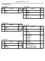
Fig.9
Fig.10
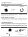
3.15 CONNECTION OF THE DMX LINE
DMX connection employs standard XLR connectors. Use shielded pair-twisted cables with 120Ω imped-
ance and low capacity.
The following diagram shows the connection mode:
ATTENTION
The screened parts of the cable (sleeve) must never be connected to the system’s earth, as this would
cause faulty xture and controller operation.
Over long runs can be necessary to insert a DMX level matching amplier.
For those connections the use of balanced microphone cable is not recommended because it cannot
transmit control DMX data reliably.
• Connect the controller DMX input to the DMX output of the rst unit.
• Connect the DMX output to the DMX input of the following unit. Connect again the output to the input
of the following unit until all the units are connected in chain.
• When the signal cable has to run longer distance is recommended to insert a DMX termination on the
last unit.
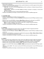
3.16 CONSTRUCTION OF THE DMX TERMINATION
The termination avoids the risk of DMX 512 signals being reected back along the cable when they reach-
es the end of the line: under certain conditions and with certain cable lengths, this could cause them to
cancel the original signals.
The termination is prepared by soldering a 120Ω 1/4 W resistor between pins 2 and 3 of the 5-pin male XLR
connector, as shown in gure.
DMX - OUTPUT
XLR socket
DMX - INPUT
XLR plug
Pin1 : GND - Shield
Pin2 : - Negative
Pin3 : + Positive
Pin4 : N/C
Pin5 : N/C
Example:
5 pin XLR connector

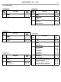
1 CHANNEL
MODE
FUNCTION DMX
Value
1 Ch
1
DIMMER
0~100% 000 - 255
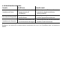
5 CHANNELS
MODE
FUNCTION DMX
Value
5 Ch
1
DIMMER
0~100% 000 - 255
2
STROBE
No Function
Strobe slow to fast
000 - 010
011 - 255
3
AUTO PROGRAMS
No Function
Auto Program 1
Auto Program 2
Auto Program 3
Auto Program 4
000 - 010
011 - 070
071 - 130
131 - 190
191 - 255
4
AUTO SPEED
Speed slow to fast 000 - 255
5
DIMMER SPEED MODE
Preset dimmer speed from display menu
Dimmer speed mode o
Dimmer speed mode1 (fast speed)
Dimmer speed mode2 (middle speed)
Dimmer speed mode3 (slow speed)
000 - 051
052 - 101
102 - 152
153 - 203
204 - 255
3 CHANNELS
MODE
FUNCTION DMX
Value
3 Ch
1
DIMMER
0~100% 000 - 255
2
DIMMER FINE
0~100% 000 - 255
3
STROBE
No Function
Strobe slow to fast
000 - 010
011 - 255
2 CHANNELS 1
MODE
FUNCTION DMX
Value
2 Ch1
1
DIMMER
0~100% 000 - 255
2
DIMMER FINE
0~100% 000 - 255
2 CHANNELS 2
MODE
FUNCTION DMX
Value
2 Ch2
1
DIMMER
0~100% 000 - 255
2
STROBE
No Function
Strobe Slow to Fast
000 - 010
011 - 255
17
ECLFRJPTU - DY
3.17 CHANNELS DMX

ECLFRJPTU - DY
18
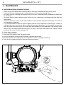
- 4 - MAINTENANCE
4.1 MAINTENANCE AND CLEANING THE UNIT
• Make sure the area below the installation place is free from unwanted persons during setup.
• Switch o the unit, unplug the main cable and wait until the unit has cooled down.
• All screws used for installing the device and any of its parts should be tightly fastened and should not
be corroded.
• Housings, xations and installation spots (ceiling, trusses, suspensions) should be totally free from any
deformation.
• The main cables must be in impeccable condition and should be replaced immediately even when a
small problem is detected.
• It is recommended to clean the front at regular intervals, from impurities caused by dust, smoke, or
other particles to ensure that the light is radiated at maximum brightness. For cleaning, disconnect the
main plug from the socket. Use a soft, clean cloth moistened with a mild detergent. Then carefully wipe
the part dry. For cleaning other housing parts use only a soft, clean cloth. Never use a liquid, it might
penetrate the unit and cause damage to it.
•
4.2 FUSE REPLACEMENT
1. Disconnect this product from the power outlet.
2. Using a screwdriver, unscrew the fuse holder cap from the housing.
3. Remove the blown fuse and replace with a good fuse of the same type and rating.
4. Screw the fuse holder cap back in place and reconnect power
Fig.11
La pagina si sta caricando...
La pagina si sta caricando...
La pagina si sta caricando...
La pagina si sta caricando...
La pagina si sta caricando...
La pagina si sta caricando...
La pagina si sta caricando...
La pagina si sta caricando...
La pagina si sta caricando...
La pagina si sta caricando...
La pagina si sta caricando...
La pagina si sta caricando...
La pagina si sta caricando...
La pagina si sta caricando...
La pagina si sta caricando...
La pagina si sta caricando...
La pagina si sta caricando...
La pagina si sta caricando...
La pagina si sta caricando...
La pagina si sta caricando...
La pagina si sta caricando...
La pagina si sta caricando...
La pagina si sta caricando...
La pagina si sta caricando...
-
 1
1
-
 2
2
-
 3
3
-
 4
4
-
 5
5
-
 6
6
-
 7
7
-
 8
8
-
 9
9
-
 10
10
-
 11
11
-
 12
12
-
 13
13
-
 14
14
-
 15
15
-
 16
16
-
 17
17
-
 18
18
-
 19
19
-
 20
20
-
 21
21
-
 22
22
-
 23
23
-
 24
24
-
 25
25
-
 26
26
-
 27
27
-
 28
28
-
 29
29
-
 30
30
-
 31
31
-
 32
32
-
 33
33
-
 34
34
-
 35
35
-
 36
36
-
 37
37
-
 38
38
-
 39
39
-
 40
40
-
 41
41
-
 42
42
-
 43
43
-
 44
44


ProLights LED Fresnel pole operated Manuale utente
- Categoria
- Stroboscopi
- Tipo
- Manuale utente
in altre lingue
Documenti correlati
-
ProLights LED Fresnel Manuale utente
-
ProLights 13 W professional LED pinspot Manuale utente
-
-
-
-
-
-
-
-