E-flite P-51D Mustang Manuale utente
- Categoria
- Giocattoli telecomandati
- Tipo
- Manuale utente

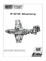
P-51D Mustang
Instruction Manual / Bedienungsanleitung
Manuel d’utilisation / Manuale di Istruzioni

EN
As the user of this product, you are solely responsible for operating in a man-
ner that does not endanger yourself and others or result in damage to the
product or the property of others.
• Always keep a safe distance in all directions around your model to avoid
collisions or injury. This model is controlled by a radio signal subject to
interference from many sources outside your control. Interference can cause
momentary loss of control
• Always operate your model in open spaces away from full-size vehicles,
traffi c and people.
• Always carefully follow the directions and warnings for this and any optional
support equipment (chargers, rechargeable battery packs, etc.).
• Always keep all chemicals, small parts and anything electrical out of the
reach of children.
• Always avoid water exposure to all equipment not specifi cally designed and
protected for this purpose. Moisture causes damage to electronics.
• Never place any portion of the model in your mouth as it could cause serious
injury or even death.
• Never operate your model with low transmitter batteries.
• Always keep aircraft in sight and under control.
• Always use fully charged batteries.
• Always keep transmitter powered on while aircraft is powered.
• Always remove batteries before disassembly.
• Always keep moving parts clean.
• Always keep parts dry.
• Always let parts cool after use before touching.
• Always remove batteries after use.
• Always ensure failsafe is properly set before fl ying.
• Never operate aircraft with damaged wiring.
• Never touch moving parts.
NOTICE
All instructions, warranties and other collateral documents are subject to change at the sole discretion of Horizon Hobby, LLC. For up-to-date product
literature, visit www.horizonhobby.com and click on the support tab for this product.
Meaning of Special Language:
The following terms are used throughout the product literature to indicate various levels of potential harm when operating this product:
NOTICE: Procedures, which if not properly followed, create a possibility of physical property damage AND little or no possibility of injury.
CAUTION: Procedures, which if not properly followed, create the probability of physical property damage AND a possibility of serious injury.
WARNING: Procedures, which if not properly followed, create the probability of property damage, collateral damage, and serious injury OR create a high
probability of superfi cial injury.
WARNING: Read the ENTIRE instruction manual to become familiar with the features of the product before operating. Failure to operate the product
correctly can result in damage to the product, personal property and cause serious injury.
This is a sophisticated hobby product. It must be operated with caution and common sense and requires some basic mechanical ability. Failure to oper-
ate this Product in a safe and responsible manner could result in injury or damage to the product or other property. This product is not intended for use by
children without direct adult supervision. Do not use with incompatible components or alter this product in any way outside of the instructions provided by
Horizon Hobby, LLC. This manual contains instructions for safety, operation and maintenance. It is essential to read and follow all the instructions and warn-
ings in the manual, prior to assembly, setup or use, in order to operate correctly and avoid damage or serious injury.
CAUTION: All instructions and warnings must be followed exactly.
Mishandling of Li-Po batteries can result in a fi re, personal injury, and/or
property damage.
• By handling, charging or using the included Li-Po battery, you assume all
risks associated with lithium batteries.
• If at any time the battery begins to balloon or swell, discontinue use im-
mediately. If charging or discharging, discontinue and disconnect. Continuing
to use, charge or discharge a battery that is ballooning or swelling can result
in fi re.
• Always store the battery at room temperature in a dry area for best results.
• Always transport or temporarily store the battery in a temperature range of
40–120º F (5–49º C). Do not store battery or aircraft in a car or direct sun-
light. If stored in a hot car, the battery can be damaged or even catch fi re.
• Always charge batteries away from fl ammable materials.
• Always inspect the battery before charging and never charge dead or dam-
aged batteries.
• Always disconnect the battery after charging, and let the charger cool
between charges.
• Always constantly monitor the temperature of the battery pack while
charging.
• ONLY USE A CHARGER SPECIFICALLY DESIGNED TO CHARGE LI-PO BATTER-
IES. Failure to charge the battery with a compatible charger may cause fi re
resulting in personal injury and/or property damage.
• Never discharge Li-Po cells to below 3V under load.
• Never cover warning labels with hook and loop strips.
• Never leave charging batteries unattended.
• Never charge batteries outside recommended levels.
• Never attempt to dismantle or alter the charger.
• Never allow minors under the age of 14 to charge battery packs.
• Never charge batteries in extremely hot or cold places (recommended be-
tween 40–120° F or 5–49° C) or place in direct sunlight.
Safety Precautions and Warnings
Charging Warnings
14
+
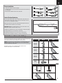
AGE RECOMMENDATION:
Not for children under 14
years. This is not a toy.
WARNING AGAINST COUNTERFEIT PRODUCTS: If you ever need to replace your Spektrum receiver found
in a Horizon Hobby product, always purchase from Horizon Hobby, LLC or a Horizon Hobby authorized dealer to en-
sure authentic high-quality Spektrum product. Horizon Hobby, LLC disclaims all support and warranty with regards,
but not limited to, compatibility and performance of counterfeit products or products claiming compatibility with
DSM or Spektrum.
2

EN
1 Remove and inspect contents.
2 Read this instruction manual thoroughly.
3 Charge the fl ight battery.
4 Fully assemble the airplane.
5 Setup Transmitter using transmitter setup chart.
6 Install the fl ight battery in the aircraft (once it has been fully charged).
7 Check the Center of Gravity (CG).
8 Bind the aircraft to your transmitter.
9 Make sure linkages move freely.
10 Test the retract operation.
11 Test the fl ap operation.
12 Perform the Control Direction Test with the transmitter.
13 Perform the AS3X Control Direction Test with the aircraft.
14 Adjust fl ight controls and transmitter.
15 Perform a radio system Range Test.
16 Find a safe open area to fl y.
17 Plan fl ight for fl ying fi eld conditions.
To register your product online, visit www.e-fl iterc.com
Table of Contents
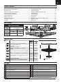
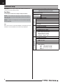
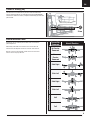
42.8 oz
(1214 g)
Model Assembly ................................................................................4
Control Horn and Servo Arm Settings .................................................5
Transmitter Setup .............................................................................6
PNP Receiver Selection and Installation .............................................7
Transmitter and Receiver Binding .......................................................7
Battery Installation and ESC Arming ...................................................8
Center of Gravity (CG) .......................................................................9
Control Direction Tests .......................................................................9
AS3X Control Direction Test ............................................................10
Flying Tips and Repairs ....................................................................11
Post Flight .......................................................................................12
Power Component Service ...............................................................12
Troubleshooting Guide AS3X ...........................................................13
Troubleshooting Guide .....................................................................14
AMA National Model Aircraft Safety Code .........................................15
Limited Warranty .............................................................................16
Contact Information .........................................................................17
FCC Information ...............................................................................17
IC Information ..................................................................................17
Compliance Information for the European Union ...............................17
Replacement Parts ...........................................................................62
Optional Parts ..................................................................................63
Specifi cations
BL15 Brushless Outrunner Motor, 950Kv (PKZ5116) Installed Installed
E-fl ite 30-Amp Pro Brushless ESC
(EFLA1030B)
Installed Installed
(2) Aileron Servos (PKZ1081)
(1) Rudder Servo (1) Elevator Servo (1) Flap Servo
(PKZ1090)
Installed Installed
Spektrum
™
AR636, 6-Channel Sport Receiver (SMAR636) Installed
Required to
Complete
Battery: 11.1V 3S 2200mAh 30C Li-Po (EFLB22003S30)
Required to
Complete
Required to
Complete
Battery Charger: 3-cell Li-Po battery balancing charger
Required to
Complete
Required to
Complete
Recommended Transmitter:
Full-Range 6 channel (or more) 2.4GHz with Spektrum
DSM2
®
/DSMX
®
technology with adjustable Dual Rates.
Required to
Complete
Required to
Complete
Prefl ight
Box Contents
Quick Start Information
Transmitter
Setup
Setup your transmitter using the
transmitter setup chart.
Dual Rates
High Low
100% 70%
Flight Timer
Setting
First fl ight 5 Min. 7 Min.
44 in (1120mm)
38.4 in (975mm)
3

EN
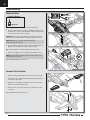
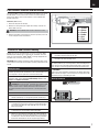
Model Assembly
Wing Installation
1. Connect the fl ap servo connector to the receiver port number 6.
2. Connect the retract Y-harness connectors to the GEAR port number 5 and
the aileron servo connectors to the AILE Y-harness. The left and right servos
can be connected to either side of a Y-harness.
IMPORTANT: Correct operation of the AS3X
®
system requires connection of
both ailerons to the included Y-harness and the AILE channel of the receiver.
NOTICE: DO NOT crush or otherwise damage the wiring when
attaching the wing to the fuselage.
4. Insert the guide pins (A) on the rear of the wing in the fuselage plate holes
(B), then connect the wing to the fuselage using 2 screws (C).
Tip: Carefully support the aircraft while installing or removing screws.
5. Install the scoop (D) on the rear of the wing using medium CA as shown.
NOTICE: Keep glue away from the fl ap torque rods and the fuselage or the
aircraft will not operate correctly.
When needed, disassemble in reverse order.
Horizontal Tail Installation
1. Slide the horizontal tail tube (A) into the hole in the rear of the fuselage.
2. Assemble the 2 piece (left and right) horizontal tail (B) as shown. Ensure
the control horn faces down.
3. Apply 4 pieces of tape (C) to the fuselage mounts (one on the top and
bottom of each half of the horizontal tail).
4. Attach the clevis to the elevator control horn (see instructions for clevis
connection).
When needed, disassemble in reverse order.
FPO
Flaps
Gear
Ailerons
Ai
Required Adhesives:
Medium CA
A
B
C
D
A
A
B
C
B
4

EN
Control Surface Centering
After assembly and transmitter setup, confi rm that the control surfaces are
centered. If the control surfaces are not centered, mechanically center the
control surfaces by adjusting the linkages.
With the fl ap switch in the up position, fl aps should be adjusted so they are
even with the ailerons and/or the root of the wing.
IMPORTANT: DO NOT use sub-trim and trim to center control surfaces. The
AS3X system requires sub-trim and trim set at 0.
If adjustment is required, turn the clevis on the linkage to change the length of
the linkage between the servo arm and the control horn.
After binding a transmitter to the aircraft receiver, set the trims and
sub-trims to 0, then adjust the clevises to center the control surfaces.
Clevis Installation
• Pull the tube from the clevis to the linkage.
• Carefully spread the clevis, then insert the clevis pin into the desired hole in
the control horn.
• Move the tube to hold the clevis on the control horn.
1.
2.
3.
4.
5.
6.
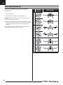
Control Horn and Servo Arm Settings
The table to the right shows the factory settings for the control horns and servo
arms. Fly the aircraft at factory settings before making changes.
NOTICE: If control throws are changed from the recommended settings, the
AR636 gain values may need to be adjusted. Refer to the Spektrum AR636
manual for adjustment of gain values.
After fl ying, you may choose to adjust the linkage positions for the
desired control response. See the lower table.
Horns Arms
Elevator
Rudder
Ailerons
Flaps
More control throw Less control throw
5

EN
Transmitter Setup
IMPORTANT: After you set up your model, always rebind the transmitter and
receiver to set the desired failsafe positions.
Dual Rates
Take fi rst fl ights in Low Rate. For landings use high rate elevator.
NOTICE: To ensure AS3X functions properly, do not lower rate values below
50%. If lower rates are desired, manually adjust the position of the pushrods
on the servo arm.
NOTICE: If oscillation occurs at high speed, refer to the Troubleshooting Guide
for more information.
Expo
Expo is factory set in the receiver. After fi rst fl ights, you may adjust expo in your
transmitter or refer to the AR636 receiver manual for expo adjustment.
Computerized Transmitter Setup
(DX6i, DX6, DX7S, DX8, DX9, DX10t and DX18)
Start all transmitter programming with a blank ACRO model (do a model
reset), then name the model.
Set Dual Rates to:
HIGH 100%
LOW 70%
Set Servo Travel to: 100%
DX6i
1. Go to the SETUP LIST MENU
2. Set MODEL TYPE: ACRO
3. Set REVERSE: Gear Channel
4. Go to ADJUST LIST MENU
5. Set FLAPS: Norm 100 Flap and 0 ELEV ; LAND 80 Flap and
10 ELEV.
DX7S
DX8
1. Go to the SYSTEM SETUP
2. Set MODEL TYPE: AIRPLANE
3. Set WING TYPE: 1 AIL 1 FLAP
4. Go to the FUNCTION LIST
5. Set SERVO SETUP: Reverse GEAR
6. Set FLAP SYSTEM: Choose Flap
NORM: -100% FLAP and 0% ELEV
MID: -30% FLAP and -3% ELEV
LAND: 80% FLAP and -10% ELEV
SPEED 2.0S: SWITCH = FLAP
DX6
DX9
DX10t
DX18
1. Go to the SYSTEM SETUP
2. Set MODEL TYPE: AIRPLANE
3. Set AICRAFT TYPE:
WING: 1 AIL 1 FLAP
4. Go to the FUNCTION LIST
5. Set SERVO SETUP: Reverse GEAR
6. Set FLAP SYSTEM:
SELECT SWITCH D:
POS 0: -100% FLAP and 0% ELEV
POS 1: -30% FLAP and -3% ELEV
POS 2: 80% FLAP and -10% ELEV
SPEED 2.0
6

EN
Binding is the process of programming the receiver to recognize the GUID
(Globally Unique Identifi er) code of a single specifi c transmitter. You need to
‘bind’ your chosen Spektrum
™
DSM2
®
/DSMX
®
technology equipped aircraft
transmitter to the receiver for proper operation.
IMPORTANT: Before binding a transmitter, read the Transmitter Setup section
of this manual to ensure that your transmitter is properly programmed for this
aircraft.
Binding Procedure
IMPORTANT: The included AR636 receiver has been programmed for
operation specifi cally for this aircraft. Refer to the receiver manual for cor-
rect setup if the receiver is replaced or is used in another aircraft.
Read the transmitter instructions for binding to a receiver (location of
transmitter’s Bind control). Please visit www.bindnfl y.com for a com-
plete list of compatible transmitters.
CAUTION: When using a Futaba
®
transmitter with a Spektrum DSM
module, you must reverse the throttle channel and rebind. Refer to your
Spektrum module manual for binding and failsafe instructions. Refer to
your Futaba transmitter manual for instructions on reversing the throttle
channel.
1. Make sure the transmitter is powered off.
2. Move the transmitter controls to neutral (fl ight controls: rudder,
elevators and ailerons) or to low positions (throttle, throttle trim).**
3. Install a bind plug in the receiver bind port extension.
4. Connect the fl ight battery to the ESC. The ESC will produce a series
of sounds. One long tone, then 3 short tones confi rm that the LVC is
set correctly for the ESC. The orange bind LED on the receiver will
begin to fl ash rapidly.
5. Power on the transmitter while holding the transmitter bind button
or switch. Refer to your transmitter’s manual for binding.
6. When the receiver binds to the transmitter, the orange bind light on
the receiver will turn solid and the ESC will produce a series of three
ascending tones. The tones indicate the ESC is armed, provided the
throttle stick and throttle trim are low enough to trigger arming.
7. Remove the bind plug from the bind port extension.
8. Safely store the bind plug (some owners attach the bind plug to their
transmitter using two-part loops and clips).
9. The receiver should retain the binding instructions received from the
transmitter until another binding is done.
* The throttle will not arm if the transmitter’s throttle control is not put at
the lowest position. If you encounter problems, follow the binding instruc-
tions and refer to the transmitter troubleshooting guide for other instruc-
tions. If needed, contact the appropriate Horizon Product Support offi ce.
**Failsafe
If the receiver loses transmitter communication, the failsafe will activate.
When activated, the airplane controls return to the neutral position estab-
lished during step 2 of the binding procedure.
Transmitter and Receiver Binding
The Spektrum AR636 receiver is recommended for ths airplane. If you choose
to install another receiver, ensure that it is at least a 6-channel full range
(sport) receiver. Refer to your receiver manual for correct installation and
operation instructions.
Installation (AR636 shown)
1. Remove the wing from the fuselage.
2. Mount the receiver parallel to the length of the fuselage as shown. Use
double-sided servo tape.
CAUTION: Incorrect installation of the receiver could cause a crash.
3. Attach the appropriate control surfaces to the their respective ports on the
receiver using the chart in the illustration
PNP Receiver Selection and Installation
Bind Plug Installation
BIND PLUG
1 = Throttle
2 = Aileron
3 = Elevator
4 = Rudder
5 = Gear
6 = Flaps
7

EN
Battery Installation and ESC Arming
Battery Selection
We recommend the E-fl ite
®
2200mAh 11.1V 3S 30C Li-Po battery
(EFLB22003S30). Refer to the Optional Parts List for other recommended
batteries. If using a battery other than those listed, the battery should be within
the range of capacity, dimensions and weight of the E-fl ite Li-Po battery packs
to fi t in the fuselage. Be sure the model balances at the recommended CG.
1. Lower the throttle and throttle trim to the lowest settings. Power on the
Transmitter, then wait 5 seconds.
2. Apply hook and loop tape to the bottom of your battery.
3. Push the button (A) into the fuselage and remove the battery hatch.
4. Install the fully charged battery (B) in the battery compartment as shown.
See the Adjusting the Center of Gravity instructions for more information.
5. Make sure the fl ight battery is secured using the hook and loop strap (C).
6. Connect the battery to the ESC (the ESC is now armed).
7. Keep the aircraft immobile and away from wind for 5 seconds or the
system will not initialize.
• The ESC will sound a series of tones (refer to step 6 of the binding
instructions for more information).
• An LED will light on the receiver.
If the ESC sounds a continuous double beep after the fl ight battery is
connected, recharge or replace the battery.
8. Reinstall the battery hatch. Push the rear of the battery hatch securely to
ensure the latch is fully engaged.
A
B
C
8

EN
Center of Gravity (CG)
The CG location is measured from the panel line shown. This CG location
has been determined with the recommended Li-Po battery (EFLB22003S30)
installed in the middle of the battery compartment with landing gear down and
plane inverted.
37mm
Control Direction Tests
Assemble the aircraft and bind your transmitter to the receiver before
performing this test.
After binding a transmitter to the aircraft receiver, set the trims and
sub-trims to 0, then adjust the clevises to center the control surfaces.
Move the controls on the transmitter to make sure the aircraft control
surfaces move in the proper direction.
Transmitter
Command
Aircraft Reaction
Elevator
Up Elevator
Command
Down
Elevator
Command
Aileron
Stick Right
Stick Left
Rudder
Stick Right
Stick Left
Flaps
Half
Full
In front of this panel line.
9

EN
AS3X Control Direction Test
This test ensures that the AS3X control system is functioning properly.
Assemble the aircraft and bind your transmitter to the receiver before
performing this test.
1. Fully lower the throttle.
2. Move the fl ap switch to full fl aps before performing this test.
IMPORTANT: The AR636 programming for this aircraft increases control sur-
face movement when fl aps are fully down.
3. Move the entire aircraft as shown and ensure the control surfaces move in
the direction indicated in the graphic. If the control surfaces do not respond
as shown, do not fl y the aircraft. Refer to the receiver manual for more
information.
Once the AS3X system is active, control surfaces may move rapidly. This is
normal. AS3X is active until the battery is disconnected.
Aircraft
movement
AS3X Reaction
ElevatorAileronRudder
10

EN
Flying Tips and Repairs
Consult local laws and ordinances before choosing a fl ying location.
Range Check your Radio System
Before you fl y, range check the radio system. Refer to your specifi c transmitter
instruction manual for range test information.
Oscillation
Once the AS3X system is active (after advancing the throttle for the fi rst time),
you will normally see the control surfaces react to aircraft movement. In some
fl ight conditions you may see oscillation (the aircraft rocks back and forth on
one axis due to overcontrol). If oscillation occurs, decrease airspeed. If oscilla-
tion persists, refer to the Troubleshooting Guide for more information.
Takeoff
Place the aircraft facing into the wind. Set your transmitter in low rate and
use your fl aps switch to drop the fl aps to takeoff or “half position”. Gradually
increase the throttle to ¾ and steer with the rudder. Flaps make takeoffs
shorter. As the tail comes off the ground, pull back gently on the elevator.
When airborn, fl ip your gear switch to raise your landing gear. Climb to a com-
fortable altitude and then fl ip your fl aps switch to level the fl aps.
Flying
Fly the aircraft and trim it for level fl ight at 3/4 throttle. After landing, adjust the
linkages mechanically to account for trim changes and then reset the trims to
neutral. Ensure the aircraft will fl y straight and level with no trim or sub-trim.
Tip: If using more than 8 clicks of fl ight trim, mechanically adjust the linkage
so less trim is needed, or AS3X operation may be affected.
Landing
For your fi rst fl ights with the recommended battery pack (EFLB22003S30), set
your transmitter timer or a stopwatch to 5 minutes. After fi ve minutes, land the
aircraft. Adjust your timer for longer or shorter fl ights once you have fl own the
model. If at any time the motor pulses, land the aircraft immediately to
recharge the fl ight battery. See the Low Voltage Cutoff (LVC) section for more
details on maximizing battery health and run time.
Land the aircraft into the wind. Use high rate Elevator for landings. Use a small
amount of throttle for the entire descent. Lower the throttle to ¼ and fl ip your
fl aps switch to deploy the fl aps to the landing or “full down position”. Flaps
will make the landing approach steeper and slower, and allow for a
smoother landing. Flip your gear switch to lower your landing gear. This will
slow the aircraft further.
Keep the throttle on until the aircraft is ready to fl are. During fl are, keep the
wings level and the aircraft pointed into the wind. Gently lower the throttle
while pulling back on the elevator to bring the aircraft down on the front
wheels (two point landing). The aircraft can also be landed on all three wheels
(three point landing). When the aircraft touches down, reduce back pressure on
the elevator stick to keep the aircraft from becoming airborn again.
If landing on grass, it is best to hold full up elevator after touchdown and when
taxiing to prevent nosing over.
Once on the ground, avoid sharp turns until the plane has slowed enough to
prevent scraping the wingtips.
NOTICE: If a crash is imminent, reduce the throttle and
trim fully. Failure to do so could result in extra damage
to the airframe, as well as damage to the ESC and
motor.
NOTICE: After any impact, always ensure the receiver
is secure in the fuselage. If you replace the receiver,
install the new receiver in the same orientation as the
original receiver or damage may result.
NOTICE: Crash damage is not covered under warranty.
NOTICE: When you are fi nished fl ying, never leave the aircraft in direct sunlight
or in a hot, enclosed area such as a car. Doing so can damage the foam.
Low Voltage Cutoff (LVC)
When a Li-Po battery is discharged below 3V per cell, it will not hold a charge.
The ESC protects the fl ight battery from over-discharge using Low Voltage
Cutoff (LVC). Before the battery charge decreases too much, LVC removes
power supplied to the motor. Power to the motor pulses, showing that some
battery power is reserved for fl ight control and safe landing.
Disconnect and remove the Li-Po battery from the aircraft after use to prevent
trickle discharge. Charge your Li-Po battery to about half capacity before stor-
age. During storage, make sure the battery charge does not fall below 3V
per cell. LVC does not prevent the battery from over-discharge during storage.
NOTICE: Repeated fl ying to LVC will damage the battery.
Tip: Monitor your aircraft battery’s voltage before and after fl ying by using a
Li-Po Cell Voltage Checker (EFLA111, sold separately).
Repairs
Thanks to the Z-Foam
™
material in this aircraft, repairs to the foam can be
made using virtually any adhesive (hot glue, regular CA, epoxy, etc). When parts
are not repairable, see the Replacement Parts List for ordering by item number.
For a listing of all replacement and optional parts, refer to the list at the end of
this manual.
NOTICE: Use of CA accelerant on your aircraft can damage paint. DO NOT
handle the aircraft until accelerant fully dries.
WARNING:
Always decrease
throttle at propeller
strike.
11

EN
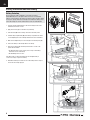
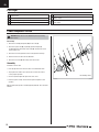
Power Component Service
CAUTION: Always disconnect the fl ight battery before performing
motor service.
Disassembly
1. Remove the screw (A) and spinner (B) from the collet (C).
2. Remove the spinner nut (D), propeller (E), spinner backplate (F),
backplate (G) and collet from the motor shaft (H). You will need a tool to
turn the spinner nut.
3. Remove the 4 screws (I) from the motor mount (J) and the fuselage.
4. Disconnect the motor wires from the ESC wires.
5. Remove the 4 screws (K) and motor (L) from the X-mount.
Assembly
Assemble in reverse order.
• Correctly align and connect the motor wire colors with the ESC wires.
• The propeller size numbers (9.8 x 6) must face out from the motor for
correct propeller operation.
• A tool is required to tighten the spinner nut on the collet.
• Ensure the spinner is fully connected to the spinner backplate for safe
operation.
Tip: For higher fl ying speeds, a 2-bladed propeller (PKZ5101, 10.5 x 9) may be
installed.
D
F
C
G
D
G
C
F
L
B
A
E
E
H
I
K
K
J
Not all wiring shown.
Post Flight
1
Disconnect the fl ight battery from the ESC (Required for Safety
and battery life).
2 Power OFF the transmitter.
3 Remove the fl ight battery from the aircraft.
4 Recharge the fl ight battery.
5 Repair or replace all damaged parts.
6
Store the fl ight battery apart from the aircraft and monitor the
battery charge.
7
Make note of the fl ight conditions and fl ight plan results, planning for
future fl ights.
12

EN
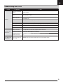
Problem Possible Cause Solution
Oscillation
Flying over recommended
airspeed
Reduce air speed
Damaged propeller or
spinner
Replace propeller or spinner
Imbalanced propeller
Balance the propeller. For more information, view John Redman’s propeller balancing video at www.
horizonhobby.com
Motor vibration Replace parts or correctly align all parts and tighten fasteners as needed
Loose receiver Align and secure receiver in fuselage
Loose aircraft controls Tighten or otherwise secure parts (servo, arm, linkage, horn and control surface)
Worn parts Replace worn parts (especially propeller, spinner or servo)
Irregular servo movement Replace servo
Inconsistent fl ight
performance
Trim is not at neutral If you adjust trim more than 8 clicks, adjust the clevis to remove trim
Sub-Trim is not at neutral No Sub-Trim is allowed. Adjust the servo linkage
Aircraft was not kept im-
mobile for 5 seconds
Power off and on the ESC while keeping the aircraft still for 5 seconds with throttle stick in lowest posi-
tion
Incorrect response
to the AS3X Control
Direction Test
Incorrect direction settings
in the receiver, which can
cause a crash
DO NOT fl y. Correct the direction settings (refer to the receiver manual), then fl y
Troubleshooting Guide AS3X
13

EN
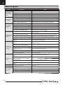
Problem Possible Cause Solution
Aircraft will not re-
spond to throttle but
responds to other
controls
Throttle not at idle and/or throttle trim too high Reset controls with throttle stick and throttle trim at lowest setting
Throttle servo travel is lower than 100% Make sure throttle servo travel is 100% or greater
Throttle channel is reversed Reverse throttle channel on transmitter
Motor disconnected from ESC Make sure motor is connected to the ESC
Extra propeller noise
or extra vibration
Damaged propeller and spinner, collet or motor Replace damaged parts
Propeller is out of balance Balance or replace propeller
Prop nut is too loose Tighten the prop nut
Spinner is not tight or fully seated in place Tighten the spinner or remove the spinner and turn it 180 degrees
Reduced fl ight time
or aircraft under-
powered
Flight battery charge is low Completely recharge fl ight battery
Propeller installed backwards Install propeller with numbers facing forward
Flight battery damaged Replace fl ight battery and follow fl ight battery instructions
Flight conditions may be too cold Make sure battery is warm before use
Battery capacity too low for flight conditions Replace battery or use a larger capacity battery
Aircraft will not Bind
(during binding) to
transmitter
Transmitter too near aircraft during binding process
Move powered transmitter a few feet from aircraft, disconnect and reconnect
fl ight battery to aircraft
Aircraft or transmitter is too close to large metal
object, wireless source or another transmitter
Move aircraft and transmitter to another location and attempt binding again
The bind plug is not installed correctly in the bind port Install bind plug in bind port and bind the aircraft to the transmitter
Flight battery/transmitter battery charge is too low Replace/recharge batteries
Bind switch or button not held long enough during
bind process
Power off transmitter and repeat bind process. Hold transmitter bind
button or switch until receiver is bound
Aircraft will not con-
nect (after binding)
to transmitter
Transmitter too near aircraft during connecting
process
Move powered transmitter a few feet from aircraft, disconnect and reconnect
fl ight battery to aircraft
Aircraft or transmitter is too close to large metal
object, wireless source or another transmitter
Move aircraft and transmitter to another location and attempt connecting again
Bind plug left installed in bind port Rebind transmitter to the aircraft and remove the bind plug before cycling power
Aircraft bound to different model memory
(ModelMatch
TM
radios only)
Select correct model memory on transmitter
Flight battery/Transmitter battery charge is too low Replace/recharge batteries
Transmitter may have been bound to a different air-
craft using different DSM protocol
Bind aircraft to transmitter
Control surface does
not move
Control surface, control horn, linkage or servo
damage
Replace or repair damaged parts and adjust controls
Wire damaged or connections loose Do a check of wires and connections, connect or replace as needed
Transmitter is not bound correctly or the incorrect
airplanes was selected
Re-bind or select correct airplanes in transmitter
Flight battery charge is low Fully recharge fl ight battery
BEC (Battery Elimination Circuit) of the ESC is
damaged
Replace ESC
Controls reversed Transmitter settings are reversed
Perform the Control Direction Test and adjust the controls on transmitter
appropriately
Motor power pulses
then motor loses
power
ESC uses default soft Low Voltage Cutoff (LVC) Recharge fl ight battery or replace battery that is no longer performing
Weather conditions might be too cold Postpone flight until weather is warmer
Battery is old, worn out, or damaged Replace battery
Battery C rating might be too small Use recommended battery
Troubleshooting Guide
14

EN
AMA National Model Aircraft Safety Code
Please see your local or regional modeling association’s guidelines for proper, safe
operation of your model aircraft.
Effective January 1, 2014
A. GENERAL
A model aircraft is a non-human-carrying aircraft capable of sustained fl ight
in the atmosphere. It may not exceed limitations of this code and is intended
exclusively for sport, recreation, education and/or competition. All model fl ights
must be conducted in accordance with this safety code and any additional
rules specifi c to the fl ying site.
1. Model aircraft will not be fl own:
(a) In a careless or reckless manner.
(b) At a location where model aircraft activities are prohibited.
2. Model aircraft pilots will:
(a) Yield the right of way to all man carrying aircraft.
(b) See and avoid all aircraft and a spotter must be used when appropriate.
(AMA Document #540-D.)
(c) Not fl y higher than approximately 400 feet above ground level within
three (3) miles of an airport, without notifying the airport operator.
(d) Not interfere with operations and traffi c patterns at any airport, heliport
or seaplane base except where there is a mixed use agreement.
(e) Not exceed a takeoff weight, including fuel, of 55 pounds unless in
compliance with the AMA Large Model Aircraft program. (AMA
Document 520-A.)
(f) Ensure the aircraft is identifi ed with the name and address or AMA
number of the owner on the inside or affi xed to the outside of the
model aircraft. (This does not apply to model aircraft fl own indoors).
(g) Not operate aircraft with metal-blade propellers or with gaseous boosts
except for helicopters operated under the provisions of AMA Document
#555.
(h) Not operate model aircraft while under the infl uence of alcohol or while
using any drug which could adversely affect the pilot’s ability to safely
control the model.
(i) Not operate model aircraft carrying pyrotechnic devices which explode
or burn, or any device which propels a projectile or drops any object
that creates a hazard to persons or property.
Exceptions:
• Free Flight fuses or devices that burn producing smoke and are
securely attached to the model aircraft during fl ight.
• Rocket motors (using solid propellant) up to a G-series size may
be used provided they remain attached to the model during fl ight.
Model rockets may be fl own in accordance with the National
Model Rocketry Safety Code but may not be launched from
model aircraft.
• Offi cially designated AMA Air Show Teams (AST) are authorized to
use devices and practices as defi ned within the Team AMA
Program Document (AMA Document #718).
(j) Not operate a turbine-powered aircraft, unless in compliance with the
AMA turbine regulations. (AMA Document #510-A).
3. Model aircraft will not be fl own in AMA sanctioned events, air shows or
model demonstrations unless:
(a) The aircraft, control system and pilot skills have successfully
demonstrated all maneuvers intended or anticipated prior to the
specifi c event.
(b) An inexperienced pilot is assisted by an experienced pilot.
4. When and where required by rule, helmets must be properly worn and
fastened. They must be OSHA, DOT, ANSI, SNELL or NOCSAE approved or
comply with comparable standards.
B. RADIO CONTROL
1. All pilots shall avoid fl ying directly over unprotected people, vessels,
vehicles or structures and shall avoid endangerment of life and property
of others.
2. A successful radio equipment ground-range check in accordance with
manufacturer’s recommendations will be completed before the fi rst fl ight
of a new or repaired model aircraft.
3. At all fl ying sites a safety line(s) must be established in front of which all
fl ying takes place (AMA Document #706.)
(a) Only personnel associated with fl ying the model aircraft are allowed at
or in front of the safety line.
(b) At air shows or demonstrations, a straight safety line must be
established.
(c) An area away from the safety line must be maintained for spectators.
(d) Intentional fl ying behind the safety line is prohibited.
4. RC model aircraft must use the radio-control frequencies currently allowed
by the Federal Communications Commission (FCC). Only individuals
properly licensed by the FCC are authorized to operate equipment on
Amateur Band frequencies.
5. RC model aircraft will not operate within three (3) miles of any pre-existing
fl ying site without a frequency-management agreement (AMA Documents
#922 and #923.)
6. With the exception of events fl own under offi cial AMA Competition
Regulations, excluding takeoff and landing, no powered model may be
fl own outdoors closer than 25 feet to any individual, except for the pilot
and the pilot’s helper(s) located at the fl ight line.
7. Under no circumstances may a pilot or other person touch a model aircraft
in fl ight while it is still under power, except to divert it from striking an
individual.
8. RC night fl ying requires a lighting system providing the pilot with a clear
view of the model’s attitude and orientation at all times. Hand-held illumi-
nation systems are inadequate for night fl ying operations.
9. The pilot of a RC model aircraft shall:
(a) Maintain control during the entire fl ight, maintaining visual contact
without enhancement other than by corrective lenses prescribed for
the pilot.
(b) Fly using the assistance of a camera or First-Person View (FPV) only
in accordance with the procedures outlined in AMA Document #550.
(C) Fly using the assistance of autopilot or stabilization system only in
accordance with the procedures outlined in AMA Document #560.
15

EN
Limited Warranty
What this Warranty Covers
Horizon Hobby, LLC, (Horizon) warrants to the original purchaser that the
product purchased (the “Product”) will be free from defects in materials and
workmanship at the date of purchase.
What is Not Covered
This warranty is not transferable and does not cover (i) cosmetic damage,
(ii) damage due to acts of God, accident, misuse, abuse, negligence,
commercial use, or due to improper use, installation, operation or
maintenance, (iii) modifi cation of or to any part of the Product, (iv) attempted
service by anyone other than a Horizon Hobby authorized service center, (v)
Product not purchased from an authorized Horizon dealer, or (vi) Product not
compliant with applicable technical regulations.
OTHER THAN THE EXPRESS WARRANTY ABOVE, HORIZON MAKES NO OTHER
WARRANTY OR REPRESENTATION, AND HEREBY DISCLAIMS ANY AND ALL
IMPLIED WARRANTIES, INCLUDING, WITHOUT LIMITATION, THE IMPLIED
WARRANTIES OF NON-INFRINGEMENT, MERCHANTABILITY AND FITNESS
FOR A PARTICULAR PURPOSE. THE PURCHASER ACKNOWLEDGES THAT THEY
ALONE HAVE DETERMINED THAT THE PRODUCT WILL SUITABLY MEET THE
REQUIREMENTS OF THE PURCHASER’S INTENDED USE.
Purchaser’s Remedy
Horizon’s sole obligation and purchaser’s sole and exclusive remedy shall be
that Horizon will, at its option, either (i) service, or (ii) replace, any Product
determined by Horizon to be defective. Horizon reserves the right to inspect
any and all Product(s) involved in a warranty claim. Service or replacement
decisions are at the sole discretion of Horizon. Proof of purchase is required
for all warranty claims. SERVICE OR REPLACEMENT AS PROVIDED UNDER
THIS WARRANTY IS THE PURCHASER’S SOLE AND EXCLUSIVE REMEDY.
Limitation of Liability
HORIZON SHALL NOT BE LIABLE FOR SPECIAL, INDIRECT, INCIDENTAL
OR CONSEQUENTIAL DAMAGES, LOSS OF PROFITS OR PRODUCTION OR
COMMERCIAL LOSS IN ANY WAY, REGARDLESS OF WHETHER SUCH CLAIM IS
BASED IN CONTRACT, WARRANTY, TORT, NEGLIGENCE, STRICT LIABILITY OR
ANY OTHER THEORY OF LIABILITY, EVEN IF HORIZON HAS BEEN ADVISED OF
THE POSSIBILITY OF SUCH DAMAGES. Further, in no event shall the liability
of Horizon exceed the individual price of the Product on which liability
is asserted. As Horizon has no control over use, setup, fi nal assembly,
modifi cation or misuse, no liability shall be assumed nor accepted for any
resulting damage or injury. By the act of use, setup or assembly, the user
accepts all resulting liability. If you as the purchaser or user are not prepared
to accept the liability associated with the use of the Product, purchaser is
advised to return the Product immediately in new and unused condition to
the place of purchase.
Law
These terms are governed by Illinois law (without regard to confl ict of law
principals). This warranty gives you specifi c legal rights, and you may also
have other rights which vary from state to state. Horizon reserves the right
to change or modify this warranty at any time without notice.
WARRANTY SERVICES
Questions, Assistance, and Services
Your local hobby store and/or place of purchase cannot provide warranty
support or service. Once assembly, setup or use of the Product has been
started, you must contact your local distributor or Horizon directly. This will
enable Horizon to better answer your questions and service you in the event
that you may need any assistance. For questions or assistance, please visit
our website at www.horizonhobby.com, submit a Product Support Inquiry, or
call the toll free telephone number referenced in the Warranty and Service
Contact Information section to speak with a Product Support representative.
Inspection or Services
If this Product needs to be inspected or serviced and is compliant in the
country you live and use the Product in, please use the Horizon Online
Service Request submission process found on our website or call Horizon to
obtain a Return Merchandise Authorization (RMA) number. Pack the Product
securely using a shipping carton. Please note that original boxes may be
included, but are not designed to withstand the rigors of shipping without
additional protection. Ship via a carrier that provides tracking and insurance
for lost or damaged parcels, as Horizon is not responsible for merchandise
until it arrives and is accepted at our facility. An Online Service Request is
available at http://www.horizonhobby.com/content/_service-center_render-
service-center. If you do not have internet access, please contact Horizon
Product Support to obtain a RMA number along with instructions for
submitting your product for service. When calling Horizon, you will be asked
to provide your complete name, street address, email address and phone
number where you can be reached during business hours. When sending
product into Horizon, please include your RMA number, a list of the included
items, and a brief summary of the problem. A copy of your original sales
receipt must be included for warranty consideration. Be sure your name,
address, and RMA number are clearly written on the outside of the shipping
carton.
NOTICE: Do not ship LiPo batteries to Horizon. If you have any issue
with a LiPo battery, please contact the appropriate Horizon Product
Support offi ce.
Warranty Requirements
For Warranty consideration, you must include your original sales
receipt verifying the proof-of-purchase date. Provided warranty
conditions have been met, your Product will be serviced or replaced free
of charge. Service or replacement decisions are at the sole discretion of
Horizon.
Non-Warranty Service
Should your service not be covered by warranty, service will be
completed and payment will be required without notifi cation or
estimate of the expense unless the expense exceeds 50% of the retail
purchase cost. By submitting the item for service you are agreeing to
payment of the service without notifi cation. Service estimates are available
upon request. You must include this request with your item submitted for
service. Non-warranty service estimates will be billed a minimum of ½ hour
of labor. In addition you will be billed for return freight. Horizon accepts
money orders and cashier’s checks, as well as Visa, MasterCard, American
Express, and Discover cards. By submitting any item to Horizon for service,
you are agreeing to Horizon’s Terms and Conditions found on our website
http://www.horizonhobby.com/content/_service-center_render-service-
center.
ATTENTION: Horizon service is limited to Product compliant in the
country of use and ownership. If received, a non-compliant Product will
not be serviced. Further, the sender will be responsible for arranging
return shipment of the un-serviced Product, through a carrier of the
sender’s choice and at the sender’s expense. Horizon will hold non-
compliant Product for a period of 60 days from notifi cation, after which
it will be discarded.
16

EN
Declaration of Conformity
(in accordance with ISO/IEC 17050-1)
No. HH2014070901
Product(s): E-fl ite P-51D Mustang BNF Basic
Item Number(s): EFL6750
Equipment class: 1
The object of declaration described above is in conformity with the require-
ments of the specifi cations listed below, following the provisions of the Euro-
pean R&TTE directive 1999/5/EC and EMC Directive 2004/108/EC:
EN301 489-1 V1.9.2: 2012
EN301 489-17 V2.1.1: 2009
EN55022:2010 + AC:2011
EN55024:2010
Signed for and on behalf of:
Horizon Hobby, LLC.
Champaign, IL USA
July 9, 2014
Declaration of Conformity
(in accordance with ISO/IEC 17050-1)
No. HH2014070902
Product(s): E-fl ite P-51D Mustang PNP
Item Number(s): EFL6775
Equipment class: 1
The object of declaration described above is in conformity with the require-
ments of the specifi cations listed below, following the provisions of the EMC
Directive 2004/108/EC:
EN55022:2010 + AC:2011
EN55024:2010
Signed for and on behalf of:
Horizon Hobby, LLC.
Champaign, IL USA
July 9, 2014
Compliance Information for the European Union
Contact Information
Country of Purchase Horizon Hobby Phone Number/Email Address Address
United States of
America
Horizon Service Center
(Repairs and Repair Requests)
servicecenter.horizonhobby.com/
RequestForm/
4105 Fieldstone Rd
Champaign, Illinois, 61822 USA
Horizon Product Support
(Product Technical Assistance)
www.quickbase.com/db/
bghj7ey8c?a=GenNewRecord
888-959-2305
Sales
sales@horizonhobby.com
888-959-2305
United Kingdom
Service/Parts/Sales:
Horizon Hobby Limited
sales@horizonhobby.co.uk
Units 1–4 , Ployters Rd, Staple Tye
Harlow, Essex, CM18 7NS, United Kingdom
+44 (0) 1279 641 097
Germany
Horizon Technischer Service service@horizonhobby.de
Christian-Junge-Straße 1
25337 Elmshorn, Germany
Sales: Horizon Hobby GmbH +49 (0) 4121 2655 100
France
Service/Parts/Sales:
Horizon Hobby SAS
infofrance@horizonhobby.com 11 Rue Georges Charpak
77127 Lieusaint, France
+33 (0) 1 60 18 34 90
China
Service/Parts/Sales:
Horizon Hobby – China
info@horizonhobby.com.cn Room 506, No. 97 Changshou Rd.
Shanghai, China 200060
+86 (021) 5180 9868
FCC Information
Operation is subject to the following two conditions: (1) This device may not cause
harmful interference, and (2) this device must accept any interference received, including
interference that may cause undesired operation.
CAUTION: Changes or modifi cations not expressly approved by the party
responsible for compliance could void the user’s authority to operate the
equipment.
This product contains a radio transmitter with wireless technology which has been tested
and found to be compliant with the applicable regulations governing a radio transmitter
in the 2.400GHz to 2.4835GHz frequency range.
Instructions for disposal of WEEE by users in the European Union
This product must not be disposed of with other waste. Instead, it is the user’s responsibility to dispose of their waste equipment by handing it over
to a designated collections point for the recycling of waste electrical and electronic equipment. The separate collection and recycling of your waste
equipment at the time of disposal will help to conserve natural resources and ensure that it is recycled in a manner that protects human health and
the environment. For more information about where you can drop off your waste equipment for recycling, please contact your local city offi ce, your
household waste disposal service or where you purchased the product.
Robert Peak
Chief Financial Offi cer
Horizon Hobby, LLC
Robert Peak
Chief Financial Offi cer
Horizon Hobby, LLC
IC Information
This device complies with Industry Canada licence-exempt RSS standard(s).
Operation is subject to the following two conditions: (1) this device may not
cause interference, and (2) this device must accept any interference, including
interference that may cause undesired operation of the device.
17

Dichiarazione di conformità
(in conformità con ISO/IEC 17050-1))
No. HH2014070901
Prodotto(i): E-fl ite P-51D Mustang BNF Basic
Codice componente: EFL6750
Classe dei dispositivi: 1
L’oggetto della dichiarazione di cui sopra è conforme ai requisiti delle
specifi che elencate qui di seguito, secondo le disposizioni delle direttive
europee R&TTE 1999/5/EC e EMC 2004/108/EC:
EN301 489-1 V1.9.2: 2012
EN301 489-17 V2.1.1: 2009
EN55022:2010 + AC:2011
EN55024:2010
Firmato a nome e per conto di:
Horizon Hobby LLC.
Champaign IL USA
9 luglio 2014
Dichiarazione di conformità
(in conformità con ISO/IEC 17050-1))
No. HH2014070902
Prodotto(i): E-fl ite P-51D Mustang PNP
Codice componente: EFL6775
Classe dei dispositivi: 1
L’oggetto della dichiarazione di cui sopra è conforme ai requisiti delle
specifi che elencate qui di seguito, secondo le disposizioni della direttiva
europea EMC 2004/108/EC:
EN55022:2010 + AC:2011
EN55024:2010
Firmato a nome e per conto di:
Horizon Hobby LLC.
Champaign IL USA
9 luglio 2014
Informazioni sulla conformità per l’Unione Europea
Istruzioni per lo smaltimento RAEE da parte degli utenti dell’Unione Europea
Questo prodotto non deve essere smaltito assieme ai rifi uti domestici. Al contrario, l’utente è responsabile dello smaltimento di tali rifi uti, che devono
essere portati in un centro di raccolta designato per il riciclaggio di rifi uti elettrici e apparecchiature elettroniche. La raccolta differenziata e il riciclag-
gio di tali rifi uti provenienti da apparecchiature, nel momento dello smaltimento aiuteranno a preservare le risorse naturali e garantiranno un riciclag-
gio adatto a proteggere il benessere dell’uomo e dell’ambiente. Per maggiori informazioni sui centri di raccolta, contattare il proprio uffi cio locale, il
servizio di smaltimento rifi uti o il negozio presso il quale è stato acquistato il prodotto.
Robert Peak
Chief Financial Offi cer
Horizon Hobby, LLC
Robert Peak
Chief Financial Offi cer
Horizon Hobby, LLC
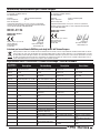
Part # | Nummer
Numéro | Codice
Description Beschreibung Description Descrizione
EFLG185R
85° Main Retract
Replacement: P-51D
E-fl ite P-51D: 85° Ersatzfw.
Train rentrant principal 85° de
remplacement
Ricambio retrattile principale 85°:
P-51D
EFL6705
Mains 65mm & Tail 28m Wheel:
P-51D
E-fl ite P-51D: Fahrwerksräder u.
Spornrad
Train rentrant principal 85° de
remplacement
Ruote principali 65mm e di coda
28mm: P-51D
EFL6703
Main Landing Gear Wires & Cov-
ers: P-51D
E-fl ite P-51D: Fahrwerksdrähte u.
Abdeckungen
Train rentrant principal 85° de
remplacement
Fili e copertura carrello princi-
pale: P-51D
EFL6720
Painted Wing with Scoop: P-51D E-fl ite P-51D: Tragfl äche lackiert Aile peinte avec prise d’air
Ala verniciata con presa d’aria:
P-51D
EFL6767
Painted Fuselage: P-51D E-fl ite P-51D: Rumpf o. Einbauten Fuselage peint Fusoliera verniciata: P-51D
EFL6725
Horizontal Stabilizer: P-51D E-fl ite P-51D: Höhenleitwerk Stabilisateur Stabilizzatore orizzontale: P-51D
EFL6712
Battery Hatch: P-51D E-fl ite P-51D: Akkuklappe Trappe à batterie Coperchio batteria: P-51D
EFL6701
4 Blade Spinner 71mm: P-51D
E-fl ite P-51D: 4-Blatt Spinner
71mm
Cône quadripale 71mm Ogiva 4 pale: P-51D
EFL6726
Cowling & Exhaust: P-51D
E-fl ite P-51D: Motorhaube u.
Auspuffanlage
Capot avec fausses sorties
d’échappement
Capottina motore e scarico:
P-51D
EFL6722
Pushrods & Control Horn Set:
P-51D
E-fl ite P-51D: Ruderhorn u. Anlen-
kungen
Set de tringleries Set rinvii e squadrette: P-51D
EFL6713
Canopy and Pilot: P-51D
E-fl ite P-51D: Kabinenhaube u.
Pilot
Verrière avec pilote Capottina e pilota: P-51D
EFL6702
Decal Sheet: P-51D E-fl ite P-51D: Dekorbogen Planche de décoration Foglio adesivi: P-51D
EFL6728
Motor Mount: P-51D E-fl ite P-51D: Motorhalter Support moteur Supporto motore: P-51D
EFL6704
Prop Adapter: P-51D E-fl ite P-51D: Propelleradapter Adaptateur d’hélice Adattatore elica: P-51D
EFL6735
Servo Wire Tape: P-51D E-fl ite P-51D: Servokabeltape Masquage de câbles des servos Nastro per fi lo servo: P-51D
EFLA1030B
30-Amp Pro SB Brushless ESC
E-fl ite 30-Amp Pro Switch-Mode
BEC Brushless Regler (V2)
Contrôleur brushless 30A 30-Amp Pro SB Brushless ESC
EFLP98604E
Propeller 9.8x6 - 4 Blade E-fl ite Propeller 9.8x6 - 4 Blatt Hélice quadripale 9.8x6 Elica 9.8x6 - 4 pale
PKZ1081
SV80 Long Lead 3-Wire Servo
Parkzone SV80 Servo mit langem
Kabel
Servo 3 câbles grande longueur
SV80
SV80 servo a 3 fi li a terminale
lungo
PKZ1090
DSV130 digital, metal gear DSV130 Digitalservo MG DSV130 digital, pignons métal
DSV130 digitale, ingranaggi in
metallo
PKZ5116
15 BL Outrunner motor, 950Kv
15BL Außenläufer 950Kv: Extra
300
Moteur brushless à cage tournante
15, 950kV
15 BL motore cassa rotante;
950KV
Replacement Parts • Ersatzteile • Pièces de rechange • Pezzi di ricambio
62

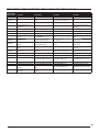
Part # | Nummer
Numéro | Codice
Description Beschreibung Description Descrizione
PKZ5101 Propeller: 10.5 x 9: Extra 300 Propeller: 10.5 x 9: Extra 300 Hélice 10.5 x 9: Extra 300 Elica: 10.5 x 9: Extra 300
EFLA250
Park Flyer Tool Assortment,
5 pc
E-fl ite Park Flyer Werkzeugsortiment;
5 teilig
Assortiment d’outils park fl iyer, 5pc
Park Flyer assortimento attrezzi,
5 pc
EFLAEC302 EC3 Battery Connector, Female (2) EC3 Akkukabel, Buchse (2) Prise EC3 femelle (2pc) EC3 Connettore femmina x batteria (2)
EFLAEC303
EC3 Device/Battery Connector,
Male/Female
EC3 Kabelsatz, Stecker/Buchse Prise EC3 male/femelle
EC3 Connettore batteria maschio/
femmina
EFLA111 Li-Po Cell Voltage Checker Li-Po Cell Voltage Checker Testeur de tension d’éléments Li-Po Voltmetro verifi ca batterie LiPo
EFLB22003S30 11.1V 3S 30C 2200MAH Li-Po 11.1V 3S 30C 2200mAh LiPo 11.1V 3S 30C 2200MAH Li-Po 11.1V 3S 30C 2200MAH Li-Po
PKZ1029 11.1V 3S 25C 2200MAH Li-Po 11.1V 3S 25C 2200mAh LiPo 11.1V 3S 25C 2200MAH Li-Po 11.1V 3S 25C 2200MAH Li-Po
DYNC2010CA
Prophet Sport Plus 50W AC DC
Charger
Dynamite Ladegerät Prophet Sport
Plus 50W AC/DC EU
Chargeur Prophet Sport Plus 50W AC
DC
Caricabatterie Prophet Sport Plus 50W
AC DC
SPMA3080
AS3X Programming Cable - Audio
Interface
Spektrum Audio-Interface AS3X
Empfänger Programmierkabel
Câble de programmation audio AS3X
pour smartphone
Cavo di programmazione AS3X -
Interfaccia audio
SPMA3065
AS3X Programming Cable - USB
Interface
Spektrum USB-Interface AS3X Emp-
fänger Programmierkabel
Câble de programmation USB AS3X
pour PC
Cavo di programmazione AS3X -
Interfaccia USB
DYN1405
Li-Po Charge Protection Bag,
Large
Dynamite LiPoCharge Protection Bag
groß
Sac de charge Li-Po, grand modèle
Sacchetto grande di protezione per
carica LiPo
DYN1400
Li-Po Charge Protection Bag,
Small
Dynamite LiPoCharge Protection
Bag klein
Sac de charge Li-Po, petit modèle Busta protezione piccola par LiPo
DX6i DSMX 6-Channel Transmitter Spektrum DX6i DSMX 6-Kanal Sender Emetteur DX6i DSMX 6 voies DX6i DSMX Trasmettitore 6 canali
DX6 DSMX 6-Channel Transmitter Spektrum DX6 DSMX 6-Kanal Sender Emetteur DX6 DSMX 6 voies DX6 DSMX Trasmettitore 6 canali
DX7s DSMX 7-Channel Transmit-
ter
Spektrum DX7s DSMX 7 Kanal Sender Emetteur DX7s DSMX 7 voies DX7s DSMX Trasmettitore 7 canali
DX8 DSMX 8-Channel Transmitter Spektrum DX8 DSMX 8 Kanal Sender Emetteur DX8 DSMX 8 voies DX8 DSMX Trasmettitore 8 canali
DX9 DSMX 9-Channel Transmitter Spektrum DX9 DSMX 9 Kanal Sender Emetteur DX9 DSMX 9 voies DX9 DSMX Trasmettitore 9 canali
DX10t DSMX 10-Channel
Transmitter
Spektrum DX10t DSMX 10 Kanal
Sender
Emetteur DX10t DSMX 10 voies DX10t DSMX Trasmettitore 10 canali
DX18 DSMX 18-Channel
Transmitter
Spektrum DX18 DSMX 18 Kanal
Sender
Emetteur DX18 DSMX 18 voies DX18 DSMX Trasmettitore 18 canali
Optional Parts • Optionale Bauteile • Pièces optionnelles • Pezzi opzionali
63

© 2014 Horizon Hobby, LLC.
E-fl ite, AS3X, Prophet, EC3, DSM, DSM2, DSMX, the DSMX logo, Z-Foam, Bind-N-Fly, the BNF logo,
Plug-N-Play and ModelMatch are trademarks or registered trademarks of Horizon Hobby, LLC.
The Spektrum trademark is used with permission of Bachmann Industries, Inc.
Futaba is a registered trademark of Futaba Denshi Kogyo Kabushiki Kaisha Corporation of Japan.
All other trademarks, service marks and logos are property of their respective owners.
Patents pending.
http://www.e-fl iterc.com/
EFL6750, EFL6775
Created 04/15
41187.1
-
 1
1
-
 2
2
-
 3
3
-
 4
4
-
 5
5
-
 6
6
-
 7
7
-
 8
8
-
 9
9
-
 10
10
-
 11
11
-
 12
12
-
 13
13
-
 14
14
-
 15
15
-
 16
16
-
 17
17
-
 18
18
-
 19
19
-
 20
20


E-flite P-51D Mustang Manuale utente
- Categoria
- Giocattoli telecomandati
- Tipo
- Manuale utente
in altre lingue
- English: E-flite P-51D Mustang User manual
Documenti correlati
-
E-flite EFLU3550 Manuale del proprietario
-
-
-
E-flite EFL01150 Manuale del proprietario
-
-
-
E-flite Carbon-Z Cub Manuale utente
-
-
-
Altri documenti
-
Horizon Hobby UMX YAK 54 3D Manuale utente
-
ParkZone PKZ5275 Manuale del proprietario
-
-
-
Dynamite DYNC2030 Manuale del proprietario
-
HobbyZone HBZ6150 Manuale utente
-
 Hangar 9 HANGAR 9 Ultra Stick 30cc Manuale del proprietario
-
 RC Logger RC EYE One S Manuale utente
-
Spektrum S1200 Manuale del proprietario
-
 Hangar 9 HAN2345 Manuale del proprietario


