
,6758=,21,'¶862(',,167$//$=,21(
,167$//$7,21$1'86(5¶60$18$/
;3$66%&
;3$66%&
',668$625($8720$7,&2
$8720$7,&%2//$5'
Attenzione! Leggere attentamente le “Avvertenze” all’interno! Caution! Read “Warnings” inside carefully! Attention! Veuillez lire attentivement les Avertissements qui se trouvent à l’intérieur!
Achtung! Bitte lesen Sie aufmerksam die „Hinweise“ im Inneren! ¡Atención¡ Leer atentamente las “Advertencias” en el interior! Let op! Lees de “Waarschuwingen” aan de binnenkant zorgvuldig!
D812186 00550_004 13-06-14

- 3 -
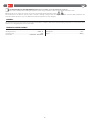
The INSTALLATION, USE AND MAINTENANCE handbook is for installers, users and maintenance engineers.
Please read it carefully before installing the appliance, before using it and before routine or extraordinary maintenance work.
Operations that, if not carried out correctly, can be risky, are indicated with the following symbols :
The manufacturer is not liable for injury to people or animals or damage to things in the case of applications that exceed the limits speci ed on the
enclosed technical data sheet or by a use di erent from what the appliance has been designed.
GENERAL
The deterrent bollard is the ideal solution for managing vehicle tra c in compliance with modern urban furnishing requirements. It can be used to contol
entrances or to safeguard private areas in total safety.
TECHNICAL SPECIFICATIONS
Working temp................................................................................................-40 +60 °C
Working time...............................................................................................................6,5 s.
Weight.........................................................................................................................260 kg
EN
Power..................................................................230 Vac ± 10% ; 50÷60 Hz; 500 W
Working frequency.......................................................................................3.000 / 24
Protection level...........................................................................................................IP67
Control unit......................................................................PERSEO CBD / PERSEO CBE

- 4 -
2
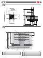
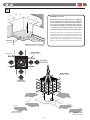
DISPOSIZIONE • LAYOUT
A Asfalto - Road surface
B Cemento RcK25 - Cement RcK25
C Guaina Ø50 - Sheathing Ø50
D Allacciamento alla rete fognaria Ø100 - Connection to the sewer network Ø100
E Sabbia ne - Fine sand
F Ghiaia - Pebble gravel
G Ø20 Fe B44K (non forniti • not provided)
DIMENSIONI D’INGOMBRO • OVERALL SIZE DIMENSIONS
1
D
F
F
E
B
C
A
G
1400
1140
900
200
280
60
1000 ÷ 1200
560
280
1064
1140 800
Ø102
1000 ÷ 1200
560
280
Ø273 x 10
Ø20 Fe B44k
(non forniti • not provided)
IT EN

- 5 -
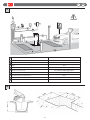
3
NOTA CAVI • WIRING NOTE
3
1500
1500
FONDAZIONE • FOUNDATION
4
1400
ENIT
1
Linea M
onofase - Single-phase line H05VV 2 x 1,5 + T
2
R
icevitore - Receiver 4 x 0,5
3
SOS 4 x 0,5
4
Lampe 2 x 0,5
5
Selettore a chiave - Key selector 2 x 0,5
6
XPASS B 800C / XPASS B 800C SD Cavo in dotazione /
Cable supplied by us
7
Rivelatore magnetico - Detector-Request istruction Cavo intrecciato / Twisted cable
8
Fotocellula trasmettitore - Trasmitter photocell 2 x 0,5
9
Fotocellula ricevitore - Receiver photocell 4 x 0,5
10
Semaforo - Tra c light 3 x 0,5 + T

- 6 -
Pump unit
RUNNING
DIRECTION
RUNNING
DIRECTION
INSTALLAZIONE DISSUASORE • INSTALL BOLLARD
Allacciamento alla rete fognaria
Connection to the sewer network
5
Senso di marcia
Running direction
Senso di marcia
Running direction
1140
Sabbia ne
Fine sand
DRENAGGIO • DRAINAGE
Assicurarsi che il terreno abbia un buon assorbimento
d’acqua immettendo circa 40 litri d’acqua e veri cando
che lo svuotamento avvenga in meno di 30 minuti; in
caso contrario realizzare il drenaggio delle acque tra-
mite tubazioni da collegare ad ogni singola cassaforma
e raccordate alla rete fognaria con sifone, oppure ad un
pozzetto dotato di un sistema di svuotamento dell’acqua.
Ensure that the soil has a adequate water absorption by
entering about 40 liters of water and checking that the em-
ptying takes place in less than 30 minutes; otherwise realize
the drainage of water through pipes connected to every
single manhole and connected to the sewage network with
siphon, or a collecting sump with a drainage system of water.
Ø20 Fe B44k
(non forniti • not provided)
Ø20 F
e B44k
(non forniti • not provided)
IT EN

- 7 -
~ 250
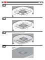
COMPLETARE LA PAVIMENTAZIONE • FLOORING COMPLETION
POSARE LA RETE ELETTROSALDATA • LAY THE ELECTROWELDED MESH
RIEMPIRE DI SABBIA FINO A ~250 MM DAL PIANO STRADALE • FILL WITH SAND TO ~250 MM FROM THE ROAD SURFACE
LIVELLARE COL PIANO STRADALE • LEVEL WITH THE ROAD SURFACE
9
8
7
6
ENIT

- 8 -
MOTA
GND
COM
MOTB
EV
EV
M
24 Vac
LED
BZ
BZ
FCA
COM
FCC
COM
nero / black
gialloverde / yellowgreen
marrone / brown
blu / blue
bianco / white
bianco / white
giallo / yellow
giallo / yellow
verde / green
verde / green
arancione / orange
arancione / orange
N.C.
rosa / pink
rosso / red
rosso / red
rosa / pink
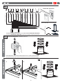
COLLEGAMENTI ELETTRICI • ELECTRICAL CONNECTIONS
10
SBLOCCO DI EMERGENZA • EMERGENCY RELEASE
11
1
2
Interrompendo l’alimentazione elettrica il dissuasore scende spontaneamente.
The deterrent bollard lowers spontaneously when you disconnect the power supply.
Sensore stelo alto • Sensor stem high
IT EN
XPASS B 800CXPASS B 800C SD
PERSEO CBD / PERSEO CBE
Consultare il manuale d’installazione e uso della centralina PERSEO CBD / PERSEO CBE.
Consult the PERSEO CBD / PERSEO CBE control unit’s installation and operating manual.

- 9 -
GENERAL SAFETY
• For safety reasons and to comply with current standards, we recommend using the control unit.
• The construction components of this product must comply with the following European Directives: 2004/108/CEE, 2006/108/EEC, 2006/42 EEC and subsequent
amendments. As for all non-EEC countries, the above-mentioned standards as well as the current national standards should be respected in order to achieve
a good safety level.
• The Company declines all responsibility for any consequences resulting from failure to observe Good Technical Practice when installing the device described
in the present manual.
• Do not install the product in potentially explosive atmosphere or wherever there is a re risk.
• Disconnect the electrical supply before carrying out any work on the installation. Also disconnect any bu er batteries, if tted.
• Fit an omnipolar or magnetothermal switch on the mains power supply, having a contact opening distance equal to or greater than 3,5 mm. Also t an adequate
cut-out device for the bu er batteries.
• Check that a di erential switch with a 0.03A threshold is tted just before the power supply mains.
• Check that earthing is carried out correctly.
• Installation must be carried out using the safety devices and controls prescribed by the EN 12978 Standard.
• Fit all the safety devices (photocells, electric edges etc.) which are needed to protect the area from any danger caused by squashing, conveying.
• Position at least one luminous signal indication device (blinker) where it can be easily seen, and x a Warning sign next to the structure.
• Only use original parts for any maintenance or repair operation. The Company declines all responsibility with respect to the automation safety and correct
operation when other producers’ components are used.
• Do not modify the automation components, unless explicitly authorised by the Company.
• Scrap packing materials (plastic, cardboard, polystyrene etc) according to the provisions set out by current standards. Keep nylon or polystyrene bags out of
children’s reach.
• Anything which is not expressly provided for in the present instructions, is not allowed.
• Instruct the product user about the control systems provided and the manual opening operation in case of emergency.
• Do not allow persons or children to remain within the automation operation area.
• Keep radio control or other control devices out of children’s reach, in order to avoid unintentional automation activation.
USE
• Consult the control unit’s installation and operating manual.
• Follow the instructions given in point 7 to release in the case of emergency.
ROUTINE MAINTENANCE
(EVERY 6 MONTHS)
• Maintenance must be carried out by quali ed personnel only.
• Visually check the overall state of wear and tear of the external parts of the
deterrent bollard.
• Make sure the rear-re ecting lm is not worn.
• Make sure the lights work.
• Make sure the emergency manoeuvre is working properly.
• Make sure the control unit and safety devices are in proper working order.
EN

NOTE • NOTES

Bft Spa
Via Lago di Vico, 44
36015 Schio (VI)
T +39 0445 69 65 11
F +39 0445 69 65 22
Æ www.bft.it
SPAIN
BFT GROUP ITALIBERICA DE
AUTOMATISMOS S.L.
08401 Granollers - (Barcelona)
www.bftautomatismos.com
FRANCE
AUTOMATISMES BFT FRANCE
69800 Saint Priest
www.bft-france.com
GERMANY
BFT TORANTRIEBSSYSTEME Gmb H
90522 Oberasbach
www.bft-torantriebe.de
UNITED KINGDOM
BFT AUTOMATION UK LTD
Stockport, Cheshire, SK7 5DA
www.bft.co.uk
IRELAND
BFT AUTOMATION LTD
Dublin 12
BENELUX
BFT BENELUX SA
1400 Nivelles
www.bftbenelux.be
POLAND
BFT POLSKA SP. Z O.O.
05-091 ZĄBKI
www.bft.pl
CROATIA
BFT ADRIA D.O.O.
51218 Drazice (Rijeka)
www.bft.hr
PORTUGAL
BFT SA-COMERCIO DE
AUTOMATISMOS E MATERIAL DE
SEGURANCIA
3020-305 Coimbra
www.bftportugal.com
CZECH REPUBLIC
BFT CZ S.R.O.
Praha
www.bft.it
TURKEY
BFT OTOMATIK KAPI SISTEMELERI
SANAY VE
Istanbul
www.bftotomasyon.com.tr
RUSSIA
BFT RUSSIA
111020 Moscow
www.bftrus.ru
AUSTRALIA
BFT AUTOMATION AUSTRALIA
PTY LTD
Wetherill Park (Sydney)
www.bftaustralia.com.au
U.S.A.
BFT USA
Boca Raton
www.bft-usa.com
CHINA
BFT CHINA
Shanghai 200072
www.bft-china.cn
UAE
BFT Middle East FZCO
Dubai
INSTALLATORE
INSTALLER
-
 1
1
-
 2
2
-
 3
3
-
 4
4
-
 5
5
-
 6
6
-
 7
7
-
 8
8
-
 9
9
-
 10
10


