DTS FOS 100 FULL RGBW Manuale utente
- Categoria
- Proiettori
- Tipo
- Manuale utente
Questo manuale è adatto anche per

GB
Made in Italy
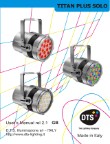
FOS 100 FULL RGBW
FOS 100 FULL WHITE CT
User’s Manual rel 4.1 FC-CT
D.T.S. Illuminazione s.r.l. - ITALY
http://www.dts-lighting.it
FOS 100 SOLO FULL RGBW FOS 100 FULL RGBW
FOS 100 SOLO FULL WHITE CT FOS 100 FULL WHITE CT

FOS 100
Le informazioni contenute in questo documento sono state attentamente redatte e controllate. Tuttavia
non è assunta alcuna responsabilità per eventuali inesattezze. Tutti i diritti sono riservati e questo
documento non può essere copiato, fotocopiato, riprodotto per intero o in parte senza previo consenso
scritto della D.T.S .
DTS si riserva il diritto di apportare senza preavviso cambiamenti e modifiche estetiche , funzionali o di
design a ciascun proprio prodotto. D.T.S non assume alcuna responsabilità sull’uso o sull’applicazione dei
prodotti o dei circuiti descritti.
The information contained in this publication has been carefully prepared and checked. However, no
responsibility will be taken for any errors. All rights are reserved and this document cannot be copied,
photocopied or reproduced, in part or completely, without prior written consent from D.T.S.
D.T.S. reserves the right to make any aesthetic, functional or design modifications to any of its products
without prior notice. D.T.S. assumes no responsibility for the use or application of the products or circuits
described herein.
Les informations contenues dans le présent manuel ont été rédigées et contrôlées avec le plus grand
soin. Nous déclinons toutefois toute responsabilité en cas d'éventuelles inexactitudes. Tous droits
réservés. Ce document ne peut être copié, photocopié ou reproduit, dans sa totalité ou partiellement,
sans le consentement préalable de .
se réserve le droit d'apporter toutes modifications et améliorations esthétiques, fonctionnelles ou
de design, sans préavis, à chacun de ses produits. décline toute responsabilité sur l'utilisation ou
sur l'application des produits ou des circuits décrits.
D.T.S
D.T.S.
D.T.S.
Las informaciones contenidas en este documento han sido cuidadosamenteredactadas y
controladas. Con todo, no se asume ninguna responsabilidad por eventuales inexactitudes.
Todos los derechos han sido reservados y este documento no puede ser copiado, fotocopiado
o reproducido, total o parcialmente, sin previa autorizaciónescrita de
se reserva el derecho a aportar sin previo aviso cambios y modificaciones de carácter
estético, funcional o de diseño a cada producto suyo. no se asume responsabilidad de
ningún tipo sobre la utilización o sobre la aplicació
n de los productos o de los circuitos descritos.
D.T.S.
D.T.S.
D.T.S.
2

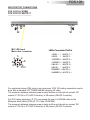
DESCRIPTION
M12 connection system between Power supply and LED bar (All versions)
Powercon + XLR connectors (FOS 100 SOLO IP20)
Harting connectors (FOS 100 SOLO IP65 )
FOS 100 is a new compact self-contained LED bar designed for colouring large surfaces with a uniform
projection, either indoor and outdoor.
FOS 100 can be used for many applications, such as: professional, for an ample range of special events;
theatre and television, for uniform background colours and cycloramas; architectural, for lighting building
facades, public and commercial spaces, monuments, etc.
FOS 100 is made on aluminium and steel offering high resistance to mechanical stress, with an IP65
protection rating.
FOS 100 length is 99 cm.
Various FOS 100 units can be easily connected together: the LEDs distribution pattern guarantees no
black spaces between the LEDs of in-line bars, and an even coverage of lighted surfaces.
FOS 100 is available with or without a Z10 integrated power supply.
The Z10 power supply is available either with IP65 or IP20 protection rating.
Three dedicated lenses sets (Spot, Medium flood, Wide flood) are available for each model, offering
different light beam projection angles.
FOS 100 SOLO can be controlled via any DMX lighting console.
FOS 100 range comprises various models, which employ different sets of LEDs tailored for distinct
applications:
FOS 100 FULL RGBW
FOS 100 FULL WHITE CT
FOS 100 FULL RGBW and FOS 100 SOLO FULL RGBW
15 x Ostar FULL RGBW LEDs • Integrated power supply (FOS 100 SOLO FULL RGBW)
FOS 100 FULL WHITE CT and FOS 100 SOLO FULL WHITE CT
15 x Ostar FULL WHITE LEDs • Integrated power supply (FOS 100 SOLO FULL WHITE CT)
All FOS 100 SOLO models are available with Z10 power supply IP65 or IP20 rated
All FOS 100 models are also available without integrated power supply
All FOS 100 models are also available with spot / medium flood / wide flood lenses
LED technology
FOS 100 / FOS 100 SOLO FULL RGBW: 15 x Ostar FULL RGBW LEDs
16 million colours; colour temperature range 2700°K ÷ 8000°K
FOS 100 / FOS 100 SOLO FULL WHITE CT: 15 x Ostar FULL WHITE LEDs
16 million colours; colour temperature range 2700°K ÷ 6500°K
No infrared emission; no ultraviolet emission
LEDs average lifespan: 100.000 hours
Optical units
3 lenses sets available (Spot, Medium flood, Wide flood)
Control
Via any DMX lighting console
Protection
FOS 100: IP65 protection level
FOS 100 SOLO: IP65 or IP20 protection level
Construction
FOS is made on aluminium and steel
Power supply
Integrated (FOS 100 SOLO) power supply / LED controller (Z10 IP65 or Z10 IP20);
External (FOS 100) dedicated Z1 PLUS (IP20 or IP65) or Z8 power supplies / LED controllers
Power consumption
Max 110W
Connection
3
FOS 100

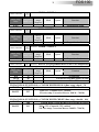
MAIN ELECTRICAL CHARACTERISTICS (FOS 100 SOLO FULL RGBW / FULL WHITE CT)
Input Voltage Range : Vin 90 - 260 VAC
Frequency : 50 - 60 Hz
Power Factor (Pf) : 0.95 electronic PFC controller
Efficiency : 90% typical
Output:
Output Current : 350 mA @ 100% per channel (500mA @ 100% per channel in BOOST Mode)
Output Voltage : Vout 70V
Control Input:
Control Signal : DMX 512
Dimming System : Constant Current PWM
Address Range : DMX 512 channels addressable by display
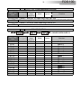
ACCESSORIES
• Lenses set Spot available for each model
• Lenses set Medium flood available for each model
• Lenses set Wide flood available for each model
• 4x2xAWG24 Multipolar black cable (Code 0509C062)
• M12 female (8 poles) cable connector (Code 0520P050)
• M12 male (8 poles) cable connector (Code 0520P051)
• Z1 PLUS IP20 Power supply / LED controller (Code 03.LA.009P)
• Z1 PLUS IP65 Power supply / LED controller (Code 03.LA.009P.IP65)
• Z8 IP20 Power supply / LED controller (Code 03.LA.075.V2)
IMPORTANT SAFETY INFORMATION
Fire prevention:
Never locate the fixture on any flammable surface.
Minimum distance from flammable materials: 10 cm.
Replace any blown or damaged fuses only with those of identical value.
Prevention from electric shock:
High voltage is present inside the unit.
Unplug the unit prior to performing any operation which involves touching the inside of the unit.
This equipment must be grounded, do not connect to non-grounded supplies.
Use only AC supplies 90-260 V, 50-60 Hz.
FOS 100 SOLO IP20 model should never be located in position exposed to rain or in areas of
extreme humidity.
A good air ventilation is essential for proper equipment work.
Safety:
The external surface of the unit may exeed 50°C; never handle the unit until at least 5 minutes
have elapsed since the unit was turned off.
The use of a thermal magnetic circuit breaker is recommended for each FOS 100 SOLO unit.
4
FOS 100

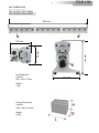
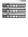
UNIT DIMENSIONS:
FOS 100 SOLO FULL RGBW
FOS 100 SOLO FULL WHITE CT
990 mm
100 mm
Unit Dimensions
(LxWxH)
990 x 100 x 78 mm
Weight
7 Kg
78
mm
1
6
0
mm
140 mm
Packing Dimensions
(LxWxH)
1060 x 160 x 200 mm
Weight
8,5 Kg
5
FOS 100

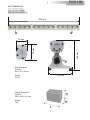
Packing Dimensions
(LxWxH)
1060 x 160 x 200 mm
Weight
7 Kg
990 mm
56 mm
78
mm
1
6
0
mm
140 mm
Unit Dimensions
(LxWxH)
990 x 56 x 78 mm
Weight
5,5 Kg
UNIT DIMENSIONS:
FOS 100 FULL RGBW
FOS 100 FULL WHITE CT
6
FOS 100

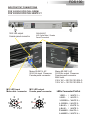
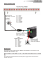
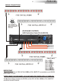
INPUT/OUTPUT CONNECTIONS
FOS 100 SOLO IP20 FULL RGBW
FOS 100 SOLO IP20 FULL WHITE CT
Mains 90-260 V AC
50-60 Hz input Powercon
Female panel connector
DMX IN/OUT
XLR 5 pins Male / Female
Panel Connectors
7
Pin1
2
3
4
5
6
7
M12 LED output
Female panel connector
Mains 90-260 V AC
50-60 Hz output Powercon
Female panel connector
MAX load:
230 V AC = 20 FOS 100 SOLO
100 V AC = 10 FOS 100 SOLO
Pin1
2
3
4
5
6
7
M12 LED input
Male cable connector
FOS 100
LEDs Connector PinOut
4-GREEN - / WHITE 2 -
5-BLUE + / WHITE 3 +
6-BLUE - / WHITE 3 -
7-AMBER - / WHITE 4 -
8-AMBER + / WHITE 4 +
1-RED + / WHITE 1 +
2-RED - / WHITE 1 -
3-GREEN + / WHITE 2 +
7-
8
8
M12 LED output
Female panel connector

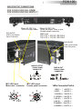
INPUT/OUTPUT CONNECTIONS
FOS 100 SOLO IP65 FULL RGBW
FOS 100 SOLO IP65 FULL WHITE CT
Mains 90-260 V Ac
50-60 Hz output ILME 5 pins
Female panel connector
MAX load:
230 V AC = 20 FOS 100 SOLO
100 V AC = 10 FOS 100 SOLO
DMX IN/OUT
ILME 4 pins Female
Panel Connectors
8
M12 LED output
Female panel connector
Mains 90-260 V Ac
50-60 Hz input cable
M12 LED input
Male cable connector
FEMALE PANEL
CONNECTOR
MAINS OUTPUT
1
3
2
4
FEMALE PANEL
CONNECTOR
DMX IN-OUT
LEDs Connector PinOut
FOS 100
Pin1
2
3
4
5
6
7
Pin1
2
3
4
5
6
7
8
8
DMX IN/OUT
ILME 4 pins Female
Panel Connectors
4-GREEN - / WHITE 2 -
5-BLUE + / WHITE 3 +
6-BLUE - / WHITE 3 -
7-AMBER - / WHITE 4 -
8-AMBER + / WHITE 4 +
1-RED + / WHITE 1 +
2-RED - / WHITE 1 -
3-GREEN + / WHITE 2 +
7-

INPUT/OUTPUT CONNECTIONS
FOS 100 FULL RGBW
FOS 100 FULL WHITE CT
FOS 100
M12 LED input
Male cable connector
LEDs Connector PinOut
For application where IP65 rating is not necessary, FOS 100 cabling connection can be
done with a standard UTP B2 category 5E cable.
The maximum distance between power supply and the unit should not exceed 100
meters (Z1 PLUS or Z10 LED Controller) or 50 meters (Z8 LED Controller).
For IP65 rating application, D.T.S. reccomend the use of a IP65/68 cable as the
Multipolar black cable (IP68) (D.T.S. Code: 0509C062).
The maximum distance between power supply and the unit should not exceed 100
meters (Z1 PLUS or Z10 LED Controller) or 50 meters (Z8 LED Controller).
TIA/EIA 568-
Pin1
2
3
4
5
6
7
8
9
4-GREEN - / WHITE 2 -
5-BLUE + / WHITE 3 +
6-BLUE - / WHITE 3 -
7-AMBER - / WHITE 4 -
8-AMBER + / WHITE 4 +
1-RED + / WHITE 1 +
2-RED - / WHITE 1 -
3-GREEN + / WHITE 2 +
7-

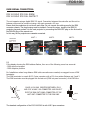
DMX SIGNAL CONNECTION:
FOS 100 SOLO IP20 FULL RGBW
FOS 100 SOLO IP20 FULL WHITE CT
The unit operates using a digital DMX 512 signal. Connection between the controller and the unit or
between units must be carried out using a two pair screened ø 0.5 mm.
P. S :
If the display showing the DMX address flashes, then one of the following errors has occurred:
- DMX signal not present
- DMX reception problem
For Installations where long distance DMX cable connections are needed, we suggest to use a DMX
terminator.
The DMX terminator is a male XLR 3-5 pins connector with a 120 ohm resistor Between pin 2 and 3.
The DMX terminator must be plugged into the last unit (DMX out panel connector) of the DMX line.
Ensure that the conductors do not touch each other. Do not connect the cable ground to the DMX
connector chassis. The plug housing must be isolated. Connect the mixer signal to the DMX IN
projector plug and connect it to the next projector by connecting the DMX OUT plug on the first unit to
the DMX IN plug of the second one.
In this way, all the projectors are cascade connected.
The standard configuration of the FOS 100 SOLO is with XLR 5 pins connectors.
5
3
4 2
1
1=GND
2=DATA-
3=DATA+
CONTROLLER
STANDARD
DMX 512
1
2
3
5
4
OUT
120 ohm
PIN 3
PIN 2
PLACE A 120 OHM RESISTOR BETWEEN PIN 2
AND 3 OF A MALE XRL CONNECTOR AND PLUG IT
INTO THE DMX OUT PANEL CONNECTOR OF THE
LAST UNIT CONNECTED TO THE DMX LINE
FOS 100
10
UNIT 1 UNIT 2 UNIT 3

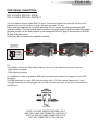
DMX SIGNAL CONNECTION:
FOS 100 SOLO IP65 FULL RGBW
FOS 100 SOLO IP65 FULL WHITE CT
The unit operates using a digital DMX 512 signal. Connection between the controller and the unit or
between units must be carried out using a two pair screened ø 0.5 mm.
P. S :
If the display showing the DMX address flashes, then one of the following errors has occurred:
- DMX signal not present
- DMX reception problem
For Installations where long distance DMX cable connections are needed, we suggest to use a DMX
terminator.
The DMX terminator is a male DMX cable connector with a 120 ohm resistor Between pin 2 and 3.
The DMX terminator must be plugged into the DMX out panel connector of the last unit connected to
the DMX line.
Ensure that the conductors do not touch each other. Do not connect the cable ground to the DMX
connector chassis. The plug housing must be isolated. Connect the mixer signal to the DMX IN projector
plug and connect it to the next projector by connecting the DMX OUT plug on the first unit to the DMX
IN plug of the second one.
In this way, all the projectors are cascade connected.
PLACE A 120 OHM RESISTOR BETWEEN PIN 2
AND 3 OF A MALE DMX CONNECTOR AND PLUG IT
INTO THE DMX OUT PANEL CONNECTOR OF THE
LAST UNIT CONNECTED TO THE DMX LINE
5
3
4 2
1
1=GND
2=DATA-
3=DATA+
CONTROLLER
STANDARD
DMX 512
MALE CABLE
CONNECTOR
DMX
120 OHM
11
FOS 100

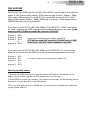
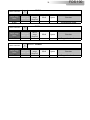
DMX ADDRESS
Projector 1 A001
Projector 2 A011 If you want to select the next projector, just add “10”
Projector 3 A021
….. A….
projector 6 A051
Selecting the DMX address
1) Press the UP-DOWN key until you reach the required DMX address. The numbers on the
display will start to flash (but the new DMX address hasn't yet been set).
2) Press ENTER to confirm your selection. The numbers on the display will stop flashing and the
projector is now controlled by the new DMX address.
TIPS: if you keep pushed the UP or DOWN keys, the channels are calculated more quickly and
you get a faster selection.
FOS 100 SOLO FULL RGBW and FOS 100 SOLO FULL WHITE CT can be used in seven different
modes: 10 DMX channels mode (default), 6 DMX channels mode (Shutter + Dimmer + RGBA),
WALL mode (6 DMX channels; for use with DTS Wall mounted DMX controller 0514L007), M4CH
mode (5 DMX channels; Dimmer + RGBA), RGBA mode (4 channels), 1 DMX channel mode or
CUSTOM DMX mode (not yet implemented).
If you want to use the FOS 100 SOLO FULL RGBW or FULL WHITE CT in “WALL” mode, select
the “WALL” mode from the MODE menu and set the following addresses on the mixer: (To be
used only with DTS Wall mounted DMX controller 0514L007)
Projector 1 A001
Projector 2 A006
Projector 3 A012
….. A….
projector 6 A030
If you want to use the FOS 100 SOLO FULL RGBW or FULL WHITE CT in 10 channels mode,
select the 10 CH mode from the MODE menu and set the following addresses on the mixer:
FOS 100
12
If you want to select the next projector, just add “6”
DTS Wall mounted DMX controller 0514L007 assign 6 DMX
channels per unit also if some channels are not used

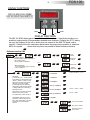
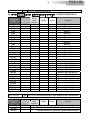
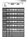
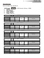
DISPLAY FUNCTIONS
DISPLAY FUNCTIONS
The FOS 100 SOLO display panel shows all the available functions . Using these functions, it is
possible to change some of the parameters and add some functions. Changing the D.T.S. setting
can vary the functions of the unit so that it does not respond to the DMX 512 signal used to
control it. Carefully follow the instructions below before carrying out any variations or selections.
NOTE: the symbol shows which key has to be pushed to obtain the desired function.
Software version 5.03
FOS 100 SOLO FULL RGBW
FOS 100 SOLO FULL WHITE CT
FOS 100
13
DOWN
UP
ENTER
MENU
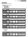
Up-DownMENU ENTER
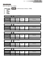
DMX MODE
To select DMX mode : 10 DMX channels
mode (default), 6 DMX channels mode
(Shutter + Dimmer + RGBA), 15 DMX
channels mode, WALL mode (6 DMX
channels; for use with DTS Wall
mounted DMX controller 0514L007),
M4CH mode (5 DMX channels; Dimmer
+ RGBA), RGBA mode (4 channels), 1
DMX channel mode.
M4CH (5 CHANNELS)
Up-Down
Up-Down
ENTER
ENTER
Up-Down
MENU
ENTERUp-Down
REVERSE DISPLAY
Reverses display's reading depending on
the mounting position
(On the ground or suspended).
Up-Down
Floor
position
Suspension
position
Up-DownENTER
Up-DownENTER
DISPLAY STAND BY
To turn off the display (after 5 seconds)
or leave it always on.
Display OFF
Display
always ON
ENTER
ENTER
ENTER
ENTER
Default DMX Mode = 10 CH
10 CHANNELS
Up-Down
Up-DownENTER
ENTER
ENTER
ENTER
Custom mode enabled
Show Custom settings
Parameters Setting on
Custom Mode
CUSTOM DMX mode let you set the
parameters for Shutter, Dimmer, Red,
Green, Blue, Amber, White, CTC, Macro
and Function to the desired DMX
channels.
AUX mode let you activate an external
ON-OFF control on IR connector.
(not implemented on FOS 100 SOLO)
15 CHANNELS
Up-Down
ENTER
WALL (6 CHANNELS)
Up-Down
ENTER
Up-Down
ENTER
6 CHANNELS
RGBA (4 CHANNELS)
Up-Down
ENTER
Shutter + Dimmer + RGBA
Dimmer + RGBA
1 CHANNEL

FOS 100
14
Up-Down
MENU
ENTERUp-Down
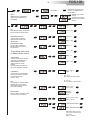
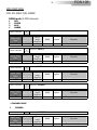
LED
RGBA Min/Max, Smooth, Compression,
Sync and Boost level values settings
Up-Down
Up-DownENTER
Up-DownENTER
ENTER
ENTER
ENTER
ENTER
Up-Down
Up-DownENTER
ENTER
ENTER
RGBA MINIMUM VALUES
This menu allow to select the
minimum levels for Red, Green,
Blue and Amber
RGBA MAXIMUM VALUES
This menu allow to select the
maximum levels for Red, Green,
Blue and Amber
Default = 255
Default = 0
Default = 0
Default = 0
Default = 255
Default = 255
These settings have priority
on Master Dimmer channel
Up-Down
Up-DownENTER
ENTER
Range = Off-20
Default = 4
SMOOTH VALUE
This menu allow to select the value
of the delay (in milliseconds) for
RGBA and Dimmer channels
reaction to DMX or Program
variation.
Off=25 ms delay (Fast response)
20=250 ms delay (Slow response)
Off = 25 ms
Istant responce to DMX variation
20 = 250 ms
Smooth response to DMX variation
Up-Down
Up-DownENTER
ENTER
Linear = Linear
current output
COMPRESSION
This menu allow to select between
Linear current output or Quadratic
current output for LEDs
Default = Linear
Quadratic =
Linear light
output
ENTER
SYNC
This menu allow to adjust the PWM
frequency value (Hz) in order to
reduce flickering in the process of
your camera recordings
Up-Down
Up-DownENTER
Range = 610 Hz -10 KHz
Default = 610 Hz
ENTER
Boost mode activated
With BOOST active, the LED’s
current is set to 500 mA (30%
more gain).
Default = Disabled
Up-DownENTER
ENTER
BOOST DRIVING
This menu allow to increase the LED’s
current from 350 mA to 500 mA
Boost mode deactivated
Up-Down
ENTER
AUX MODE
External ON - OFF control on IR
connector (not implemented on
FOS 100 SOLO)
Up-Down
ENTER
MENU ENTER
Up-Down
Standard mode enabled:
(Default).
Extended mode enabled:
Rainbow effects on MACRO
channel.
ENTER
Up-Down
Up-DownENTER
ENTER
MACRO
MACRO Function, enable channel
mapping macro rainbow effects
STD (default)
Up-Down
Up-DownENTER
ENTER
ENTER
Default = 0
Default = 255

15
FOS 100
Up-DownENTER ENTER
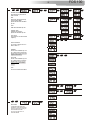
WHITE MACROS
16 macros for White color from
2800 to 6500 ° K
Up-DownENTER
Up-DownENTER
ENTER
ENTER
DIMMER
Dimmer level selectable by user
as on DMX channel 2 (Dimmer)
Dimmer level is active for all the
programs and macros
SHUTTER
Shutter level selectable by user
as on DMX channel 1 (Shutter)
Shutter level is active only for
CU01/CU16 and Wh01/Wh16
macros
ESC
Esc from Automatic Mode Menu
ENTER
MENU
Up-Down
Up-DownENTER ENTER
Up-Down
ENTER
AUTOMATIC MODE
Automatic demo game without
DMX controller
ChPr
Chase with 16 steps previously
created in REC MODE
Speed and Wait time selectable
by user
ENTER
ENTER
Up-Down
CUPr
RGB values selectable by user
Rainbow (rAIn)
Rainbow colours effect.
Speed time selectable by user
ENTER
ENTER
Up-Down
CU01-CU16
Color Macros as on DMX channel
8 (Macro)
Up-DownENTER ENTER
MENU
Up-Down
ENTER
ENTER
REC MODE
In DMX Recorder Mode,it is
possible to create and store the
scenes of the ChPr by using an
external DMX controller.
The unit must be set to 10
channels MODE

FOS 100
16
Up-DownENTER
ENTER
MENU
Up-Down
ENTER
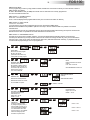
SLAVE MODE
Slave mode for ChPr program.
All slave units will be
synchronised with master unit,
running their own Chpr program.
Up-DownENTER
MENU
Up-Down
ENTER
INFRARED MODE
Infrared remote control.
By activating Ir MODE, it will be
possible to navigate trought the
unit functions by using the D.T.S.
infrared remote control.
D.T.S. Code :0514L008
NOTE:
External infrared remote sensor
needed.
D.T.S. Code :03.LA.016
NOT IMPLEMENTED ON FOS 100
EMERGENCY
Emergency operating mode.
By setting Emergency mode, it
will be possible to select one of
the 16 preprogrammed WHITE
cues that will then ran if DMX
signal is missing or not available.
Usefull for Emergency EXIT
ilumination on public areas.
Up-Down
MENU
Up-DownENTER
Up-DownENTER
ENTER
ENTER
Default = OFF
Default = White 1
Default = 255
ENTER
DMX Recorder Mode
For the programming of ChPr by using a DMX controller, besides the 10 channels necessary to control the unit a further 3
DMX channels are needed.
So that in RECORDER mode (via DMX) the unit will need 13 channels to be correctly programmed.
The three new DMX channels are:
DMX channel 11 = SCENES channel
From 0-10 = no function (r001)
From 11-255 are displayed the programmable scenes (max 16 scenes from M001 to M0016 )
DMX channel 12 = EDIT channel:
-From 0-19 = no function
-From 20-234 the unit runs the configuration given by the received input DMX values.
With the channel SCENES it is possible to pass from one step to the next while with REC it is possible to record the
selected scene.
-From 235-255 the unit runs the configuration given by the received input DMX values closing the sequence as last scene.
With the channel REC it is possible to record the selected scene as last scene.
DMX channel 13 = RECORDING channel
Records the set scene with a variation between 0 to 255 (the display flashes indicating that the scene has been
recorded).It is advised that you keep the REC channel set to 0 and to run through the 255 only once you have decided to
save the scene. If ChPr is not closed, by indicating the last scene ( Edit channel between 235-255), in playback mode all
16 scenes will be played through even if not programmed
Up-DownENTER
MENU
Up-Down
ENTER
FAN SPEED CONTROL
Internal Fan Speed control
selectable by user.
Range: OFF - 24 volt
Default : 12 volt
Fan Speed Control
Range: OFF - 24 volt
Default = 12 volt
Up-DownENTER
MENU
Up-Down
ENTER
WIRELESS DMX
Wireless DMX enabled/disabled.
Wireless DMX receiver kit on FOS
100 is available on request.
WIRELESS DMX Disabled
(Default)
WIRELESS DMX Enabled
Up-Down
ENTER
UNLINK = LOG OUT

ENTER
Up-DownENTER
LIFE TIME
This menu show the total UNIT life time
and the RGBA life time
Up-Down
MENU
ENTER
Up-Down
MENU
SOFTWARE
Software version
ENTER
TEST MODE
RGBA colours test with rainbow
Up-Down
MENU
FOS 100
17
.
ENTERENTER
Up-Down
MENU
DEFAULT
To restore default settings
Internal Unit temperature.
(° Celsius)
ENTERENTER
Up-Down
MENU
TEMPERATURE
Internal Unit temperature
visualisation
.
.

FOS 100
18
SERVICE MENU
For technical personnel only
To operate this menu:
-Connect the unit to the main
-While reset is running, press the MENU and ENTER keys at the same time.
EXIT
Exit from Service menu.
CHANNELS
This menu allow to set 3 channels or 4 channels LEDs output mode
3 CH = RGB mode
4 CH = RGBA mode (Default)
PRODUCT MODEL SELECTION:
TITAN = for TITAN PLUS and FOS 100 units (Default)
STRIP = only for FOS 100 POWER units
DELTA 8 = only for DELTA 8 units
POWER LIMITATION PARAMETER
Range: 0% - 100%
100% (Default)

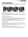
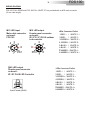
AUTOMATIC OPERATION (AUTO):
FOS 100 SOLO can work in automatic mode without a DMX controller. First of all connect the projectors
with a DMX cable (picture below). A maximum quantity of 32 slave units can be connected to the same
Master unit.
To activate Auto mode on the first unit, use the menu to run through the different modes until AUTO
appears on the display, and press enter.
Now it is possible to choose between the different pre-programmed games (CUPr-RAIn-CU01/CU16-
Wh01/Wh16) or ChPr which is user programmable through REC mode. To confirm game activation press
ENTER on the selected GAME.
CUPr-RAIn-CU01/CU16-Wh01/Wh16
The first unit that will work as a Master should be placed in Automatic mode (AUTO), the other units
have to be placed in 10 DMX channels mode (MODE 10CH) and the DMX address should be set at A001.
For RaIn (rainbow) game it is possible to select the speed for the colour changhing (SPEE).
DIMMER function (in AUTOMATIC MODE) is active for all the programs.
SHUTTER function (in AUTOMATIC MODE) is active only for CU01/CU16 and Wh01/Wh16 macros.
ChPr MASTER/SLAVE
The first unit that will function as a Master must be set to Automatic mode (AUTO), the other units must
be set to Slave mode (SLAV), selectable through the menu. In this way all the Slave units will be
synchronised with the master and running their own ChPr game.
On the master unit it is possible to vary the Speed time (SPEE) for the colour changhing and the Wait
time (UAIt) between the steps.
Speed time and Wait time on the Master, have priority on the slave units.
NB: It is possible to run GA.Pr on the other units even though these do not have GA.Pr programmed.
You can do this by setting the units to 10 DMX channels mode and selecting DMX address A001.
MASTER SLAVE 1
SLAVE 2
SLAVE 32
FOS 100
19

Rec mode
It is possible to program your own game on the FOS 100 SOLO FULL RGBW / FOS 100 SOLO FULL
WHITE CT that will then run it in AUTO mode (ChPr).
Each unit can have its own programmed game.
In REC mode the unit must be set to 10 DMX channels mode.
To program the ChPr by using a DMX controller, you need 3 more channels in addition to the 10 channels
necessary to control the unit.
So that in RECORDER mode (via DMX) the unit will need 12/13 DMX channels to be correctly
programmed.
The three new DMX channels are:
DMX channel 11 = SCENES channel
From 0-10 = no function (r001)
From 11-255 are displayed the programmable scenes (max 16 scenes from M001 to M0016)
DMX channel 12 = EDIT channel:
-From 0-19 = no function
-From 20-234 the unit runs the configuration given by the received input DMX values.
With the channel SCENES it is possible to pass from one step to the next while with REC it is possible to
record the selected scene.
-From 235-255 the unit runs the configuration given by the received input DMX values closing the
sequence as last scene.
With the channel REC it is possible to record the selected scene as last scene.
DMX channel 13 = RECORDING channel
Records the set scene with a variation between 0 to 255 (the display flashes indicating that the scene
has been recorded).It is advised that you keep the REC channel set to 0 and to run through the 255 only
once you have decided to save the scene. If ChPr is not closed, by indicating the last scene (Edit channel
between 235-255), in playback mode all 16 scenes will be played through even if not programmed.
FOS 100
20
La pagina si sta caricando...
La pagina si sta caricando...
La pagina si sta caricando...
La pagina si sta caricando...
La pagina si sta caricando...
La pagina si sta caricando...
La pagina si sta caricando...
La pagina si sta caricando...
La pagina si sta caricando...
La pagina si sta caricando...
La pagina si sta caricando...
La pagina si sta caricando...
La pagina si sta caricando...
La pagina si sta caricando...
La pagina si sta caricando...
La pagina si sta caricando...
La pagina si sta caricando...
La pagina si sta caricando...
La pagina si sta caricando...
La pagina si sta caricando...
La pagina si sta caricando...
La pagina si sta caricando...
La pagina si sta caricando...
La pagina si sta caricando...
-
 1
1
-
 2
2
-
 3
3
-
 4
4
-
 5
5
-
 6
6
-
 7
7
-
 8
8
-
 9
9
-
 10
10
-
 11
11
-
 12
12
-
 13
13
-
 14
14
-
 15
15
-
 16
16
-
 17
17
-
 18
18
-
 19
19
-
 20
20
-
 21
21
-
 22
22
-
 23
23
-
 24
24
-
 25
25
-
 26
26
-
 27
27
-
 28
28
-
 29
29
-
 30
30
-
 31
31
-
 32
32
-
 33
33
-
 34
34
-
 35
35
-
 36
36
-
 37
37
-
 38
38
-
 39
39
-
 40
40
-
 41
41
-
 42
42
-
 43
43
-
 44
44


DTS FOS 100 FULL RGBW Manuale utente
- Categoria
- Proiettori
- Tipo
- Manuale utente
- Questo manuale è adatto anche per
in altre lingue
- English: DTS FOS 100 FULL RGBW User manual
Documenti correlati
-
 DTS FOS 100 FULL RGBW Manuale utente
-
 DTS TITAN PLUS SOLO Manuale utente
-
 DTS F-25 Manuale utente
-
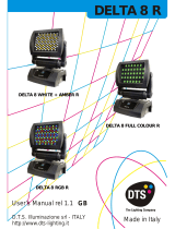 DTS Delta 8 Full Colour R Manuale utente
-
 DTS DRIVENET 1664 Manuale utente
-
 DTS Brick Manuale utente
-
 DTS DELTA 12 HEAD Manuale utente
-
 DTS SCENA LED 80 FR FC Manuale utente
-
 DTS SCENA LED 120 HQS Manuale utente
-
 DTS Nick Wash 600 Manuale utente