MULTIPLEX Blizzard Building Instructions
- Categoria
- Giocattoli telecomandati
- Tipo
- Building Instructions
Questo manuale è adatto anche per

1
BK / KIT Blizzard # 21 4233
vorgesehen für den MULTIPLEX
Brushless-Antrieb # 33 2639
oder Tuning # 33 2643
F
GB
D
E
I
Bauanleitung 3 ... 8
Notice de construction 9 ... 14
Building instructions 15 ... 26
Instruzioni di montaggio 27 ... 32
Instrucciones de montaje 33 ... 38
Ersatzteile
Replacement parts
Pièces de rechanges
Parti di ricambio
Repuestos
39 ... 40
© Copyright by MULTIPLEX 2008 Version 1.2

3
D
F
GB
I
E
Sicherheitshinweise
-
Prüfen Sie vor jedem Start den festen Sitz des Motors und der Luftschraube - insbesondere nach dem Transport, härteren Landungen
sowie Abstürzen. Prüfen Sie ebenfalls vor jedem Start den festen Sitz und die richtige Position der Tragflächen auf dem Rumpf.
- Akku erst einstecken, wenn Ihr Sender eingeschaltet ist und Sie sicher sind, daß das Bedienelement für die Motorsteuerung auf "AUS"
steht.
- Im startbereiten Zustand nicht in den Bereich der Luftschraube greifen.
Vorsicht in der Luftschraubendrehebene - auch Zuschauer zur Seite bitten!
- Zwischen den Flügen die Motortemperatur durch vorsichtige Fingerprobe prüfen und
vor einem Neustart den Motor ausreichend abkühlen lassen. Die Temperatur ist richtig, wenn Sie den Motor problemlos berühren
können. Insbesondere bei hohen Außentemperaturen kann dieses bis zu 15 Minuten dauern.
- Denken Sie immer daran: Niemals auf Personen und Tiere zufliegen.
Conseils de sécurité
-
Avant chaque décollage, vérifiez la fixation du moteur et de l'hélice, notamment après le transport, après les atterrissages violents et
après un “Crash”. Vérifiez également, avant chaque décollage la fixation ainsi que le positionnement de l’aile par rapport au fuselage.
- Ne branchez l’accu de propulsion que si vous êtes sûr que votre émetteur est allumé et que l’élément de commande moteur est en
position “ARRET”.
- Ne mettez pas vos doigts dans l’hélice! Attention à la mise en marche, demandez également aux spectateurs de reculer.
- Entre deux vols, vérifiez en posant un doigt dessus, la température du moteur, laissezle refroidir suffisamment avant le prochain
décollage. La température est correcte si vous pouvez maintenir votre doigt ou votre main sur le moteur. Le temps de refroidissement
peut varier jusqu’à 15 minutes s’il fait particulièrement chaud.
- Pensez-y toujours: ne volez jamais vers ou au-dessus des personnes ou des animaux.
Safety notes
- Before every flight check that the motor and propeller are in place and secure - especially after transporting the model, and after hard
landings and crashes. Check also that the wing is correctly located and firmly secured on the fuselage before each flight.
- Don’t plug in the battery until you have switched on the transmitter, and you are sure that the motor control on the transmitter is set to
“OFF”.
- When the model is switched on, ready to fly, take care not to touch the propeller. Keep well clear of the propeller disc too, and ask
spectators to stay back.
- Allow the motor to cool down after each flight. You can check this by carefully touching the motor case with your finger. The
temperature is correct when you can hold your finger on the case without any problem. On hot days this may take up to 15 minutes.
- Please keep in mind at all times: don’t fly towards people or animals.
Note di sicurezza
- Prima di ogni decollo controllare che il motore e la eliche siano fissati stabilmente - specialmente dopo il trasporto, atterraggi duri e se il
modello è precipitato. Controllare prima del decollo anche il fissaggio e la posizione corretta delle ali sulla fusoliera.
- Collegare la batteria solo quando la radio è inserita ed il comando del motore è sicuramente in posizione ”SPENTO”.
- Prima del decollo non avvicinarsi al campo di rotazione della eliche. Attenzione alla eliche in movimento - pregare che eventuali spettatori
si portino alla dovuta distanza di sicurezza!
- Tra un volo e l’altro controllare cautamente con le dita la temperatura del motore e farli raffreddare sufficientemente prima di ogni nuovo
decollo. La temperatura è giusta se si possono toccare senza problemi. Specialmente con una temperatura esterna alta questo può
durare fino a 15 minuti.
- Fare attenzione: Non volare mai nella direzione di persone ed animali.
Advertencias de seguridad
- Compruebe antes de cada despegue que el motor y la hélice estén fuertemente sujetados, sobretodo después de haberlo transportado,
de aterrizajes más fuertes así como después de una caída. Compruebe igualmente antes de cada despegue que las alas estén bien
sujetas y bien colocadas en el fuselaje.
- Conectar la batería, cuando la emisora esté encendida y Usted esté seguro que el elemento de mando para el motor esté en ”OFF”.
- No meter la mano en la zona inmediata a la hélice cuando el avión esté a punto de despegar. ¡Cuidado con la zona de la hélice! ¡Pedir a
los espectadores que se aparten!
- Entre los vuelos hay que comprobar cuidadosamente la temperatura del motor con el dedo y dejar que el motor se enfríe antes de volver
a despegar. La temperatura es correcta, si puede tocar el motor sin problemas. Sobretodo en el caso de temperaturas del ambiente muy
altas, esto puede tardar unos 15 minutos.
- Recuerde: No volar nunca hacía personas o animales.

15
# 21 4233
Examine your kit carefully!
MULTIPLEX model kits are subject to constant quality checks throughout the production process, and we sincerely hope that you
are completely satisfied with the contents of your kit. However, we would ask you to check all the parts before you start
construction, referring to the Parts List, as we cannot exchange components which you have already modified. If you find any
part is not acceptable for any reason, we will readily correct or exchange it once we have examined the faulty component. Just
send the offending part to our Model Department. Please be sure to include the purchase receipt and the enclosed complaint
form, duly completed.
We are constantly working on improving our models, and for this reason we must reserve the right to change the kit contents in
terms of shape or dimensions of parts, technology, materials and fittings, without prior notification. Please understand that we
cannot entertain claims against us if the kit contents do not agree in every respect with the instructions and the illustrations.
Caution!
Radio-controlled models, and especially model aircraft, are by no means playthings in the usual sense of the term. Building
and operating them safely requires a certain level of technical competence and manual skill, together with discipline and a
responsible attitude at the flying field. Errors and carelessness in building and flying the model can result in serious
personal injury and damage to property. Since we, as manufacturers, have no control over the construction, maintenance
and operation of our products, we are obliged to take this opportunity to point out these hazards and to emphasise your
personal responsibility.
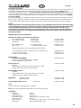
Additional items required for the “Blizzard”:
MULTIPLEX receiving system components for the Blizzard
RX-7-Synth IPD receiver 35 MHz A-band Order No. 5 5880
or RX-7-Synth IPD receiver 35 MHz B-band Order No. 5 5881
alternatively: 40 / 41 MHz band Order No. 5 5882
Nano-Karbonite servo 2 x required (ailerons) Order No. 6 5118
Nano-S servo 1 - 2 required (elevator (rudder)) Order No. 6 5120
Optional separation filter lead, 200 mm UNI (for speed controller)
4 x 200 mm UNI servo lead (2 x central connector, 2 x elevator servos) Order No. 8 5133
1 x High-current plug (green) Order No. 8 5213
1 x High-current socket (green) Order No. 8 5214
Battery charger:
MULTIcharger LN-3008 EQU Order No. 9 2540
for LiPo, LiIo and LiFe batteries (2S / 3S) and NiMH
and NiCd batteries (four to eight cells)
Blizzard power set: Order No. 33 2639
Contents:
Himax 3510-1100 motor, BL-37 II speed controller, 9 x 7” folding
propeller, taper collet, driver and 39 mm Ø spinner
Blizzard TUNING power set: Order No. 33 2643
Contents:
Himax 3516-1350 motor, BL-54 speed controller, 9 x 6” folding
propeller, taper collet, driver and 39 mm Ø spinner
Flight battery: Li-Batt BX 3/1-2100 Order No. 15 7131
or Li-Batt BX 3/1-2500 Order No. 15 7191
Receiver battery for glider version 4/2100-AA-W Order No. 15 6052
Tools:
Scissors, balsa knife, combination pliers, screwdriver.
Note: please remove the illustration pages from the centre of the instructions.
Specification:
Wingspan: 1380 mm
Overall length: 910 mm
All-up weight, glider: approx. 735 g
All-up weight, electric: approx. 820 / 925 g / Standard / Tuning
Total surface area: 19.4 dm²
Wing loading min.: 38 g/dm² glider, 42 g/dm² electric, 47 g/dm² electric (Tuning)
RC functions: Aileron, elevator, (rudder), motor
GB

16
Like any other aircraft, this model has static limits! Steep dives and silly, imprudent manoeuvres may cause structural
failure and the loss of the model. Please note: damage caused by incompetent flying is obvious to us, and we are not
prepared to replace components damaged in this way. It is always best to fly gently at first, and to work gradually towards
the model’s limits. The aircraft is designed to cope with our ‘Tuning’ (upgrade) power system, but is only capable of
withstanding the flight loads if it is built exactly as specified, and is in perfect structural order (i.e. not damaged). Further
upgrade measures are possible, but should only be attempted if you have plenty of experience in this field, as additional
structural reinforcements will be required.
Important note
This model is not made of styrofoam™, and it is not possible to glue the material using white glue, polyurethane or epoxy;
these adhesives only produce a superficial bond which gives way when stressed. Use medium-viscosity cyano-acrylate
glue exclusively, preferably our Zacki-ELAPOR®, # 59 2727 - the cyano glue optimised specifically for ELAPOR® particle
foam.
If you use Zacki-ELAPOR® you will find that you do not need cyano ‘kicker’ or activator for most joints. However, if you
wish to use a different adhesive, and are therefore obliged to use kicker / activator spray, we recommend that you apply
the material in the open air as it can be injurious to health.
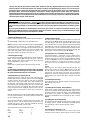
1. Before assembling the model
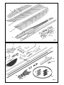
Please check the contents of your kit before you start working on
it.
You will find Figs. 1 + 2 and the Parts List helpful here.
Note: the GRP spar caps and fuselage longerons 11.1 - 11.9 are
supplied in the kit in the form of a continuous strip 11 (8.5 m
long), which has to be cut to length: take the dimensions of each
strip directly from the component, and cut them to length using
side-cutters immediately before gluing them in place. The
approximate lengths are stated in the Parts List.
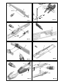
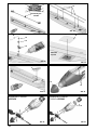
2. Preparing the fuselage
Lay the right-hand fuselage shell 4 down flat on the workbench
(table). Cut the longeron 11.5 to length and glue it in place as
shown, applying cyano along its whole length. Wipe off excess
adhesive immediately using a cloth.
Fig. 03
Repeat this procedure with the left-hand fuselage shell 3.
Caution:
It is absolutely essential that the fuselage shells are straight
when you install the GRP longerons. If you make a mistake at
this point, it will be impossible to correct it later!
3. Preparing the wing retainer plate 40
The first step here is to solder two servo leads, # 8 5133, to the
M6 MULTIPLEX high-current plug, # 8 5213, as shown in Fig. 04.
Carefully separate the servo ribbon cable into its individual
colours using a pair of side-cutters. Strip a little insulation from
the wire ends, and tin (apply solder to) the bare conductors. Tin
the individual contacts of the M6 plug. Slip a piece of heat-shrink
sleeve over each wire, and solder the wire ends to the contacts
in the arrangement shown in Fig. 4. Slip the sleeves over the
soldered joints and shrink them in place using a heat-gun or
similar.
Note that the M6 plug and socket should be fitted together before
you carry out the soldering - this ensures that the contacts take
up their optimum position.
Tin the contacts of the plug, solder the wires to the contacts, and
shrink the sleeves over the soldered joints. Position the plug
carefully and glue it in place. Push the nuts 32 into the wing
retainer plate 40 until they snap into place.
The standard wire colours of UNI servo leads:
red red +
black brown -
yellow orange
4. Fitting out the fuselage
Now we turn to the right-hand fuselage shell 4. First cut the inner
fuselage longeron 11.8 to length, and glue it in place using cyano.
The next step is to glue the canopy latches 22 in place, taking
care to position them accurately. Glue the prepared wing retainer
plate 40 in place with the projecting spigots flush at the top.
Deploy the leads as shown, and tape them to the fuselage sides.
Repeat this procedure with the left-hand fuselage shell 3 - with
the exception of the wing retainer plate 40. Fig. 05
5. Preparing the servo installation in the fuselage
The Blizzard features a V-tail which can be actuated using a
single servo (‘elevator’ function only; no rudder) or two servos. In
the former case there is no need to cut away additional material,
as shown in Fig. 06. If you wish to use both functions of the V-tail
(rudder and elevator), a second servo is required. In this case
you have to open up the additional servo well using a balsa
knife.
Fig. 06
The servo cases can now be sealed with adhesive tape, and
glued in their recesses as shown in Fig. 07. Before you do this,
use side-cutters to remove the superfluous arms from the servo
output levers, and snip off the servo leads close to the plugs.
Lengthen the cables by soldering 300 mm extension leads to
them; insulate each soldered joint with a separate heat-shrink
sleeve.
6. Completing the fuselage
Check that the fuselage shells fit together accurately, then glue
them together using cyano.
Fig. 08
7. Installing the nose fairing / motor bulkhead
Sand off the moulding pimples from the area of the fuselage
where the nose fairing / motor bulkhead 13 will fit. Apply cyano to
the mating surfaces, and glue the fairing / motor bulkhead 13 in
place, taking care to position it accurately. Press the fuselage
against the fairing 13 from the inside while the glue is setting.
Fig. 09
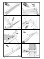
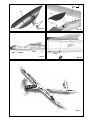
8. Installing the rear fuselage fairing
Here again sand off the pimples at the joint areas. Apply cyano to
the mating surfaces, position the fuselage fairing 14 carefully,
and hold it firmly in place until the adhesive hardens.
Fig. 10
9. Preparing the V-tail panels 7 + 8
Cut a slot about 1 mm wide at the end of each V-tail panel to
release the control surfaces, but take great care not to cut right

17
through the integral hinge! Move the panels to and fro repeatedly
to ease the hinge. Glue the top spar caps 11.2 in both tail panels.
Fig. 11
10. Installing the control surface horns
Assemble the swivel horns as shown in Fig. 12, and glue them
in the appropriate recesses in the tail control surfaces. Note that
the horn holes should face the servo, so that they line up correctly
with the hinge pivot axis.
11. Installing the tail panels
The tail panels 7 + 8 have to be glued to each other in the centre
and to the fuselage tail fairing 14. Take care here: all the joints
should be neat, accurate and without gaps. The bottom spar
caps 11.1 can now be fitted, as shown in Fig. 14.
12. The ballast chamber
“Adequately powered” electric gliders often require tail ballast.
We have a neat solution in our resealable ballast chamber cover
41, which is secured using the screw 34.
13. Additional fuselage reinforcements
Glue the bottom fuselage longeron 11.6 to the underside of the
fuselage.
Fig. 16
Glue the top fuselage longeron 11.7 to the top of the fuselage.
Fig. 17
14. V-tail control surface linkages
If you have installed a pair of servos for elevator and rudder
control, you will need to use the two pre-formed pushrods 30.
Set the servos to centre from the transmitter, and connect the
pre-formed end of the pushrods to the output arms. Shorten the
wire pushrods if necessary, slip the ends through the swivel
connector barrels, and fit the grubscrews to secure them.
Fig. 18
2
nd
variant - elevator only. In this case the wire pushrods 29 are
required: they are installed as shown in Fig. 19.
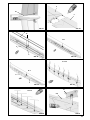
15. Preparing the wings
The first step here is to glue the wing panels 5 + 6 together in the
centre as shown. Ensure that they line up exactly. Any error at this
point will seriously affect the model’s flying characteristics.
Fig. 20
The following preparatory work is necessary before you install
the rectangular carbon fibre wing spars 9 + 10:
Lay out all the parts where you can reach them easily - the wing,
the spars, adhesive, a cloth - and clear away everything else
which could get in the way.
Since the spars are a very close fit in the wings, they displace
most of the adhesive when pressed into the recess; this causes
the glue to set very quickly. If you make a mistake at this point,
you may not be able to press the spars into position before the
glue sets.
Caution: the spars lie below the wing surface over part of
their length (dihedral). The exposed slots are covered later by
the stickers 16.
This procedure is crucial, and that is why we describe it very
carefully below. Please note that we will not replace spoiled
parts which result from using the wrong procedure!
a. Trial-fit the spars, i.e. press them into their slots ‘dry’ (without
glue).
b. Apply the adhesive (e.g. Elapor cyano) only to the bottom of the
spar slot in the wing.
c. Lay the wing down flat.
d. In one swift process, press the spar into the spar slot as far as
it will go.
e. Immediately wipe off excess glue where it is squeezed out of
the channel.
f. If necessary, flex the wing away from the spar slightly, across
the chord, and apply more glue.
Fig. 21
16. Additional wing reinforcements
The bottom spar cap 11.3 can now be glued to the underside of
the wing: lay the wing down flat with the curved tips extending
over the ends of the workbench before installing it. Fig. 22
Now turn the wing over and glue the top spar cap 11.4 in the spar
slot. It is a good idea to curve the spars beforehand where they
fit in the wingtip area. Fig. 23
Twenty diagonal braces 11.9 have to be glued to the top and
bottom of the wing in a ‘herringbone’ pattern; this is a special
measure designed to increase the torsional rigidity of the wing.
Please take great care over this procedure, and in particular
glue each brace to the top and bottom wing spars 11.4 + 11.3.
The diagonal braces are easier to install if you curve them to the
approximate shape beforehand.
Figs. 24 + 25
Completing the wing
17. Wing centre section doubler
Sand off the pimples on the central area of the wing where the
centre section doubler 15 fits, and glue the doubler in place
using cyano.
Fig. 26
18. Installing the aileron servos and the M6 socket
Temporarily place the servos in their recesses. Cut the servo
leads to the correct length and position them in the wing together
with the green M6 socket, as shown in Fig. 27.
Caution: check the wire assignment carefully; the insulation
colours on the plug and socket must match up correctly.
Back to the soldering iron!
Carefully separate the servo ribbon cable into its individual
colours using a pair of side-cutters. Strip a little insulation from
the wire ends, and tin (apply solder to) the bare conductors. Tin
the individual contacts of the M6 socket. Slip a piece of heat-
shrink sleeve over each wire, and solder the wire ends to the
contacts in the arrangement shown in Fig. 27.
Slip the sleeves over the soldered joints and shrink them in
place using a heat-gun or similar.
Press the servos into their wells, and secure them with a drop of
cyano at each mounting lug. Deploy the servo leads in the servo
lead ducts, pressing them into place with a blunt, flat instrument.
Place the connector in the holder and glue it in place as shown.
Ensure in particular that not the tiniest trace of adhesive gets
onto the surfaces which later come into contact with the
mating half of the connector, i.e. apply the glue to the socket
holder only.
19. Concealing the wing spars
Part of the main spar lies below the surface of the underside of
the wing; these channels can be covered by applying the stickers
16. The stickers improve the look of the model, and compensate
for the stepped height of the surface.
Fig. 28
20. Aileron linkages
Assemble the aileron horns from parts 24, 25 and 26, as shown
in Fig. 29, and carefully glue them in the appropriate recesses in

24
the ailerons. Connect the pre-formed aileron pushrods 28 to the
outermost hole in the servo output arms. At the other end slip the
wire pushrod 28 through the barrel 25 of the swivel connector.
Set the servos and the ailerons to centre, and tighten the
grubscrews 26 in the barrels to secure the pushrods.
Fig. 29
21. Concealing the aileron servos
Since the wings are extremely thin, the servos are installed flush
with the top surface of the airfoil. For aerodynamic reasons (and
to improve appearance) they should be covered using the thin,
rigid, self-adhesive stickers 26.
Fig. 30
22. Aileron pushrod fairings
The servo fairings 44 + 45 can now be fitted; they further improve
aerodynamic efficiency as well as protecting the aileron pushrods
(actually it is the servo gears which need protection).
Fig. 31
23. Fitting out the glider version
If you intend to fly your Blizzard at the slope, the simple option is
just to launch the model with the motor switched off; this provides
you with an emergency ‘get-you-home’ aid if the lift drops dead.
However, if you wish to make good use of weak lift, or if you are
simply a dedicated glider fan, the installation of a motor will be
unacceptable to you.
In this case attach the glider nose-cone 42 to the fuselage by
fitting the two screws 33 from the inside. The receiver battery
(e.g. # 16 6052) should be installed in the motor compartment.
The completed model will weigh about 200 g less than the
electric version.
24. Motor installation
Two power sets are available for the Blizzard: the standard
system, # 33 2639, offers an input power of 280 W, and is quite
powerful enough for a brisk style of flying. However, things really
start moving with the Tuning power system, # 33 2643, with an
input power of 470 W. In the latter case the pilot should certainly
have prior experience with fast ‘full-house’ models. The power
systems are installed as shown in Figs. 33 + 34.
Please note:
For the Tuning power system you must use the spacer ring 43.
If you wish to use a different motor, you should stay within the
power range 250 - 500 Watts. We strongly recommend that
you use the MPX spinner and driver as it looks good and
promotes efficient cooling.
Spinner and driver for 4 mm Ø shaft # 73 3501
Spinner and driver for 5 mm Ø shaft # 73 3502
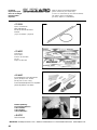
25. The canopy
Apply cyano to the canopy latch tongues 23 and push them into
the sockets in the canopy 12 as far as they will go. Fig. 35
26. Assembling the model
Connect the green M6 socket in the wing to the matching plug in
the fuselage, then fix the wing to the fuselage using the two
countersunk plastic screws 31. Check that everything fits and
lines up correctly. Fig. 36
27. Installing the receiving system components
The system components are installed as shown in Fig. 37. Note
that the receiver is positioned aft of the wing. This means that
the leads must be long enough to enable the servos to be
connected outside the fuselage.
28. Centre of Gravity
Set the correct Centre of Gravity by adjusting the position of the
flight battery and the trim ballast in the ballast chamber.
The correct CG position is around 70 mm aft of the wing root
leading edge. Fig. 38
29. Initial test-run
We assume that all the radio control system components are
installed as shown in Fig. 37, and connected correctly. Use Velcro
tape 20 + 21 to secure the components.
Check the neutral position of the control surfaces and the
direction of rotation of the servos. All the control systems must
operate freely, without binding. Check the direction of rotation of
the motor shaft, and reverse it if necessary.
30. Settings (guideline only!):
Centre of Gravity: 70 mm aft of the wing
root leading edge
Longitudinal dihedral: 1°
Motor downthrust: 6°
Motor sidethrust: 0°
Control surface travels:
Measured at the broadest chord of the control surfaces
Ailerons: 14 / 6 mm +/-
Elevator: 5 / 5 mm +/-
Rudder: 7 / 5 mm +/-
Flaps: 2 mm down
Spoilers: 12 mm up
Snap-flap: 2 mm up
Elevator compensation
Spoilers 0.5 mm ‘down’
Flap max. 1 mm ‘up’
Power 0.5 mm ‘down’
Expo, elevator: 30%
31. Test-flying:
Wait for a day with little or no wind.
Carry out all the basic adjustments in the peace and quiet of
your workshop!
The basic rules:
Snap-flaps negative and max. 2 mm
No speed flying with flaps deployed (i.e. neutral only)
Longitudinal dihedral = 1°; this is pre-set by the model’s
construction
Centre of Gravity:
Start by balancing the model within the stated range. Once you
have completed the test-flying schedule, you can fine-tune the
setting as follows: fly straight and level at half-throttle, and roll
the model inverted. If you now have to apply a great deal of ‘down’
to hold level flight, the model is nose-heavy; the CG must be
shifted further aft. If the machine climbs whilst inverted, without
requiring elevator correction, the CG is too far aft. When balanced
correctly, the model will require slight down-elevator for level
inverted flight.
Correcting straight and level flight:
First the static balance: hold the model inverted, and support it
by the spinner and the tail end of the fuselage: with the fuselage
level, the wings should remain horizontal. If not, add ballast to
the lighter wingtip.
On the next flight, fly the aeroplane at minimum throttle (just

25
enough power to keep the model in the air), keep it straight and
level, and adjust the trims for straight flight. Now switch to inverted
and check the straight flying characteristics. If necessary, adjust
the wingtip ballast after landing the model.
Sidethrust:
The sidethrust is built-in, and is suitable for all propellers around
the stated size.
Downthrust:
Apply full throttle, and fly the model straight and level until it comes
to the point where you are standing, so that you have a clear view
of the model from one side. Pull the aircraft up into a vertical
climb: it should continue to climb vertically, and not fall away
forward or back. If this is not the case, adjust the motor downthrust
to correct the fault.
An easy method of checking the approximate setting (adequate
when using the standard power system) is to trim the model for
a flat glide, then apply full-throttle: the aeroplane should now
climb away in a steady, shallow climb.
Aileron differential:
Fly three or four rolls to the right at half-throttle; if the Blizzard
veers to the right during this manoeuvre, you need to increase
the aileron differential. If it veers to the left, i.e. against the direction
of rolling, you should reduce the aileron differential.
32. Gilding the lily - applying the decals
The kit is supplied with a multi-colour decal sheet 2. Cut out the
individual name placards and emblems and apply them to the
model in the positions shown in the kit box illustration, or in an
arrangement which you find pleasing.
33. Safety
Safety is the First Commandment when flying any model aircraft.
Third party insurance should be considered a basic essential. If
you join a model club suitable cover will usually be available
through the organisation. It is your personal responsibility to
ensure that your insurance is adequate (powered model aircraft).
Make it your job to keep your models and your radio control
system in perfect order at all times. Check the correct charging
procedure for the batteries you are using. Make use of all sensi-
ble safety systems and precautions which are advised for your
system. An excellent source of practical accessories is the MUL-
TIPLEX main catalogue, as our products are designed and
manufactured exclusively by practising modellers for other
practising modellers.
Always fly with a responsible attitude. You may think that flying
low over other people’s heads is proof of your piloting skill; others
know better. The real expert does not need to prove himself in
such childish ways. Let other pilots know that this is what you
think too. Always fly in such a way that you do not endanger
yourself or others. Bear in mind that even the best RC system in
the world is subject to outside interference. No matter how many
years of accident-free flying you have under your belt, you have
no idea what will happen in the next minute.
All of us in the MULTIPLEX team hope you have many hours of
pleasure building and flying your new model.
MULTIPLEX Modellsport GmbH & Co. KG
Product development and maintenance
Klaus Michler

26
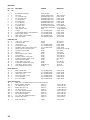
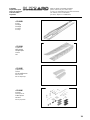
Blizzard KIT
Part No. Description Material Dimensions
No. off
1 1 KIT building instructions Paper, 80 g/m² A4
2 1 Decal set Printed adhesive film 330 x 700 mm
3 1 L.H. fuselage shell Moulded Elapor foam Ready made
4 1 R.H. fuselage shell Moulded Elapor foam Ready made
5 1 L.H. wing panel Moulded Elapor foam Ready made
6 1 R.H. wing panel Moulded Elapor foam Ready made
7 1 L.H. V-tail panel Moulded Elapor foam Ready made
8 1 R.H. V-tail panel Moulded Elapor foam Ready made
9 1 Front wing spar Rectangular CFRP tube 6 x 4 x 800 mm
10 1 Rear wing spar Rectangular CFRP tube 6 x 4 x 700 mm
11 1 GRP longeron (coil) GRP 1.3 Ø x 8500 mm
12 1 Canopy Inj. moulded plastic Ready made
13 1 Front fuselage fairing / motor bulkhead Inj. moulded plastic Ready made
14 2 Rear fuselage fairing Inj. moulded plastic Ready made
15 1 Wing centre section doubler Inj. moulded plastic Ready made
16 4 Spar cover sticker Self-adhesive plastic 13 x 400 mm
Small items set
20 3 Velcro tape, “mushroom” Plastic 25 x 60 mm
21 3 Velcro tape, “felt” Plastic 25 x 60 mm
22 2 Canopy latch Inj. moulded plastic Ready made
23 2 Canopy latch tongue Inj. moulded plastic Ready made
24 4 Glue-fitting ‘Twin’ control surface horn Inj. moulded plastic Ready made
25 4 Swivel pushrod connector barrel Metal Ready made, 6 mm Ø
26 4 Socket-head grubscrew Metal M3 x 3 mm
27 1 Allen key Metal 1.5 mm A/F
28 2 Aileron pushrod, one Z-bend Metal 1 Ø x 60 mm
29 2 V-tail pushrod Metal 1 Ø x 115 mm
30 2 Elevator pushrod, one Z-bend Metal 1 Ø x 145 mm
31 2 Countersunk wing retainer screw Plastic M5 x 20 mm
32 2 Nut (wing retainer plate) Metal M5
33 2 Screw (glider nose-cone) Metal M3 x 16 mm
34 1 Screw (trim compartment cover) Metal 2.2 x 6.5 mm
35 3 Trim ballast, electric version Steel ball, 9 g 13 mm Ø
36 2 Servo compartment cover, top Plastic 35 x 35 mm
Plastic parts set
40 1 Wing retainer plate Inj. moulded plastic Ready made
41 1 Trim ballast chamber cover Inj. moulded plastic Ready made
42 1 Glider nose-cone Inj. moulded plastic Ready made
43 1 Spacer ring, 39 Ø x 4 mm Inj. moulded plastic Ready made
44 1 L.H. servo fairing Inj. moulded plastic Ready made
45 1 R.H. servo fairing Inj. moulded plastic Ready made
Spars and longerons
11 1 Spar caps and fuselage longerons (roll, 1.3 Ø x 8500 mm)
11.1 2 Bottom tailplane spar cap GRP rod 1.3 Ø x 160 mm
11.2 2 Top tailplane spar cap GRP rod 1.3 Ø x 171 mm
11.3 1 Bottom wing spar cap GRP rod 1.3 Ø x 1345 mm
11.4 1 Top wing spar cap GRP rod 1.3 Ø x 1345 mm
11.5 2 L.H. / R.H. fuselage longeron GRP rod 1.3 Ø x 700 mm
11.6 1 Bottom fuselage longeron GRP rod 1.3 Ø x 723 mm
11.7 1 Top fuselage longeron GRP rod 1.3 Ø x 495 mm
11.8 2 L.H. / R.H. inner fuselage longeron GRP rod 1.3 Ø x 126 mm
11.9 20 Diagonal wing brace GRP rod 1.3 Ø x various
16 4 Spar cover sticker Plastic 13 x 400 mm

18
7
8
2
6
4
4
5
15
40
25
26
31
32
36
35
34
29
30
16
44
45
24
28
27
10
9
14
Abb. 1
Abb. 2
34
41
20
21
11
22
23
13
43
33
42

19
4
Abb. 03
Abb. 04
Abb. 05
Strecker M6 grün
# 8 5213
Abb. 06
Abb. 07
3
Abb. 08
Abb. 09
3
4
Abb. 10
3/4
13
4
4
3
4
14
11.5
22
40
11.8
~
-
+
~
-
+
32
32
40
14

20
5
11.2
26
Abb. 12
Abb. 13
8
Abb. 15
Abb. 11
Abb. 14
Abb. 17
Abb. 16
Abb. 18
7
8
3-4
3
7
11.1
11.1
8
4
41
35
34
14
11.7
30
30
25
24
8
11.6

21
Abb. 20
Abb. 21
Abb. 22
Abb. 23 Abb. 24
Abb. 25
Abb. 26
11.4
15
Abb. 19
6
5
9
5
6
10
29
5
6
6 x 11.9
4x 11.9
5+6
11.3
5

22
Abb. 27
Abb. 28
Abb. 29
Abb. 30
Abb. 31
Abb. 32
Abb. 34
Abb. 33
28
36
43
!
Antriebssatz / Powerset
16
42
45
-
+
+
-
Buchse M6 grün
# 8 5214
Antriebssatz / Powerset
TUNING # 33 2643
26
25
24
Oberseite
Top side
33
# 33 2639

23
Abb. 35
Abb. 36
Abb. 37
Abb. 38
Motor
31
70 mm
2.
1.
12
23
Abb. 39
12
Controler
Akku
Rx

39
# 22 4143
Rumpf
Fuselage
Fuselage
Fusoliera
Fuselaje
# 22 4144
Tragflächen
Wing panels
Aile principale
Semiali
Alas
# 22 4145
Leitwerkssatz
Tail set
Kit de stabilisateurs
Piani di coda
Kit de empenajes
# 22 4146
Kleinteile
Small parts set
Petites pièces
Minuteria
Piezas pequeñas
Ersatzteile (bitte bei Ihrem Fachhändler bestellen)
Replacement parts (please order from your model shop)
Pièces de rechanges (S.V.P. à ne commander que chez votre revendeur)
Parti di ricambio (da ordinare presso il rivenditore)
Repuestos (por favor, diríjase a su distribuidor)

40
MULTIPLEX Modellsport GmbH & Co.KG Westliche Gewerbestrasse 1 D-75015 Bretten-Gölshausen www.multiplex-rc.de
# 72 3131
Draht- und Holmsatz
Wire and spar set
Kit de clé d’aile et de renfort
RinforziI
Juego de alambres y largueros
# 72 4527
Dekorbogen
Decal sheet
Planche de décoration
Decals
Pliego de adhesivos
# 22 4147
Kunststoffteilesatz mit Kabinenhaube
pièces plastiques avec verrière
Plastic parts set incl. canopy
Parti in materiale plastico con capottina
piezas de plástico con cabina
Kleber Empfehlung!
Recommended adhesive!
Colle conseillée!
Colla cnsigliata!
cola recomendada !
# 59 2727
Zacki ELAPOR
Ersatzteile (bitte bei Ihrem Fachhändler bestellen)
Replacement parts (please order from your model shop)
Pièces de rechanges (S.V.P. à ne commander que chez votre revendeur)
Parti di ricambio (da ordinare presso il rivenditore)
Repuestos (por favor, diríjase a su distribuidor)
-
 1
1
-
 2
2
-
 3
3
-
 4
4
-
 5
5
-
 6
6
-
 7
7
-
 8
8
-
 9
9
-
 10
10
-
 11
11
-
 12
12
-
 13
13
-
 14
14
-
 15
15
-
 16
16


MULTIPLEX Blizzard Building Instructions
- Categoria
- Giocattoli telecomandati
- Tipo
- Building Instructions
- Questo manuale è adatto anche per
in altre lingue
- English: MULTIPLEX Blizzard
Documenti correlati
-
MULTIPLEX Blizzard Manuale del proprietario
-
-
HiTEC Parkmaster 3d Manuale del proprietario
-
-
-
MULTIPLEX Funcub Manuale del proprietario
-
-
-
MULTIPLEX FunJet Building Instructions
-
MULTIPLEX HERON 21 4276 Manuale del proprietario